JPZ0088Wireless Switch
Lutron Electronics Company Inc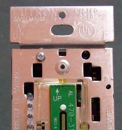
Click to zoom
Application Details
- Equipment Class
- DSR - Part 15 Remote Control/Security Device Transceiver
- Date of Grant
- Mar 01, 2012
- Application Purpose
- Original Equipment
- Date of Application
- Mar 01, 2012
- Equipment Note
- Wireless Switch
- Frequency Range
- 431.00000000 - 437.00000000
- Country
- United States
Documents & Files
Document Text
Text extracted from the exhibit documents filed with the FCC. Open a document above to read the original.
Users Manual
Wireless® Electronic Switch / Dimmer with Radio Frequency Receiver Installation instructions Please read before installing Interruptor Electrónico / Atenuador con Receptor de Radiofrecuencia Instrucciones de instalación Lea antes de instalar Interrupteur Électronique / Gradateur avec Récepteur Radiofréquence Directives d’installation Veuillez lire avant l’installation Interruptor Eletrônico / Dimmer com Receptor de Radiofrequência Instruções de instalação Leia antes de instalar Technical Assistance | Asistencia Técnica | Assistance Technique | Asistencia Técnica 1.800.523.9466 U.S.A., Canada, and the Caribbean +1.888.235.2910 México +1.610.282.3800 Others | Otros | Autres | Portuguese +1.610.282.1243 Fax | Télécopieur w w w . l u t r o n . c o m EnglishEspañolFrançais Derating Chart | Tabla de Reducción de la Potencia Nominal | Tableau de Déclassement | Diagrama de Redução de Carga * Note: The maximum lamp wattage is determined by the efficiency of the transformer, with 70%–85% as typical. * Nota: El total de vatios de las lámparas está determinado por la eficiencia del transformador, que típicamente es de 70%–85%. * Note: La puissance maximale des lampes est déterminée par l’efficacité du transformateur, soit typiquement 70–85%. * Nota: A potência máxima das lâmpadas é determinada pela taxa de eficiência do transformador, normalmente de 70 a 85%. K E Y Magnetic low-voltage* Bajo voltaje magnético* Magnétique à basse tension* Transformador eletromagnético de baixa voltagem* Electronic low-voltage Bajo voltaje electrónico Électronique à basse tension Transformador eletronico de baixa voltagem Incandescent Incandescente Incandescent Incandescente LED LED DEL LED Fluorescent Fluorescente Fluorescent Fluorescente General-purpose fan Ventilador para usos generales Ventilateur d’usage général Ventilador de uso geral Halogen Halógeno Halogène Halogênio ** In a triple-gang application, all MRF2-8S- DV gang units must be derated to 7A. ** Spanish: In a triple-gang application, all MRF2-8S- DV gang units must be derated to 7A. ** French: In a triple-gang application, all MRF2-8S- DV gang units must be derated to 7A. ** Portuguese: In a triple- gang application, all MRF2-8S-DV gang units must be derated to 7A. *** Total VA rating of transformer shall not exceed VA rating of switch. Transformer efficiency is typically 70%–80%. *** Spanish: Total VA rating of transformer shall not exceed VA rating of switch. Transformer efficiency is typically 70%–80%. *** French: Total VA rating of transformer shall not exceed VA rating of switch. Transformer efficiency is typically 70%–80%. *** Portuguese: Total VA rating of transformer shall not exceed VA rating of switch. Transformer efficiency is typically 70%–80%. Multigang | Múltiples Dispositivos | Jumelage Multiple | Instalações Múltiplas Model Modelo Modèle Modelo Load Type Tipo de Carga Type de Charge Tipo de Carga V~Hz Single Gang Dispositivo Único Simple Gang Simples End of Gang Fin de la Agrupación Fin de la Section à Jumelage Multiple Extremo Final do Gang Middle of Gang Mitad de la Agrupación Milieu de la Section à Jumelage Multiple Meio do Gang Este equipamento opera em caráter secundário, isto é, não tem direito à proteção contra interferência prejudicial, mesmo de estaçoes do mesmo tipo e não pode causar interferência a sistemas operando em caráter primário. SwitcheS | interruptoreS | interrupteurS | interruptor neutral | neutro | neutre | neutro MRF2-6ANS-DV 12050/60720W / VA600W / VA450W / VA 27750/601650W / VA1350W / VA1000W / VA 120–27750/606A5A3.5A 12050/601/10 HP (3A)1/10 HP (3A)1/10 HP (3A) MRF2-8ANS-120 12050/60950W / VA750W / VA600W / VA 12050/608A6.5A5A 12050/601/4 HP (5.8A)1/4 HP (5.8A)1/6 HP (4.4A) non-neutral | Spanish | French | portuguese MRF2-8S-DV 12050/60950W / VA (8A)950W / VA (8A)800W / VA (7A)** 27750/602000W / VA (7.5A)2000W / VA (7.5A)1900W / VA (7A)** 120–27750/608A8A7A** 12050/601/10 HP (3A)1/10 HP (3A)1/10 HP (3A) (01) 7898525200028 0839-11-6852 Modelo: MRF2-6MLV (01) 7898525200028 0839-11-6852 Modelo: MRF2-6MLV (01) 7898525200028 0839-11-6852 Modelo: MRF2-6MLV (01) 7898525200028 0839-11-6852 Modelo: MRF2-6MLV (01) 7898525200028 0839-11-6852 Modelo: MRF2-6MLV (01) 7898525200028 0839-11-6852 Modelo: MRF2-6MLV (01) 7898525200028 0839-11-6852 Modelo: MRF2-6MLV Model Modelo Modèle Modelo Load Type Tipo de Carga Type de Charge Tipo de Carga V~Hz Single Gang Dispositivo Único Simple Gang Simples End of Gang Fin de la Agrupación Fin de la Section à Jumelage Multiple Extremo Final do Gang Middle of Gang Mitad de la Agrupación Milieu de la Section à Jumelage Multiple Meio do Gang Este equipamento opera em caráter secundário, isto é, não tem direito à proteção contra interferência prejudicial, mesmo de estaçoes do mesmo tipo e não pode causar interferência a sistemas operando em caráter primário. DimmerS | SpaniSh | French | portugueSe neutral | neutro | neutre | neutro MRF2-6ND-12012050/60600W / VA500W / VA400W / VA MRF2-6ELV12050/60600W / VA500W / VA400W / VA MRF2-F6AN-DV120–27750/60 6A5A3.5A 60 Ballasts***50 Ballasts***35 Ballasts*** non-neutral | Spanish | French | portuguese MRF2-6MLV12050/60600W / VA500W / VA400W / VA MRF2-10D-12012050/601000W / VA800W / VA650W / VA MRF2-600M12050/60600W / VA500W / VA400W / VA 1 2 3 4 5 Réglage Tenir enfoncé le bouton de l’interrupteur électronique pour approximativement 6 secondes. Une fois que la DEL commence à briller faiblement, relâcher le bouton et aller à l’étape 2. Tenir enfoncé le bouton off du contrôleur sans fil ou du détecteur pour approximativement 6 secondes. Une fois que l’Interrupteur électronique apprend à reconnaître le contrôleur sans fil ou le détecteur, sa DEL et sa charge vont clignoter 3 fois et l’interrupteur quittera le mode réglage. Répéter les étapes 1—3 pour assigner de multiple contrôleurs sans fil ou capteurs à un interrupteur électronique. Répéter les étapes 1—3 pour assigner un contrôleur sans fil ou capteur à de multiple interrupteurs électroniques. Pour sauve …
Text truncated - open the document above for the full version.
Users Manual
FCC/ IC Information: This device complies with part 15 of the FCC Rules and Industry Canada license-exempt RSS standard(s). Operation is subject to the following two conditions: (1) This device may not cause interference, and (2) this device must accept any interference, including interference that may cause undesired operation. Modifications not expressly approved by Lutron Electronics Co., Inc. could void the user's authority to operate this equipment. Note: This equipment has been tested and found to comply with the limits for a Class B digital device, pursuant to part 15 of the FCC Rules. These limits are designed to provide reasonable protection against harmful interference in a residential installation. This equipment generates, uses and can radiate radio frequency energy and, if not installed and used in accordance with the instructions, may cause harmful interference to radio communications. However, there is no guarantee that interference will not occur in a particular installation. If this equipment does cause harmful interference to radio or television reception, which can be determined by turning the equipment off and on, the user is encouraged to try to correct the interference by one or more of the following measures: Reorient or relocate the receiving antenna Increase the separation between the equipment and receiver Connect the equipment into an outlet on a circuit different from that to which the receiver is connected Consult the dealer or an experienced radio/TV technician for help Información FCC/ IC: Este dispositivo cumple con las Reglas de la FCC, Parte 15 y con las normas RSS de Industry Canada para dispositivos exentos de licencia. La operación está sujeta a las dos condiciones siguientes: (1) Este dispositivo no debe causar interferencia perjudicial y (2) Este dispositivo debe aceptar cualquier interferencia recibida, incluyendo las que pueden causar una operación indeseada. Cualquier cambio o modificación sin la aprobación explícita de Lutron Electronics Co., Inc. pueden anular la autorización del usuario para operar el equipo. NOTA: Este equipo ha sido probado y se comprobó que cumple con los límites para un dispositivo digital de Clase B, de acuerdo con la Parte 15 de las Reglas de la FCC. Estos límites se han diseñado para proveer protección razonable contra interferencia dañina en una instalación residencial. Este equipo genera, usa y puede emitir energía de radio frecuencia y si no se instala y utiliza de acuerdo con las instrucciones, puede causar interferencia dañina a las comunicaciones de radio. Sin embargo, no hay garantía de que no ocurrirá interferencia en una instalación determinada. Si este equipo causa interferencia dañina a la recepción de la radio o la televisión, la cual se puede determinar encendiendo y apagando el equipo, el usuario puede tratar de corregir la interferencia mediante uno o más de los siguientes procedimientos: Volver a orientar o reubicar la antena receptora Aumentar la separación entre el equipo y el receptor Conectar el equipo a un tomacorriente que esté en un circuito diferente al del receptor Consultar al distribuidor o a un técnico experimentado en radio/TV Information de la FCC/ IC : http://www.lutron.com/Products/Components/PicoWirelessController/Documents/FCC.html Ce dispositif est conforme à la section 15 des règlements du FCC et des standards CNR exempt de licence d’Industrie Canada. L’opération est sous réserve des deux conditions suivantes : (1) Cet appareil ne peut causer d’interférence nuisible, et (2) Cet appareil doit tolérer toute interférence, même celle pouvant affecter son fonctionnement. Tout changement ou modification sans l’autorisation expresse de Lutron Electronics Co., Inc. pourrait annuler le droit d’utiliser cet équipement. REMARQUE : Cet équipement a été testé et jugé conforme aux limites applicables aux dispositifs numériques Classe B, conformément à la section 15 des règles de la FCC. Ces limites sont conçues pour procurer une protection raisonnable contre les perturbations nuisibles en application résidentielle. Cet équipement génère, utilise et peut radier l’énergie de fréquences radiophoniques. S’il n’est pas installé et utilisé selon les directives, peut causer des interférences radiophoniques nuisibles. Cependant, il n’y a aucune garantie à l’effet qu’aucune interférence ne se produira dans une installation précise. Si votre équipement produit de l’interférence à la réception radiophonique ou télévisuelle, ce qui peut être détecté en coupant et refermant l’alimentation au système d’éclairage. Dans le cas d’interférence, l’utilisateur sera contraint d’essayer de corriger la situation par un ou plusieurs des moyens suivants : Réorienter ou re-localiser l’antenne de réception Augmenter la distance séparant l’équipement et le récepteur Brancher l’équipement sur un circuit différent que celui sur lequel le récepteur est branché Demander l’aide du distributeur ou d’un technicien expérimenté en radio et télévision Informações da FCC/ IC: Este dispositivo está em conformidade com a Parte 15 das normas FCC e com as normas RSS de isenção de licença da indústria do Canadá. A operação está sujeita às duas condições abaixo: (1) Este dispositivo não deve causar interferência prejudicial e (2) este dispositivo aceita qualquer interferência recebida, incluindo interferência que possa causar funcionamento indesejado. Nota: Este equipamento foi testado e considerado adequado aos limites para a Classe B de dispositivos digitais, de acordo com a Parte 15 das normas da FCC. Esses limites foram criados para oferecer uma proteção razoável contra interferência nociva em uma instalação residencial. Este equipamento gera, usa e pode irradiar energia de radiofreqüência e, caso não seja instalado de acordo com as instruções, pode causar interferência nociva às comunicações de rádio. No entanto, não há garantia de que tal interferência não vá ocorrer em uma determinada instalação. Se esse equipamento causar interferênci…
Text truncated - open the document above for the full version.
External Photos
11CA63375 Photos
ID Label/Location Info
11CA63375 Photos 11CA63375 Photos
Internal Photos
11CA63375 Photos 11CA63375 Photos
Test Report
FCC CFR47 PART 15 SUBPART C INDUSTRY CANADA RSS-210 ISSUE 8 CERTIFICATION TEST REPORT FOR SWITCH MODEL NUMBER: RRD-6ANS-DV FCC ID: JPZ0088 IC: 2851A-JPZ0088 REPORT NUMBER: 1001451341 ISSUE DATE: 2012-01-13 REVISION DATE: 2012-02-29 Prepared for LUTRON ELECTRONICS INC 7200 SUTTER ROAD COOPERBURG PA 18036, USA Prepared by UL LLC 1285 WALT WHITMAN RD. MELVILLE, NY 11747, U.S.A. TEL: (631) 271-6200 FAX: (877) 854-3577 REPORT NO: 1001451341 DATE: 2012-01-13 REVISION DATE: 2012-02-29 FCC ID: JPZ0088 IC:2851A-JPZ0088 Page 2 of 57 UL LLC FORM NO: CCSUP4701D 1285 WALT WHITMAN RD, MELVILLE, NY 11747, USA TEL: (631) 271-6200 FAX: (877) 854-3577 This report shall not be reproduced except in full, without the written approval of UL LLC Revision History Rev. Issue Date Revisions Revised By -- 2012- 01-13 Initial Issue B. DeLisi -- 2012- 02-29 Updated text for Occupied Bandwidth tests and updated duty cycle correction factor and all affected emissions results with new DCF. B. DeLisi REPORT NO: 1001451341 DATE: 2012-01-13 REVISION DATE: 2012-02-29 FCC ID: JPZ0088 IC:2851A-JPZ0088 Page 3 of 57 UL LLC FORM NO: CCSUP4701D 1285 WALT WHITMAN RD, MELVILLE, NY 11747, USA TEL: (631) 271-6200 FAX: (877) 854-3577 This report shall not be reproduced except in full, without the written approval of UL LLC TABLE OF CONTENTS 1. ATTESTATION OF TEST RESULTS ................................................................................. 4 2. TEST METHODOLOGY ..................................................................................................... 5 3. FACILITIES AND ACCREDITATION ................................................................................. 5 4. CALIBRATION AND UNCERTAINTY ................................................................................ 5 4.1. MEASURING INSTRUMENT CALIBRATION .............................................................. 5 4.2. SAMPLE CALCULATION ............................................................................................ 5 4.3. MEASUREMENT UNCERTAINTY ............................................................................... 5 5. EQUIPMENT UNDER TEST ............................................................................................... 6 5.1. DESCRIPTION OF EUT .............................................................................................. 6 5.2. DESCRIPTION OF AVAILABLE ANTENNAS .............................................................. 6 5.3. SOFTWARE AND FIRMWARE .................................................................................... 6 5.4. CONFIGURATION AND MODE ................................................................................... 6 5.5. MODIFICATIONS ........................................................................................................ 6 5.6. DESCRIPTION OF TEST SETUP ................................................................................ 7 6. TEST AND MEASUREMENT EQUIPMENT ....................................................................... 9 7. ANTENNA PORT TEST RESULTS ...................................................................................11 7.1. 20 dB AND 99% BW ...................................................................................................11 7.2. DUTY CYCLE .............................................................................................................15 7.3. TRANSMISSION TIME ...............................................................................................18 8. RADIATED EMISSION TEST RESULTS...........................................................................19 8.1. TX RADIATED SPURIOUS EMISSION ......................................................................19 8.2. RX RADIATED SPURIOUS EMISSION ......................................................................30 9. AC MAINS LINE CONDUCTED EMISSIONS ....................................................................39 10. SETUP PHOTOS ...........................................................................................................52 REPORT NO: 1001451341 DATE: 2012-01-13 REVISION DATE: 2012-02-29 FCC ID: JPZ0088 IC:2851A-JPZ0088 Page 4 of 57 UL LLC FORM NO: CCSUP4701D 1285 WALT WHITMAN RD, MELVILLE, NY 11747, USA TEL: (631) 271-6200 FAX: (877) 854-3577 This report shall not be reproduced except in full, without the written approval of UL LLC 1. ATTESTATION OF TEST RESULTS COMPANY NAME: LUTRON ELECTRONICS INC 7200 SUTTER ROAD COOPERBURG, PA 18036, USA EUT DESCRIPTION: Switch MODEL: RRD-6ANS-DV SERIAL NUMBER: Non-serialized production unit DATE TESTED: 2012-01-06 through 2012-02-29 APPLICABLE STANDARDS STANDARD TEST RESULTS FCC PART 15 SUBPART C Pass INDUSTRY CANADA RSS-210 Issue 8, Annex 1 Pass INDUSTRY CANADA RSS-GEN Issue 3 Pass UL LLC tested the above equipment in accordance with the requirements set forth in the above standards, using test results reported in the test report documents referenced below and/or documentation furnished by the applicant. All indications of Pass/Fail in this report are opinions expressed by UL LLC based on interpretations of these calculations. The results show that the equipment is capable of demonstrating compliance with the requirements as documented in this report. Note: The results documented in this report apply only to the tested sample, under the conditions and modes of operation, as described by the referenced documents. This document may not be altered or revised in any way unless done so by UL LLC and all revisions are duly noted in the revisions section. Any alteration of this document not carried out by UL LLC will constitute fraud and shall nullify the document. This report must not be used by the client to claim product certification, approval, or endorsement by NVLAP, NIST, any agency of the Federal Government, or any agency of any government. Approved & Released For UL By: Tested By: Joseph Danisi Bob DeLisi Lead Engineering Assoicate Sr. Staff Engineer UL L…
Text truncated - open the document above for the full version.
Test Setup Photos
1. SETUP PHOTOS ANTENNA PORT ANTENNA PORT RADIATED EMISSION ABOVE 30 MHz RADIATED EMISSIONS ABOVE 30 MHz (FRONT) RADIATED EMISSIONS ABOVE 30 MHz (BACK) AC MAINS LINE CONDUCTED EMISSION LINE CONDUCTED EMISSION (FRONT) END OF REPORT LINE CONDUCTED EMISSION (BACK)
Contact Information
Applicant
Daniel Schlegel(Standards Compliance Supervisor)
Test Firm
UL LLCBob Delisi
Technical Specifications
| # | Rule Parts | Frequency Range | Power Output |
|---|---|---|---|
| 1 | 15.231 | 431 MHz - 437 MHz | - |
Other Applications from Lutron Electronics Company Inc
JPZ0161
Sep 03, 2026Wireless Interface
Equipment Class
DTS - Digital Transmission SystemJPZ0159
Aug 12, 2026Wireless Processor
Equipment Class
DTS - Digital Transmission SystemJPZ0158
Jul 27, 2026Copy of Wireless Processor
Equipment Class
DTS - Digital Transmission SystemJPZ0157
Mar 26, 2026LED Downlight
Equipment Class
DTS - Digital Transmission SystemJPZ0155
Sep 30, 2024LED Lighting Controller
Equipment Class
DTS - Digital Transmission System