JPZ0096Relay Module
Lutron Electronics Company Inc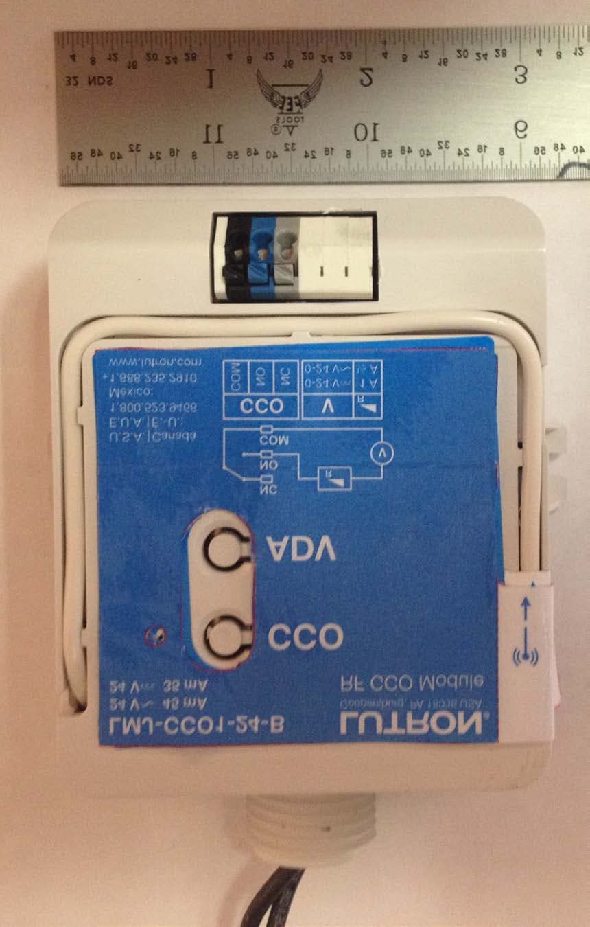
Click to zoom
Application Details
- Equipment Class
- DSR - Part 15 Remote Control/Security Device Transceiver
- Date of Grant
- Sep 30, 2013
- Application Purpose
- Original Equipment
- Date of Application
- Sep 30, 2013
- Equipment Note
- Relay Module
- Frequency Range
- 431.00000000 - 437.00000000
- Country
- United States
Documents & Files
Document Text
Text extracted from the exhibit documents filed with the FCC. Open a document above to read the original.
Users Manual
Lutron Electronics Co., Inc. | 7200 Suter Road Coopersburg, PA 18036-1299, U.S.A. RF CCO Module | Installation 041424 Rev. A 05/2013 Important Notes: Please read before installing. • For installation by a qualified electrician in accordance with all local and national electrical codes. • Note: Use copper conductors only. • Check to see that the device type and rating is suitable for the application. • DO NOT install if product has any visible damage. • If moisture or condensation is evident, allow the product to dry completely before installation. • Operate between 32 °F to 131 °F (0 °C to 55 °C). • 0% to 90% humidity, non-condensing. • For indoor use only. • 24 V~ or 24 V- supply and load shall be protected via an approved power source in accordance with IEC/ EN61558-2 (SELV supply). LMJ-CCO1-24-B 24 V~ 45 mA 24 V- 35 mA FCC Information: (LMJ- model only) This device complies with part 15 of the FCC Rules and Industry Canada licence-exempt RSS standard(s). Operation is subject to the following two conditions: (1) This device may not cause interference, and (2) this device must accept any interference, including interference that may cause undesired operation. Modifications not expressly approved by Lutron Electronics Co., Inc. could void the user’s authority to operate this equipment. NOTE: This equipment has been tested and found to comply with the limits for a Class B digital device, pursuant to part 15 of the FCC Rules. These limits are designed to provide reasonable protection against harmful interference in a residential installation. This equipment generates, uses and can radiate radio frequency energy and, if not installed and used in accordance with the instructions, may cause harmful interference to radio communications. However, there is no guarantee that interference will not occur in a particular installation. If this equipment does cause harmful interference to radio or television reception, which can be determined by turning the equipment off and on, the user is encouraged to try to correct the interference by one or more of the following measures: • Reorient or relocate the receiving antenna. • Increase the separation between the equipment and receiver. • Connect the equipment into an outlet on a circuit different from that to which the receiver is connected. Warranty: For warranty information, please visit www.lutron.com/TechnicalDocumentLibrary/Warranty.pdf www.lutron.com/TechnicalDocumentLibrary/Intl_Warranty.pdf Lutron and are registered trademarks of Lutron Electronics Co., Inc. ©2013 Lutron Electronics Co., Inc. CCO Status LED CCO Toggle Advanced Operations For System Setup Guide and tools visit www.lutron.com RF CCO Module RF CCO Module Operation Reset Factory Defaults Note: In some instances it may be necessary to reset the RF CCO Module back to factory default settings. A Triple-tap the Advanced Operations (“ADV”) button, on the RF CCO Module and hold until the LED begins to flash slowly. Within 3 seconds of flashing, release and triple-tap the button again and the LED will flash rapidly indicating that the unit has been reset to factory defaults. B Note: Any associations or programming previously set up with the unit will be lost and will need to be re-programmed. CCO- controlled device does not respond to Wireless Transmitter(s). • Ensure power to the RF CCO Module is properly applied. • Ensure the CCO- controlled device has been properly wired to the RF CCO Module. • Ensure RF CCO module has been activated in the system. • Ensure that the Wireless Transmitter battery is installed correctly. RF CCO Module does not respond to a keypad, wireless controller or sensor. • Improper programming. Program from system programming software. • Out of RF Range. Reposition to be within 30 ft (9 m) of an RF signal repeater. • Already at current level. The RF CCO Module has already responded to a command, or is already at the requested setting. • Wireless controller or sensor batteries low or installed incorrectly. Replace or install batteries properly. • RF interference. Do not run RF CCO Module wires with other power wires or communication wires (e.g., networking, audio, or video signals). Troubleshooting English When installing a RF CCO Module, wire the module as shown. Note: RF CCO Module may also be mounted on or inside a junction box. If installing unit inside a junction box please see Application Note #423. For more information: www.lutron.com Installation: LMJ-, LMM-, LMQ- models The RF CCO Module should be installed using the mounting tabs on the enclosure (screws not provided). The RF CCO Module can be installed in a junction box or marshalling box (optional) using the conduit nut (provided) or with mounting screws (not provided). Please consult local and national electric codes for proper installation. RF CCO Module Placement RF CCO Modules must be located within 30 ft (9 m) of an RF signal repeater. RF CCO modules cannot be controlled by the system until they are programmed using the system programming software. Shock Hazard. May result in serious injury or death. Turn off power at circuit breaker before installing the unit. WARNING Installation: LMK- and LMN- models NECR Class 2 LMK-CCO1-24-B LMN-CCO1-24-B LMM-CCO1-24-B LMQ-CCO1-24-B 24 V~ 45 mA 24 V- 35 mA SELV Contact Closure Output (CCO) 24 V~ or 24 V- NO (Normally Open) NC (Normally Closed) COM (Common) Note: When wiring CCO output, use 20 AWG to 16 AWG (0.5 mm 2 to 1.5 mm 2 ) solid or stranded wire. To CCO-controlled device. Note: CCO Module supply wires can be connected in any polarity. Mounting screw (2 Supplied) Wire Nut (2 Supplied) 24 V~ or 24 V- NO (Normally Open) NC (Normally Closed) COM (Common) Note: When wiring CCO output, use 0.5 mm 2 to 1.5 mm 2 (20 AWG to 16 AWG) solid or stranded wire. To CCO-controlled device. Note: CCO Module supply wires can be connected in any polarity. Conduit Nut 21 mm knockout opening For LMN-CCO-24-B use supplied Twist-on wire connectors. (2 supplied) 1 2 3 10 mm Wiring …
Text truncated - open the document above for the full version.
Users Manual
Lutron Electronics Co., Inc. | 7200 Suter Road Coopersburg, PA 18036-1299, U.S.A. RF Relay Module | Installation with SoftswitchR 041423 Rev. A 08/2013 Important Notes: • For installation by a qualified electrician in accordance with all local and national electrical codes. • Note: Use copper conductors only. • Check to see that the device type and rating is suitable for the application. • DO NOT install if product has any visible damage. • If moisture or condensation is evident, allow the product to dry completely before installation. • Operate between 32 °F to 131 °F (0 °C to 55 °C). • 0% to 90% humidity, non-condensing. • For indoor use only. Please read before installing LMJ-16R-DV-B 120 / 277 V~ 50 / 60 Hz 16 A 1/2 HP at 120 V~ 1 1 ⁄2 HP at 277 V~ UL 2043 Plenum Rated LMK-16R-DV-B LMN-16R-DV-B LMM-16R-DV-B LMQ-16R-DV-B 220 - 240 V~ 50 / 60 Hz 16 A 6 A Motor (LMK- Model) FCC Information: (LMJ- model only) This device complies with part 15 of the FCC Rules and Industry Canada license-exempt RSS standard(s). Operation is subject to the following two conditions: (1) This device may not cause interference, and (2) this device must accept any interference, including interference that may cause undesired operation. Modifications not expressly approved by Lutron Electronics Co., Inc. could void the user’s authority to operate this equipment. NOTE: This equipment has been tested and found to comply with the limits for a Class B digital device, pursuant to part 15 of the FCC Rules. These limits are designed to provide reasonable protection against harmful interference in a residential installation. This equipment generates, uses and can radiate radio frequency energy and, if not installed and used in accordance with the instructions, may cause harmful interference to radio communications. However, there is no guarantee that interference will not occur in a particular installation. If this equipment does cause harmful interference to radio or television reception, which can be determined by turning the equipment off and on, the user is encouraged to try to correct the interference by one or more of the following measures: • Re-orient or relocate the receiving antenna. • Increase the separation between the equipment and receiver. • Connect the equipment into an outlet on a circuit different from that to which the receiver is connected. Warranty: For warranty information, please visit www.lutron.com/TechnicalDocumentLibrary/Warranty.pdf www.lutron.com/TechnicalDocumentLibrary/Intl_Warranty.pdf Lutron and are registered trademarks of Lutron Electronics Co., Inc. ©2013 Lutron Electronics Co., Inc. Load Status LED Relay Toggle Advanced Operations For System Setup Guide and tools visit www.lutron.com RF Relay Module RF Relay Module Operation Reset Factory Defaults Note: In some instances it may be necessary to reset the RF Relay Module back to factory default settings. A Triple-tap the Advanced Operations (“ADV”) button, on the RF Relay Module and hold until the LED begins to flash slowly. Within 3 seconds of flashing, release and triple-tap the button again and the LED will flash rapidly indicating that the unit has been reset to factory defaults. B Note: Any associations or programming previously set up with the unit will be lost and will need to be re-programmed. Troubleshooting English When installing a RF Relay Module, use the supplied conduit nut and wire the module as shown. If installing unit inside a junction box, please see Application Note #423. For more information: www.lutron.com Installation: LMJ-, LMQ-, and LMM- models Conduit Nut White (Neutral) Black (Hot) Red (Switched Hot) To Load Technical Assistance | 1.800.523.9466 USA, Canada, and the Caribbean | +44.(0)20.7702.0657 Europe | +1.610.282.3800 Others | www.lutron.com RF Relay Module can be installed in a junction box or marshalling box (optional) using the conduit nut (provided) or with mounting screws (not provided). Please consult local and national electric codes for proper installation. RF Relay Module Placement RF Relay Modules must be located within 30 ft (9 m) of an RF signal repeater. RF relay modules cannot be controlled by the system until they are programmed using the system programming software. Shock Hazard. May result in serious injury or death. Turn off power at circuit breaker before installing the unit. WARNING Installation: LMK- and LMN- models Blue (LMK-), Black (LMN-) (Neutral) Brown (LMK-), Red (LMN-) (Line) Black (LMK-), Yellow (LMN-) (Switched Line) Conduit Nut 21 mm knockout opening To Load For LMN-16R-DV-B use supplied Twist-on wire connectors. (3 supplied) 1 2 3 10 mm Wiring a Lever Operated Connector (shown) When wiring lever operated connectors (3 supplied) please use 14 AWG to 12 AWG (2.5 mm 2 to 4.0 mm 2 ) diameter solid or stranded copper wire. 220 - 240 V~ 50/60 Hz Load does not respond to Wireless Transmitter(s). • Ensure breaker to the RF Relay Module is on. • Ensure the load has been properly wired to the RF Relay Module. • Ensure that the RF Relay Module has been activated in the system. • Ensure that the Wireless Transmitter battery is installed correctly. RF Relay Module does not respond to a keypad, wireless controller or sensor. • Improper programming. Program from the system programming software. • Out of RF Range. Reposition to be within 30 ft (9 m) of an RF signal repeater. • Already at current level. The RF Relay Module has already responded to a command, or is already at the requested setting. • Wireless controller or sensor batteries low or installed incorrectly. Replace or install batteries properly. • RF interference. Do not run RF Relay Module wires with other power wires or communication wires (e.g., networking, audio, or video signals). 120/277 V~ 50/60 Hz (LMJ- model) 220 - 240 V~ 50/60 Hz (LMQ- and LMM- models)
External Photos
Front Label LMJ-16R-DV-B represents models number LMJ-16RCCO1-DV-B, LMJ-5R-DV-B and LMJ- 5RCCO1-DV-B front labels,
Internal Photos
LMJ-16RCCO1-DV-B internal photos shown which is identical in construction to and LMJ-5RCCO1-DV-B. Device represents models numb.er LMJ-16R-DV-B and LMJ-5R-DV-B which have identical construction without CCO1 relay populated
Test Report
FCC CFR47 PART 15 SUBPART C INDUSTRY CANADA RSS-210 ISSUE 8 CERTIFICATION TEST REPORT FOR CCO MODULE MODEL NUMBER: LMJ-16RCC01-DV-B FCC ID: JPZ0096 IC: 2851A- JPZ0096 REPORT NUMBER: 10012459 ISSUE DATE:2013-09-10 Prepared for LUTRON ELECTRONICS CO INC 7200 SUTER RD COOPERSBURG , PA 18036 USA Prepared by UL LLC 1285 WALT WHITMAN RD. MELVILLE, NY 11747, U.S.A. TEL: (631) 271-6200 FAX: (877) 854-3577 REPORT NO: 10012459 DATE: 2013-09-10 FCC ID: JPZ0096 IC: 2851A- JPZ0096 Page 2 of 60 UL LLC. FORM NO: CCSUP4701D 1285 WALT WHITMAN RD, MELVILLE, NY 11747, USA TEL: (631) 271-6200 FAX: (877) 854-3577 This report shall not be reproduced except in full, without the written approval of UL LLC. Revision History Rev. Issue Date Revisions Revised By -- 2013- 09-10 Initial Issue B. DeLisi REPORT NO: 10012459 DATE: 2013-09-10 FCC ID: JPZ0096 IC: 2851A- JPZ0096 Page 3 of 60 UL LLC. FORM NO: CCSUP4701D 1285 WALT WHITMAN RD, MELVILLE, NY 11747, USA TEL: (631) 271-6200 FAX: (877) 854-3577 This report shall not be reproduced except in full, without the written approval of UL LLC. TABLE OF CONTENTS 1. ATTESTATION OF TEST RESULTS ................................................................................. 4 2. TEST METHODOLOGY ..................................................................................................... 5 3. FACILITIES AND ACCREDITATION ................................................................................. 5 4. CALIBRATION AND UNCERTAINTY ................................................................................ 5 4.1. MEASURING INSTRUMENT CALIBRATION .............................................................. 5 4.2. SAMPLE CALCULATION ............................................................................................ 5 4.3. MEASUREMENT UNCERTAINTY ............................................................................... 5 5. EQUIPMENT UNDER TEST ............................................................................................... 6 5.1. DESCRIPTION OF EUT .............................................................................................. 6 5.2. DESCRIPTION OF AVAILABLE ANTENNAS .............................................................. 6 5.3. SOFTWARE AND FIRMWARE .................................................................................... 6 5.4. WORST-CASE CONFIGURATION AND MODE .......................................................... 6 5.5. MODIFICATIONS ........................................................................................................ 6 5.6. DESCRIPTION OF TEST SETUP ................................................................................ 7 6. TEST AND MEASUREMENT EQUIPMENT ....................................................................... 9 7. ANTENNA PORT TEST RESULTS ...................................................................................11 7.1. 20 dB AND 99% BW ...................................................................................................11 7.2. DUTY CYCLE .............................................................................................................15 7.3. TRANSMISSION TIME ...............................................................................................19 8. RADIATED EMISSION TEST RESULTS...........................................................................21 8.1. TX RADIATED SPURIOUS EMISSION ......................................................................21 8.2. RX RADIATED SPURIOUS EMISSION ......................................................................34 9. AC MAINS LINE CONDUCTED EMISSIONS ....................................................................39 10. SETUP PHOTOS ...........................................................................................................52 REPORT NO: 10012459 DATE: 2013-09-10 FCC ID: JPZ0096 IC: 2851A- JPZ0096 Page 4 of 60 UL LLC. FORM NO: CCSUP4701D 1285 WALT WHITMAN RD, MELVILLE, NY 11747, USA TEL: (631) 271-6200 FAX: (877) 854-3577 This report shall not be reproduced except in full, without the written approval of UL LLC. 1. ATTESTATION OF TEST RESULTS COMPANY NAME: Lutron Electronics Co Inc 7200 Suter Rd Coopersburg, PA 18036 USA EUT DESCRIPTION: CCO Module MODEL: LMJ-16RCC01-DV-B SERIAL NUMBER: Non-serialized production unit DATE TESTED: 2013-06-03 through 2013-08-26 APPLICABLE STANDARDS STANDARD TEST RESULTS FCC PART 15 SUBPART C Pass INDUSTRY CANADA RSS-210 Issue 8, Annex 1 Pass INDUSTRY CANADA RSS-GEN Issue 3 Pass UL LLC tested the above equipment in accordance with the requirements set forth in the above standards, using test results reported in the test report documents referenced below and/or documentation furnished by the applicant. All indications of Pass/Fail in this report are opinions expressed by UL LLC based on interpretations of these calculations. The results show that the equipment is capable of demonstrating compliance with the requirements as documented in this report. Note: The results documented in this report apply only to the tested sample, under the conditions and modes of operation, as described by the referenced documents. This document may not be altered or revised in any way unless done so by UL LLC and all revisions are duly noted in the revisions section. Any alteration of this document not carried out by UL LLC will constitute fraud and shall nullify the document. This report must not be used by the client to claim product certification, approval, or endorsement by NVLAP, NIST, any agency of the Federal Government, or any agency of any government. Approved & Released For UL By: Tested By: Mike Antola Bob DeLisi WiSE Project Lead WiSE Principal Engineer UL UL REPORT NO: 10012459 DATE: 2013-09-10 FCC ID: JPZ0096 IC: 2851A- JPZ0096 Page 5 of 60 UL LLC. FORM NO: CCSUP4701D 1285 WALT WHITMAN RD, MELVILLE, NY 11747, USA TEL: (631) 271-6200 FAX: (877) 854-3577 This report shall not be reproduced except in full, with…
Text truncated - open the document above for the full version.
Test Report
FCC CFR47 PART 15 SUBPART C INDUSTRY CANADA RSS-210 ISSUE 8 CERTIFICATION TEST REPORT FOR CCO MODULE MODEL NUMBER: LMJ-CC01-24-B FCC ID: JPZ0096 IC: 2851A-JPZ0096 REPORT NUMBER: 10012459 ISSUE DATE: 2013-09-10 Prepared for LUTRON ELECTRONICS CO INC 7200 SUTER RD COOPERSBURG , PA 18036 USA Prepared by UL LLC 1285 WALT WHITMAN RD. MELVILLE, NY 11747, U.S.A. TEL: (631) 271-6200 FAX: (877) 854-3577 REPORT NO: 10012459 DATE: 2013-09-10 FCC ID: JPZ0096 IC: 2851A-JPZ0096 Page 2 of 45 UL LLC. FORM NO: CCSUP4701D 1285 WALT WHITMAN RD, MELVILLE, NY 11747, USA TEL: (631) 271-6200 FAX: (877) 854-3577 This report shall not be reproduced except in full, without the written approval of UL LLC. Revision History Rev. Issue Date Revisions Revised By -- 2013- 09-10 Initial Issue B. DeLisi REPORT NO: 10012459 DATE: 2013-09-10 FCC ID: JPZ0096 IC: 2851A-JPZ0096 Page 3 of 45 UL LLC. FORM NO: CCSUP4701D 1285 WALT WHITMAN RD, MELVILLE, NY 11747, USA TEL: (631) 271-6200 FAX: (877) 854-3577 This report shall not be reproduced except in full, without the written approval of UL LLC. TABLE OF CONTENTS 1. ATTESTATION OF TEST RESULTS ................................................................................. 4 2. TEST METHODOLOGY ..................................................................................................... 5 3. FACILITIES AND ACCREDITATION ................................................................................. 5 4. CALIBRATION AND UNCERTAINTY ................................................................................ 5 4.1. MEASURING INSTRUMENT CALIBRATION .............................................................. 5 4.2. SAMPLE CALCULATION ............................................................................................ 5 4.3. MEASUREMENT UNCERTAINTY ............................................................................... 5 5. EQUIPMENT UNDER TEST ............................................................................................... 6 5.1. DESCRIPTION OF EUT .............................................................................................. 6 5.2. DESCRIPTION OF AVAILABLE ANTENNAS .............................................................. 6 5.3. SOFTWARE AND FIRMWARE .................................................................................... 6 5.4. WORST-CASE CONFIGURATION AND MODE .......................................................... 6 5.5. MODIFICATIONS ........................................................................................................ 6 5.6. DESCRIPTION OF TEST SETUP ................................................................................ 7 6. TEST AND MEASUREMENT EQUIPMENT ....................................................................... 9 7. ANTENNA PORT TEST RESULTS ...................................................................................11 7.1. 20 dB AND 99% BW ...................................................................................................11 7.2. DUTY CYCLE .............................................................................................................15 7.3. TRANSMISSION TIME ...............................................................................................19 8. RADIATED EMISSION TEST RESULTS...........................................................................21 8.1. TX RADIATED SPURIOUS EMISSION ......................................................................21 8.2. RX RADIATED SPURIOUS EMISSION ......................................................................34 9. SETUP PHOTOS ...............................................................................................................39 REPORT NO: 10012459 DATE: 2013-09-10 FCC ID: JPZ0096 IC: 2851A-JPZ0096 Page 4 of 45 UL LLC. FORM NO: CCSUP4701D 1285 WALT WHITMAN RD, MELVILLE, NY 11747, USA TEL: (631) 271-6200 FAX: (877) 854-3577 This report shall not be reproduced except in full, without the written approval of UL LLC. 1. ATTESTATION OF TEST RESULTS COMPANY NAME: Lutron Electronics Co Inc 7200 Suter Rd Coopersburg, PA 18036 USA EUT DESCRIPTION: CCO Module MODEL: LMJ-CC01-24-B SERIAL NUMBER: Non-serialized production unit DATE TESTED: 2013-06-03 through 2013-08-26 APPLICABLE STANDARDS STANDARD TEST RESULTS FCC PART 15 SUBPART C Pass INDUSTRY CANADA RSS-210 Issue 8, Annex 1 Pass INDUSTRY CANADA RSS-GEN Issue 3 Pass UL LLC tested the above equipment in accordance with the requirements set forth in the above standards, using test results reported in the test report documents referenced below and/or documentation furnished by the applicant. All indications of Pass/Fail in this report are opinions expressed by UL LLC based on interpretations of these calculations. The results show that the equipment is capable of demonstrating compliance with the requirements as documented in this report. Note: The results documented in this report apply only to the tested sample, under the conditions and modes of operation, as described by the referenced documents. This document may not be altered or revised in any way unless done so by UL LLC and all revisions are duly noted in the revisions section. Any alteration of this document not carried out by UL LLC will constitute fraud and shall nullify the document. This report must not be used by the client to claim product certification, approval, or endorsement by NVLAP, NIST, any agency of the Federal Government, or any agency of any government. Approved & Released For UL By: Tested By: Mike Antola Bob DeLisi WiSE Project Lead WiSE Principal Engineer UL UL REPORT NO: 10012459 DATE: 2013-09-10 FCC ID: JPZ0096 IC: 2851A-JPZ0096 Page 5 of 45 UL LLC. FORM NO: CCSUP4701D 1285 WALT WHITMAN RD, MELVILLE, NY 11747, USA TEL: (631) 271-6200 FAX: (877) 854-3577 This report shall not be reproduced except in full, without the written approval of UL LLC. 2. TEST METHODOLOGY The tests documented in this report were performed in accor…
Text truncated - open the document above for the full version.
Test Setup Photos
1. SETUP PHOTOS ANTENNA PORT ANTENNA PORT RADIATED EMISSION FOR PORTABLE CONFIGURATION – X ORIENTATION RADIATED EMISSION FOR PORTABLE CONFIGURATION – X ORIENTATION RADIATED EMISSION FOR PORTABLE CONFIGURATION – Y ORIENTATION RADIATED EMISSION FOR PORTABLE CONFIGURATION – Y ORIENTATION RADIATED EMISSION FOR PORTABLE CONFIGURATION – Z ORIENTATION RADIATED EMISSION FOR PORTABLE CONFIGURATION – Z ORIENTATION RADIATED EMISSION BELOW 30 MHz RADIATED EMISSIONS BELOW 30 MHz (FRONT) RADIATED EMISSIONS BELOW 30 MHz (REAR) RADIATED EMISSION ABOVE 30 MHz RADIATED EMISSIONS ABOVE 30 MHz (FRONT) RADIATED EMISSIONS ABOVE 30 MHz (BACK) AC MAINS LINE CONDUCTED EMISSION LINE CONDUCTED EMISSION (FRONT) END OF REPORT LINE CONDUCTED EMISSION (BACK)
Test Setup Photos
1. SETUP PHOTOS ANTENNA PORT ANTENNA PORT RADIATED EMISSION FOR PORTABLE CONFIGURATION – X ORIENTATION RADIATED EMISSION FOR PORTABLE CONFIGURATION – X ORIENTATION RADIATED EMISSION FOR PORTABLE CONFIGURATION – Y ORIENTATION RADIATED EMISSION FOR PORTABLE CONFIGURATION – Y ORIENTATION RADIATED EMISSION FOR PORTABLE CONFIGURATION – Z ORIENTATION RADIATED EMISSION FOR PORTABLE CONFIGURATION – Z ORIENTATION RADIATED EMISSION BELOW 30 MHz RADIATED EMISSIONS BELOW 30 MHz (FRONT) RADIATED EMISSIONS BELOW 30 MHz (REAR) RADIATED EMISSION ABOVE 30 MHz RADIATED EMISSIONS ABOVE 30 MHz (FRONT) END OF REPORT RADIATED EMISSIONS ABOVE 30 MHz (BACK)
Contact Information
Applicant
Daniel Schlegel(Standards Compliance Supervisor)
Test Firm
UL LLCRick Titus
Technical Specifications
| # | Rule Parts | Frequency Range | Power Output |
|---|---|---|---|
| 1 | 15.231 | 431 MHz - 437 MHz | - |
Other Applications from Lutron Electronics Company Inc
JPZ0161
Sep 03, 2026Wireless Interface
Equipment Class
DTS - Digital Transmission SystemJPZ0159
Aug 12, 2026Wireless Processor
Equipment Class
DTS - Digital Transmission SystemJPZ0158
Jul 27, 2026Copy of Wireless Processor
Equipment Class
DTS - Digital Transmission SystemJPZ0157
Mar 26, 2026LED Downlight
Equipment Class
DTS - Digital Transmission SystemJPZ0155
Sep 30, 2024LED Lighting Controller
Equipment Class
DTS - Digital Transmission System