JPZ0110Wireless In-Wall Dimmer Switch
Lutron Electronics Company Inc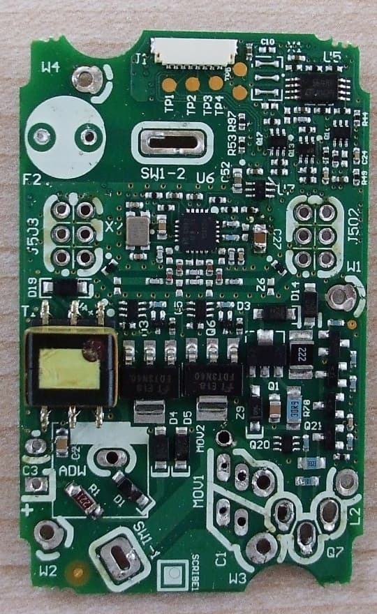
Click to zoom
Application Details
- Equipment Class
- DSR - Part 15 Remote Control/Security Device Transceiver
- Date of Grant
- Feb 05, 2015
- Application Purpose
- Original Equipment
- Date of Application
- Feb 05, 2015
- Equipment Note
- Wireless In-Wall Dimmer Switch
- Frequency Range
- 431.00000000 - 437.00000000
- Country
- United States
Documents & Files
Document Text
Text extracted from the exhibit documents filed with the FCC. Open a document above to read the original.
Users Manual
Installation Instructions Please Read Before Installing P/N 0301760 Rev A GRAFIK TT Lutron Electronics Co., Inc. 7200 Suter Road Coopersburg, PA 18036-1299 USA Installation 1. CAUTION: To avoid overheating and possible damage to other equipment, do not use dimmers to control receptacles, fluorescent lighting fixtures, motor-operated appliances or transformer- supplied appliances. 2. Install in accordance with all national and local electrical codes. 3. When no “grounding means” exist in wallbox, the NECR allows control without a grounding connection to be installed as a replacement if 1) a non-metallic, noncombustible faceplate is used with nonmetallic attachment screws or 2) the circuit is protected by a ground fault circuit interrupter (GFCI). For this type of installation, cap or remove the green ground wire on the dimmer/ switch, and only use a LutronR GraFIk TT wallplate. 4. GraFIk TT controls are not compatible with standard 3-way switches. Use only with companion devices (GT-aD). 5. Companion devices (GT-aD) cannot be used individually but must be used in conjunction with a GraFIk TT dimmer/switch in a multi-location application. 6. In any multi-location circuit, use only one GraFIk TT dimmer/switch with up to four companion devices. 7. GraFIk TT dimmer/ switch settings such as “Light Bar Intensity” and “Speaker On/Off” can be modified using advanced Programming Mode. For instructions and information on how to use advanced Programming Mode, please see LutronR application Note #534. Important Notes 120 V~ 60 Hz Recommended LEDs CreeR: CR6 (499485) Feit Electric: PAR38/LEDG5 PhilipsR: 9290002330 (426122); 9290002268 (424382); 9290002267 (424374) SylvaniaR: LED8PAR16/DIM/930/FL36/P/LW For a complete list of compatible LEDs, please visit: www.lutron.com/LED Multi-location – Lamps can be controlled from multiple locations. One location will be replaced by a GraFIk TT dimmer/ switch and the other location(s) by a GraFIk TT companion device. The dimmer can be wired on the line-side or the load-side (if not using neutral wire). Switches and dimmers (if using neutral wire) must be wired on the line-side. Dimmer / Switch Connect the Green ground wire on the dimmer/ switch to the Green or bare ground wire in the wallbox (See Important Notes, number 3 at left). Connect the Black wire on the dimmer / switch to the tagged wire removed from the switch. Connect the Red wire on the dimmer / switch to one of the remaining wires. Connect the Blue wire on the dimmer / switch to the remaining wire. Connect the White wire on the dimmer / switch to the neutral wire in the wallbox. Neutral wire connection is optional for GraFIk TT dimmers; however, the best dimming performance will be obtained when the neutral wire is connected. The neutral connection is required for GraFIk TT switches. always cap the white wire if a neutral wire is not present in wallbox. Companion Device Connect the Green wire on the companion device to the Green or bare ground wire in the wallbox ( See Important Notes, number 3 at left). Connect the Red wire on the companion device to the tagged wire and to the same color wire connected to the Red wire on the dimmer/switch. Connect the Blue wire on the companion device to the remaining wire. 6a Ganging and Derating When combining dimmers/ switches in the same wallbox, derating is required. No derating is required for companion devices. 1 Designed for use with permanently installed LED, incandescent, or tungsten halogen only. 2 Designed for use with permanently installed LED, incandescent, tungsten halogen, or magnetic low-voltage only. 3 Power Boosters / Load Interfaces: If neutral connection is used, -250M and -5ANSM models can control power boosters / load interfaces. For a list of compatible power boosters / load interfaces see LutronR P / N 369826, Compatible Power Boosters and Load Interfaces. 4 Low-Voltage Applications: Use with magnetic (core and coil) low-voltage transformers only. Not recommended for use with electronic (solid-state) low-voltage transformers but ULR listed for dimmable ELV transformers. Operation of a low-voltage circuit with lamps inoperative or removed may result in transformer overheating and premature failure. Lutron strongly recommends the following: • Do not operate low-voltage circuits without operative lamps in place. • Replace burned-out lamps as soon as possible. • Use transformers that incorporate thermal protection or fused transformer primary windings to prevent transformer failure due to overcurrent. 5 When using the dimmer / switch to control MLV fixtures, the maximum lamp wattage is determined by the efficiency of the transformer, with 70%–85% as typical. For actual transformer efficiency, contact either the fixture or transformer manufacturer. The total VA rating of the transformer(s) shall not exceed the VA rating of the dimmer / switch. 6 Includes Mark XT, Tu-WireR, and POWERSENSER. 7 Not for use with receptacles or appliances (e.g., garbage disposals). See LutronR Application Note #109 for compatibility with dimmed receptacles. ControlLoad TypeNot GangedEnd of GangMiddle of Gang GT-150 1 GTJ-150 1 LED 150 W Incandescent / Halogen600 W500 W400 W GT-250M 2, 3 GTJ-250M 2, 3 LED250 W Incandescent / Halogen600 W500 W400 W MLV 4, 5 400 Va (300 W) Dimmable Fluorescent 6 3.3 a (400 Va) LutronR Hi-lumeR a-Series LTE LED Driver 3.3 a 10 driver maximum GT-5aNSM 3, 7 GTJ-5aNSM 3, 7 Lighting5 a (600 W)4.2 a (500 W)3.3 a (400 W) Fan3 a (360 W) Motor3 a (1/10 HP) Mixed3 a (360 W) Technical Assistance: www.lutron.com | U.S.A. | Canada | Caribbean: 1.800.523.9466 | Mexico: +1.888.235.2910 | Others: +1.610.282.3800 • For warranty details, please visit: www.lutron.com/TechnicalDocumentLibrary/warranty.pdf | For FCC/IC information, please visit: www.lutron.com/fcc-ic Lutron and Tu-Wire are registered trademarks and FASS and GRAFIK T are trademarks of Lutron Electronics Co., Inc. | NEC is a registered trademark of the National Fire Protection Association, Quin…
Text truncated - open the document above for the full version.
Users Manual
Installation Instructions Please Read Before Installing GRAFIK TT Lutron Electronics Co., Inc. 7200 Suter Road Coopersburg, PA 18036-1299 USA Installation 1. CAUTION: To avoid overheating and possible damage to other equipment, do not use dimmers to control receptacles, fluorescent lighting fixtures, motor-operated appliances or transformer- supplied appliances. 2. Install in accordance with all national and local electrical codes. 3. When no “grounding means” exist in wallbox, the NECR allows control without a grounding connection to be installed as a replacement if 1) a non-metallic, noncombustible faceplate is used with nonmetallic attachment screws or 2) the circuit is protected by a ground fault circuit interrupter (GFCI). For this type of installation, cap or remove the green ground wire on the dimmer/ switch, and only use a LutronR GraFIk TT wallplate. 4. GraFIk TT controls are not compatible with standard 3-way switches. Use only with companion devices (GT-aD). 5. Companion devices (GT-aD) cannot be used individually but must be used in conjunction with a GraFIk TT dimmer/switch in a multi-location application. 6. In any multi-location circuit, use only one GraFIk TT dimmer/switch with up to four companion devices. 7. GraFIk TT dimmer/ switch settings such as “Light Bar Intensity” and “Speaker On/Off” can be modified using advanced Programming Mode. For instructions and information on how to use advanced Programming Mode, please see LutronR application Note #534. Important Notes 120 V~ 60 Hz Recommended LEDs CreeR: CR6 (499485) Feit Electric: PAR38/LEDG5 PhilipsR: 9290002330 (426122); 9290002268 (424382); 9290002267 (424374) SylvaniaR: LED8PAR16/DIM/930/FL36/P/LW For a complete list of compatible LEDs, please visit: www.lutron.com/LED Multi-location – Lamps can be controlled from multiple locations. One location will be replaced by a GraFIk TT dimmer/ switch and the other location(s) by a GraFIk TT companion device. The dimmer can be wired on the line-side or the load-side (if not using neutral wire). Switches and dimmers (if using neutral wire) must be wired on the line-side. Dimmer / Switch Connect the Green ground wire on the dimmer/ switch to the Green or bare ground wire in the wallbox (See Important Notes, number 3 at left). Connect the Black wire on the dimmer / switch to the tagged wire removed from the switch. Connect the Red wire on the dimmer / switch to one of the remaining wires. Connect the Blue wire on the dimmer / switch to the remaining wire. Connect the White wire on the dimmer / switch to the neutral wire in the wallbox. Neutral wire connection is optional for GraFIk TT dimmers; however, the best dimming performance will be obtained when the neutral wire is connected. The neutral connection is required for GraFIk TT switches. always cap the white wire if a neutral wire is not present in wallbox. Companion Device Connect the Green wire on the companion device to the Green or bare ground wire in the wallbox ( See Important Notes, number 3 at left). Connect the Red wire on the companion device to the tagged wire and to the same color wire connected to the Red wire on the dimmer/switch. Connect the Blue wire on the companion device to the remaining wire. 6a Ganging and Derating When combining dimmers/ switches in the same wallbox, derating is required. No derating is required for companion devices. 1 Designed for use with permanently installed LED, incandescent, tungsten halogen, or magnetic low-voltage only. 2 Power Boosters / Load Interfaces: If neutral connection is used, -G25LW and -G5ANSW models can control power boosters / load interfaces. For a list of compatible power boosters / load interfaces see LutronR P / N 369826, Compatible Power Boosters and Load Interfaces. 3 Low-Voltage Applications: Use with magnetic (core and coil) low-voltage transformers only. Not recommended for use with electronic (solid-state) low-voltage transformers but ULR listed for dimmable ELV transformers. Operation of a low-voltage circuit with lamps inoperative or removed may result in transformer overheating and premature failure. Lutron strongly recommends the following: • Do not operate low-voltage circuits without operative lamps in place. • Replace burned-out lamps as soon as possible. • Use transformers that incorporate thermal protection or fused transformer primary windings to prevent transformer failure due to overcurrent. 4 When using the dimmer / switch to control MLV fixtures, the maximum lamp wattage is determined by the efficiency of the transformer, with 70%–85% as typical. For actual transformer efficiency, contact either the fixture or transformer manufacturer. The total VA rating of the transformer(s) shall not exceed the VA rating of the dimmer / switch. 5 Includes Mark XT, Tu-WireR, and POWERSENSER. 6 Not for use with receptacles or appliances (e.g., garbage disposals). See LutronR Application Note #109 for compatibility with dimmed receptacles. ControlLoad TypeNot GangedEnd of GangMiddle of Gang rrT-G25LW 1, 2 HQrT-G25LW 1, 2 LED250 W Incandescent / Halogen600 W500 W400 W MLV 3, 4 400 Va (300 W) Dimmable Fluorescent 5 3.3 a (400 Va) LutronR Hi-lumeR a-Series LTE LED Driver 3.3 a 10 driver maximum rrT-G5aNSW 2, 6 HQrT-G5aNSW 2, 6 Lighting5 a (600 W)4.2 a (500 W)3.3 a (400 W) Fan3 a (360 W) Motor3 a (1/10 HP) Mixed3 a (360 W) Technical Assistance: www.lutron.com | U.S.A. | Canada | Caribbean: 1.800.523.9466 | Mexico: +1.888.235.2910 | Others: +1.610.282.3800 • For warranty details, please visit: www.lutron.com/TechnicalDocumentLibrary/warranty.pdf | For FCC/IC information, please visit: www.lutron.com/fcc-ic Lutron and Tu-Wire are registered trademarks and FASS and GRAFIK T are trademarks of Lutron Electronics Co., Inc. | NEC is a registered trademark of the National Fire Protection Association, Quincy, Massachusetts. | POWERSENSE is a registered trademark of Osram Sylvania, Inc. | Mark X is a registered trademark of Philips Lighting Electronics N.A., Inc. | © 20…
Text truncated - open the document above for the full version.
ID Label/Location Info
GT-RF2 Photos GT-RF2 Label Location GT-RF2 Label Label Location
Internal Photos
GT-RF2 Photos GT-RF2 Front GT-RF2 Bezel Removed GT-RF2 Antenna Removed GT-RF2 Back of power board GT-RF2 Photos GT-RF2 Back of Power Board GT-RF2 Front of Power Board GT-RF2 Back of Power board GT-RF2-Front of Power Board GT-RF2 Photos GT-RF2 back of Front Board GT-RF2 Back of Front Board GT-RF2 Front Cover Plate GT-RF2 Rear Cover Plate
Test Report
NVLAP Lab code: 100414-0 FCC 47 CFR PART 15 SUBPART C INDUSTRY CANADA RSS-210 ISSUE 8 CERTIFICATION TEST REPORT FOR Wireless In-Wall Dimmer Switch MODEL NUMBER: GT-RF2 FCC ID: JPZ0110 IC: 2851A-JPZ0110 REPORT NUMBER: 10657820 ISSUE DATE: January 28, 2015 Prepared for LUTRON ELECTRONICS CO INC. 7200 SUTER RD COOPERSBURG PA, 18036, USA Prepared by UL LLC 333 Pfingsten Rd. Northbrook, IL 60062 TEL: (847) 272-8800 REPORT NO: 10657820 DATE: January 28, 2015 FCC ID: JPZ0110 IC: 2851A-JPZ0110 Page 2 of 29 UL LLC FORM NO: CCSUP4701I 333 Pfingsten Rd., Northbrook, IL 60062, USA TEL: (847) 272-8800 This report shall not be reproduced except in full, without the written approval of UL LLC Revision History Rev. Issue Date Revisions Revised By -- 20150128 Initial Issue BM REPORT NO: 10657820 DATE: January 28, 2015 FCC ID: JPZ0110 IC: 2851A-JPZ0110 Page 3 of 29 UL LLC FORM NO: CCSUP4701I 333 Pfingsten Rd., Northbrook, IL 60062, USA TEL: (847) 272-8800 This report shall not be reproduced except in full, without the written approval of UL LLC TABLE OF CONTENTS 1. ATTESTATION OF TEST RESULTS .................................................................................... 4 2. TEST METHODOLOGY ........................................................................................................ 5 3. FACILITIES AND ACCREDITATION .................................................................................... 5 4. CALIBRATION AND UNCERTAINTY .................................................................................. 5 4.1. MEASURING INSTRUMENT CALIBRATION ................................................................ 5 4.2. SAMPLE CALCULATION ............................................................................................... 5 4.3. MEASUREMENT UNCERTAINTY ................................................................................. 5 5. EQUIPMENT UNDER TEST ................................................................................................. 6 5.1. DESCRIPTION OF EUT ................................................................................................. 6 5.2. DESCRIPTION OF AVAILABLE ANTENNAS ................................................................ 6 5.3. SOFTWARE AND FIRMWARE ...................................................................................... 6 5.4. WORST-CASE CONFIGURATION AND MODE ............................................................ 6 5.5. MODIFICATIONS ........................................................................................................... 6 5.6. DESCRIPTION OF TEST SETUP .................................................................................. 7 6. TEST AND MEASUREMENT EQUIPMENT ......................................................................... 9 7. ANTENNA PORT TEST RESULTS .................................................................................... 10 7.1. 20 dB AND 99% BW ..................................................................................................... 10 7.2. DUTY CYCLE ............................................................................................................... 14 7.3. TRANSMISSION TIME ................................................................................................. 17 8. RADIATED EMISSION TEST RESULTS ............................................................................ 18 8.1. TX RADIATED SPURIOUS EMISSION........................................................................ 18 8.2. RX & DIGITAL EMISSION ............................................................................................ 24 9. AC MAINS LINE CONDUCTED EMISSIONS ..................................................................... 25 10. SETUP PHOTOS ............................................................................................................. 28 REPORT NO: 10657820 DATE: January 28, 2015 FCC ID: JPZ0110 IC: 2851A-JPZ0110 Page 4 of 29 UL LLC FORM NO: CCSUP4701I 333 Pfingsten Rd., Northbrook, IL 60062, USA TEL: (847) 272-8800 This report shall not be reproduced except in full, without the written approval of UL LLC 1. ATTESTATION OF TEST RESULTS COMPANY NAME: LUTRON ELECTRONICS CO INC. 7200 SUTER RD COOPERSBURG, PA, 18036, USA EUT DESCRIPTION: Wireless In-Wall Dimmer Switch MODEL: GT-RF2 SERIAL NUMBER: Non-Serialized DATE TESTED: January 26, 2015 – January 27, 2015 APPLICABLE STANDARDS STANDARD TEST RESULTS FCC PART 15 SUBPART C Pass INDUSTRY CANADA RSS-210 Issue 8, Annex 1 Pass INDUSTRY CANADA RSS-GEN Issue 4 Pass UL LLC tested the above equipment in accordance with the requirements set forth in the above standards. All indications of Pass/Fail in this report are opinions expressed by UL LLC based on interpretations and/or observations of test results. Measurement Uncertainties were not taken into account and are published for informational purposes only. The test results show that the equipment tested is capable of demonstrating compliance with the requirements as documented in this report. Note: The results documented in this report apply only to the tested sample, under the conditions and modes of operation as described herein. This document may not be altered or revised in any way unless done so by UL LLC and all revisions are duly noted in the revisions section. Any alteration of this document not carried out by UL LLC will constitute fraud and shall nullify the document. This report must not be used by the client to claim product certification, approval, or endorsement by NVLAP, NIST, any agency of the Federal Government, or any agency of any government. Approved & Released For UL LLC By: Michael Ferrer Tested By: Bart Mucha UL LLC UL LLC REPORT NO: 10657820 DATE: January 28, 2015 FCC ID: JPZ0110 IC: 2851A-JPZ0110 Page 5 of 29 UL LLC FORM NO: CCSUP4701I 333 Pfingsten Rd., Northbrook, IL 60062, USA TEL: (847) 272-8800 This report shall not be reproduced except in full, without the written approval of UL LLC…
Text truncated - open the document above for the full version.
Test Setup Photos
REPORT NO: 10657820 DATE: January 28, 2015 FCC ID: JPZ0110 IC: 2851A-JPZ0110 Page 26 of 27 UL LLC FORM NO: CCSUP4701I 333 Pfingsten Rd., Northbrook, IL 60062, USA TEL: (847) 272-8800 This report shall not be reproduced except in full, without the written approval of UL LLC 10. SETUP PHOTOS RADIATED EMISSION CONFIGURATION BELOW 1GHz RADIATED EMISSION CONFIGURATION ABOVE 1GHz REPORT NO: 10657820 DATE: January 28, 2015 FCC ID: JPZ0110 IC: 2851A-JPZ0110 Page 27 of 27 UL LLC FORM NO: CCSUP4701I 333 Pfingsten Rd., Northbrook, IL 60062, USA TEL: (847) 272-8800 This report shall not be reproduced except in full, without the written approval of UL LLC Conducted Emissions END OF REPORT
Contact Information
Applicant
Daniel Schlegel(Standards Compliance Supervisor)
Technical Contact
UL LLCBart Mucha
[email protected]847-664-1216
333 Pfingsten Rd. · Northbrook, Illinois · United States
Non-Technical Contact
UL LLCBart Mucha
[email protected]847-664-1216
Test Firm
UL LLCRick Titus
Technical Specifications
| # | Rule Parts | Frequency Range | Power Output |
|---|---|---|---|
| 1 | 15.231 | 431 MHz - 437 MHz | - |
Other Applications from Lutron Electronics Company Inc
JPZ0161
Sep 03, 2026Wireless Interface
Equipment Class
DTS - Digital Transmission SystemJPZ0159
Aug 12, 2026Wireless Processor
Equipment Class
DTS - Digital Transmission SystemJPZ0158
Jul 27, 2026Copy of Wireless Processor
Equipment Class
DTS - Digital Transmission SystemJPZ0157
Mar 26, 2026LED Downlight
Equipment Class
DTS - Digital Transmission SystemJPZ0155
Sep 30, 2024LED Lighting Controller
Equipment Class
DTS - Digital Transmission System