JPZ0111Wireless In-Wall Dimmer Switch
Lutron Electronics Company Inc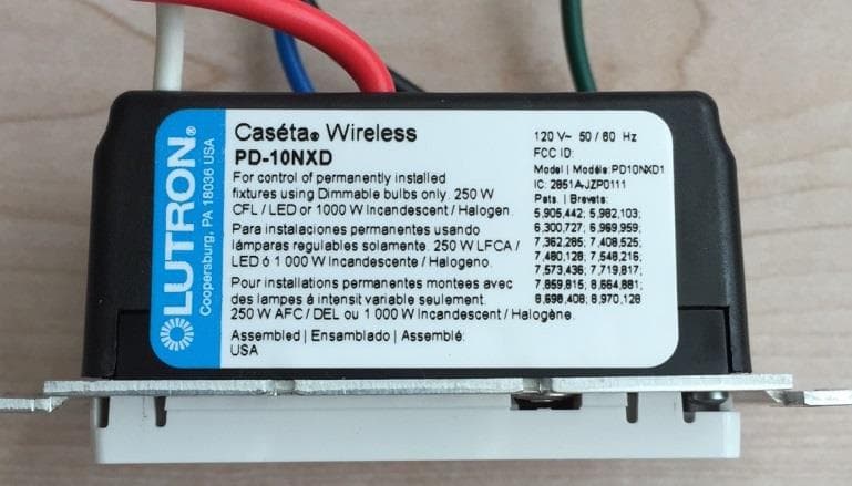
Click to zoom
Application Details
- Equipment Class
- DSR - Part 15 Remote Control/Security Device Transceiver
- Date of Grant
- Apr 08, 2015
- Application Purpose
- Original Equipment
- Date of Application
- Apr 08, 2015
- Equipment Note
- Wireless In-Wall Dimmer Switch
- Frequency Range
- 431.00000000 - 437.00000000
- Country
- United States
Documents & Files
Document Text
Text extracted from the exhibit documents filed with the FCC. Open a document above to read the original.
Users Manual
OFF ON x3 x2 Hold for 6 seconds until LEDs start blinking quick-start guide In-wall dimmer Welcome—and thank you for purchasing a CasétaTM Wireless in-wall dimmer. In order to control your lights from an app or remote, you’ll need to replace an existing switch with a CasétaT Wireless in-wall dimmer. Before you install the dimmer, please watch the installation video at www.casetawireless.com/support We hope you enjoy the convenience of Caséta TM Wireless! NOTE: You can mix and match dimmable LED and CFLs, as well as halogen and incandescent light bulbs, with CasétaTM Wireless dimmers. Dimmable LED and CFL light bulbs vary in their dimming performance. If you’re using these bulbs and they flicker or turn off, please visit www.casetawireless.com/lowend for information on adjusting the dimmer for best bulb performance. For a complete list of compatible dimmable LEDs and CFLs, please visit www.casetawireless.com/bulblist Compatible light bulbs include: Cree ® BA19-08027OMF-12DE26-1U100 CR6-575L EcoSmart ® ECS BR30 W27 FL 120 ECS 20 WW FL 50WE 120 Feit ® A19/OM/LED Philips® 9290002295 Sylvania ® LED12A19/DIM/O/827 LED21PAR38/DIM/P/930/FL30 LED—up to 250 W CFL—up to 250 W Contents supplied Double your warranty In-wall dimmer (PD-10NXD) Tools you’ll need Works with energy efficient dimmable light bulbs: Flat-head screwdriver Wire connectors x5x2 Phillips-head screwdriver Pliers Screws Installation for lights with one wall switch (single pole) Installing your dimmer Using your CasétaT Wireless kit (sold separately) If you have more than one switch controlling the light, this is called a 3-way installation. You will need to buy PJ2-WALL-WH-L01. Please visit www.casetawireless.com/3way for more details. WarNINg: ShOCk hazarD May result in serious injury or death. Turn off power at circuit breaker or fuse before installing. 1 Turn power off at circuit breaker! 1 Press and hold “off” button on dimmer 2 Press and hold “off” button on remote 4 Connect the dimmer 5 Mount the dimmer 6 attach the wallplate 7 Turn power on at circuit breaker 2 remove existing switch from wall Remove the wallplate from switch. 3 remove side sections (if necessary) Remove the switch and pull it away from the wall. * If your switch has more than 3 wires attached, see “Installing Caséta Wireless in a 3-way switch application” video at www.casetawireless.com/3way Bend back and forth. 3 5 1 2 3 4 1 4 6 Ground Ground Ground Optional 7 2 Disconnect all three wires* from the switch. 1 Connect the bare copper (or green) “ground” wire from the wallbox to the green wire on the dimmer using a wire connector. 2 Connect either of the remaining wires from the wallbox to either of the remaining wires on the dimmer using a second wire connector. 3 Connect the remaining wire from the wall to the remaining wire on the dimmer using a third wire connector. 4 If available, connect the white neutral wire. Required for: MLV loads, LED drivers, PHPM-PA, PHPM-3F, GRX-TVI. Do not remove outside side sections on dimmers at the end of gang. Each dimmer has inside side sections removed. Dimmer at middle has all side sections removed. Attach the adapter to the dimmer using the screws provided and snap on the wallplate. ‘snap’ (If you installed the dimmer next to other dimmers or switches, you’ll need to install a wallplate with the correct size/number of openings to accommodate all the devices.) Use the screws provided. Pairing the dimmer and Pico ® remote control Go to www.casetawirless.com/support for additional troubleshooting suggestions. SymptomsProbable cause and action Light does not turn on or in-wall dimmer LEDs do not light up. • Light bulb(s) burned out. • Breaker is OFF or tripped. • Light not properly installed. • Wiring error. • FASS TM switch on the dimmer is in the Off position. Light does not respond to Pico ® remote control. • The dimmer failed to pair with Pico® remote control; see Pairing the dimmer and Pico® remote control. • The dimmer is already at the light level the Pico ® remote control is sending. • The Pico® remote control is outside the 30 ft (9 m) operating range. • The Pico ® remote control battery is low. • The Pico® remote control battery is installed incorrectly. • Bulbs turn off while being dimmed. • Bulbs turn on at high light level but do not turn on at a low light level. • Bulbs flicker or flash when dimmed to a low light level. Verify bulbs are marked dimmable and visit www.casetawireless.com/ lowend for information on adjusting the dimmer for best bulb performance. Love Caséta TM Wireless dimmers? Have ideas for making them better? Tell us what you think and we’ll extend your warranty by 1 year. www.casetawireless.com/register For advanced features, tips for using Caséta TM Wireless dimmers with CFLs and LEDs, the complete CasétaTM Wireless product line, and more, please visit www.casetawireless.com/features Changing the favorite light level on the Pico ® remote control (sold separately) You can use the round “favorite” button on the Pico® remote control to recall a favorite light level. We’ve set it to 50%, but you can change it to any level you like. Favorite replacing light bulbs using FaSSTM Pull the FASSTM switch out on the in-wall dimmer to remove power at the light socket. CaUTION Use only with permanently installed fixtures with dimmable LED, dimmable CFL, halogen, or incandescent,lamps. To avoid overheating and possible damage to other equipment, do not use to control receptacles, motor-driven appliances, or transformer-supplied appliances. Codes Install in accordance with all national and local electrical codes. grounding When no “grounding means” exist in wallbox, the National Electrical Code (NEC®) allows a control to be installed as a replacement if 1) a nonmetallic, noncombustible faceplate is used with nonmetallic attachment screws or 2) the circuit is protected by a ground fault circuit interrupter (GFCI). When installing a control according to these methods, cap or remove green wire before screwing…
Text truncated - open the document above for the full version.
Users Manual
OFF ON x3 x2 Hold for 6 seconds until LEDs start blinking quick-start guide In-wall dimmer Welcome—and thank you for purchasing a CasétaTM Wireless in-wall dimmer. In order to control your lights from an app or remote, you’ll need to replace an existing switch with a CasétaT Wireless in-wall dimmer. Before you install the dimmer, please watch the installation video at www.casetawireless.com/support We hope you enjoy the convenience of Caséta TM Wireless! NOTE: You can mix and match dimmable LED and CFLs, as well as halogen and incandescent light bulbs, with CasétaTM Wireless dimmers. Dimmable LED and CFL light bulbs vary in their dimming performance. If you’re using these bulbs and they flicker or turn off, please visit www.casetawireless.com/lowend for information on adjusting the dimmer for best bulb performance. For a complete list of compatible dimmable LEDs and CFLs, please visit www.casetawireless.com/bulblist Compatible light bulbs include: Cree ® BA19-08027OMF-12DE26-1U100 CR6-575L EcoSmart ® ECS BR30 W27 FL 120 ECS 20 WW FL 50WE 120 Feit ® A19/OM/LED Philips® 9290002295 Sylvania ® LED12A19/DIM/O/827 LED21PAR38/DIM/P/930/FL30 LED—up to 250 W CFL—up to 250 W Contents supplied Double your warranty In-wall dimmer (PD-10NXD) Tools you’ll need Works with energy efficient dimmable light bulbs: Flat-head screwdriver Wire connectors x5x2 Phillips-head screwdriver Pliers Screws Installation for lights with one wall switch (single pole) Installing your dimmer Using your CasétaT Wireless kit (sold separately) If you have more than one switch controlling the light, this is called a 3-way installation. You will need to buy PJ2-WALL-WH-L01. Please visit www.casetawireless.com/3way for more details. WarNINg: ShOCk hazarD May result in serious injury or death. Turn off power at circuit breaker or fuse before installing. 1 Turn power off at circuit breaker! 1 Press and hold “off” button on dimmer 2 Press and hold “off” button on remote 4 Connect the dimmer 5 Mount the dimmer 6 attach the wallplate 7 Turn power on at circuit breaker 2 remove existing switch from wall Remove the wallplate from switch. 3 remove side sections (if necessary) Remove the switch and pull it away from the wall. * If your switch has more than 3 wires attached, see “Installing Caséta Wireless in a 3-way switch application” video at www.casetawireless.com/3way Bend back and forth. 3 5 1 2 3 4 1 4 6 Ground Ground Ground Optional 7 2 Disconnect all three wires* from the switch. 1 Connect the bare copper (or green) “ground” wire from the wallbox to the green wire on the dimmer using a wire connector. 2 Connect either of the remaining wires from the wallbox to either of the remaining wires on the dimmer using a second wire connector. 3 Connect the remaining wire from the wall to the remaining wire on the dimmer using a third wire connector. 4 If available, connect the white neutral wire. Required for: MLV loads, LED drivers, PHPM-PA, PHPM-3F, GRX-TVI. Do not remove outside side sections on dimmers at the end of gang. Each dimmer has inside side sections removed. Dimmer at middle has all side sections removed. Attach the adapter to the dimmer using the screws provided and snap on the wallplate. ‘snap’ (If you installed the dimmer next to other dimmers or switches, you’ll need to install a wallplate with the correct size/number of openings to accommodate all the devices.) Use the screws provided. Pairing the dimmer and Pico ® remote control Go to www.casetawirless.com/support for additional troubleshooting suggestions. SymptomsProbable cause and action Light does not turn on or in-wall dimmer LEDs do not light up. • Light bulb(s) burned out. • Breaker is OFF or tripped. • Light not properly installed. • Wiring error. • FASS TM switch on the dimmer is in the Off position. Light does not respond to Pico ® remote control. • The dimmer failed to pair with Pico® remote control; see Pairing the dimmer and Pico® remote control. • The dimmer is already at the light level the Pico ® remote control is sending. • The Pico® remote control is outside the 30 ft (9 m) operating range. • The Pico ® remote control battery is low. • The Pico® remote control battery is installed incorrectly. • Bulbs turn off while being dimmed. • Bulbs turn on at high light level but do not turn on at a low light level. • Bulbs flicker or flash when dimmed to a low light level. Verify bulbs are marked dimmable and visit www.casetawireless.com/ lowend for information on adjusting the dimmer for best bulb performance. Love Caséta TM Wireless dimmers? Have ideas for making them better? Tell us what you think and we’ll extend your warranty by 1 year. www.casetawireless.com/register For advanced features, tips for using Caséta TM Wireless dimmers with CFLs and LEDs, the complete CasétaTM Wireless product line, and more, please visit www.casetawireless.com/features Changing the favorite light level on the Pico ® remote control (sold separately) You can use the round “favorite” button on the Pico® remote control to recall a favorite light level. We’ve set it to 50%, but you can change it to any level you like. Favorite replacing light bulbs using FaSSTM Pull the FASSTM switch out on the in-wall dimmer to remove power at the light socket. CaUTION Use only with permanently installed fixtures with dimmable LED, dimmable CFL, halogen, or incandescent,lamps. To avoid overheating and possible damage to other equipment, do not use to control receptacles, motor-driven appliances, or transformer-supplied appliances. Codes Install in accordance with all national and local electrical codes. grounding When no “grounding means” exist in wallbox, the National Electrical Code (NEC®) allows a control to be installed as a replacement if 1) a nonmetallic, noncombustible faceplate is used with nonmetallic attachment screws or 2) the circuit is protected by a ground fault circuit interrupter (GFCI). When installing a control according to these methods, cap or remove green wire before screwing…
Text truncated - open the document above for the full version.
External Photos
FCC ID: JPZ0111 IC ID: 2851A-JPZ0111 FCC ID: JPZ0111 IC ID: 2851A-JPZ0111
External Photos
FCC ID: JPZ0111 IC ID: 2851A-JPZ0111 FCC ID: JPZ0111 IC ID: 2851A-JPZ0111
ID Label/Location Info
FCC ID: JPZ0111 IC ID: 2851A-JPZ0111
ID Label/Location Info
FCC ID: JPZ0111 IC ID: 2851A-JPZ0111
Internal Photos
FCC ID: JPZ0111 IC ID: 2851A-JPZ0111
Internal Photos
FCC ID: JPZ0111 IC ID: 2851A-JPZ0111
Test Report
NVLAP Lab code: 100414-0 FCC 47 CFR PART 15 SUBPART C CERTIFICATION TEST REPORT FOR Wireless In-Wall Dimmer Switch MODEL NUMBER: PD10NXD1 FCC ID: JPZ0111 REPORT NUMBER: 10703597 ISSUE DATE: April 7, 2015 Prepared for LUTRON ELECTRONICS CO INC. 7200 SUTER RD COOPERSBURG PA, 18036, USA Prepared by UL LLC 333 Pfingsten Rd. Northbrook, IL 60062 TEL: (847) 272-8800 REPORT NO: 10703597 DATE: April 7, 2015 FCC ID: JPZ0111 Page 2 of 38 UL LLC FORM NO: CCSUP4701I 333 Pfingsten Rd., Northbrook, IL 60062, USA TEL: (847) 272-8800 This report shall not be reproduced except in full, without the written approval of UL LLC Revision History Rev. Issue Date Revisions Revised By -- April 7, 2015 Initial Issue BM REPORT NO: 10703597 DATE: April 7, 2015 FCC ID: JPZ0111 Page 3 of 38 UL LLC FORM NO: CCSUP4701I 333 Pfingsten Rd., Northbrook, IL 60062, USA TEL: (847) 272-8800 This report shall not be reproduced except in full, without the written approval of UL LLC TABLE OF CONTENTS 1. ATTESTATION OF TEST RESULTS ........................................................................................................... 4 2. TEST METHODOLOGY ................................................................................................................................ 5 3. FACILITIES AND ACCREDITATION ........................................................................................................... 5 4. CALIBRATION AND UNCERTAINTY .......................................................................................................... 5 4.1. MEASURING INSTRUMENT CALIBRATION ........................................................................................ 5 4.2. SAMPLE CALCULATION ....................................................................................................................... 5 4.3. MEASUREMENT UNCERTAINTY ......................................................................................................... 5 5. EQUIPMENT UNDER TEST ......................................................................................................................... 6 5.1. DESCRIPTION OF EUT ......................................................................................................................... 6 5.2. DESCRIPTION OF AVAILABLE ANTENNAS ........................................................................................ 6 5.3. SOFTWARE AND FIRMWARE .............................................................................................................. 6 5.4. WORST-CASE CONFIGURATION AND MODE ................................................................................... 6 5.5. MODIFICATIONS ................................................................................................................................... 6 5.6. DESCRIPTION OF TEST SETUP .......................................................................................................... 7 6. TEST AND MEASUREMENT EQUIPMENT ................................................................................................. 9 7. ANTENNA PORT TEST RESULTS ............................................................................................................ 10 7.1. 20 dB AND 99% BW ............................................................................................................................ 10 7.2. DUTY CYCLE ....................................................................................................................................... 14 7.3. TRANSMISSION TIME ........................................................................................................................ 17 8. RADIATED EMISSION TEST RESULTS ................................................................................................... 18 8.1. TX RADIATED SPURIOUS EMISSION ............................................................................................... 18 8.2. RX & DIGITAL EMISSION ................................................................................................................... 24 9. AC MAINS LINE CONDUCTED EMISSIONS ............................................................................................. 27 10. SETUP PHOTOS ..................................................................................................................................... 35 REPORT NO: 10703597 DATE: April 7, 2015 FCC ID: JPZ0111 Page 4 of 38 UL LLC FORM NO: CCSUP4701I 333 Pfingsten Rd., Northbrook, IL 60062, USA TEL: (847) 272-8800 This report shall not be reproduced except in full, without the written approval of UL LLC 1. ATTESTATION OF TEST RESULTS COMPANY NAME: LUTRON ELECTRONICS CO INC. 7200 SUTER RD COOPERSBURG, PA, 18036, USA EUT DESCRIPTION: Wireless In-Wall Dimmer Switch MODEL: PD10NXD1 SERIAL NUMBER: Non-Serialized DATE TESTED: April 1, 2015 – April 6, 2015 APPLICABLE STANDARDS STANDARD TEST RESULTS FCC PART 15 SUBPART C Pass UL LLC tested the above equipment in accordance with the requirements set forth in the above standards. All indications of Pass/Fail in this report are opinions expressed by UL LLC based on interpretations and/or observations of test results. Measurement Uncertainties were not taken into account and are published for informational purposes only. The test results show that the equipment tested is capable of demonstrating compliance with the requirements as documented in this report. Note: The results documented in this report apply only to the tested sample, under the conditions and modes of operation as described herein. This document may not be altered or revised in any way unless done so by UL LLC and all revisions are duly noted in the revisions section. Any alteration of this document not carried out by UL LLC will constitute fraud and shall nullify the document. This report must not be used by the client to claim product certification, approval, or endorsement by NVLAP, NIST, any agency of the Federal Government, or any agency of a…
Text truncated - open the document above for the full version.
Test Report
NVLAP Lab code: 100414-0 FCC 47 CFR PART 15 SUBPART C CERTIFICATION TEST REPORT FOR Wireless In-Wall Dimmer Switch MODEL NUMBER: PD10NXD1 FCC ID: JPZ0111 REPORT NUMBER: 10703597 ISSUE DATE: April 7, 2015 Prepared for LUTRON ELECTRONICS CO INC. 7200 SUTER RD COOPERSBURG PA, 18036, USA Prepared by UL LLC 333 Pfingsten Rd. Northbrook, IL 60062 TEL: (847) 272-8800 REPORT NO: 10703597 DATE: April 7, 2015 FCC ID: JPZ0111 Page 2 of 38 UL LLC FORM NO: CCSUP4701I 333 Pfingsten Rd., Northbrook, IL 60062, USA TEL: (847) 272-8800 This report shall not be reproduced except in full, without the written approval of UL LLC Revision History Rev. Issue Date Revisions Revised By -- April 7, 2015 Initial Issue BM REPORT NO: 10703597 DATE: April 7, 2015 FCC ID: JPZ0111 Page 3 of 38 UL LLC FORM NO: CCSUP4701I 333 Pfingsten Rd., Northbrook, IL 60062, USA TEL: (847) 272-8800 This report shall not be reproduced except in full, without the written approval of UL LLC TABLE OF CONTENTS 1. ATTESTATION OF TEST RESULTS ........................................................................................................... 4 2. TEST METHODOLOGY ................................................................................................................................ 5 3. FACILITIES AND ACCREDITATION ........................................................................................................... 5 4. CALIBRATION AND UNCERTAINTY .......................................................................................................... 5 4.1. MEASURING INSTRUMENT CALIBRATION ........................................................................................ 5 4.2. SAMPLE CALCULATION ....................................................................................................................... 5 4.3. MEASUREMENT UNCERTAINTY ......................................................................................................... 5 5. EQUIPMENT UNDER TEST ......................................................................................................................... 6 5.1. DESCRIPTION OF EUT ......................................................................................................................... 6 5.2. DESCRIPTION OF AVAILABLE ANTENNAS ........................................................................................ 6 5.3. SOFTWARE AND FIRMWARE .............................................................................................................. 6 5.4. WORST-CASE CONFIGURATION AND MODE ................................................................................... 6 5.5. MODIFICATIONS ................................................................................................................................... 6 5.6. DESCRIPTION OF TEST SETUP .......................................................................................................... 7 6. TEST AND MEASUREMENT EQUIPMENT ................................................................................................. 9 7. ANTENNA PORT TEST RESULTS ............................................................................................................ 10 7.1. 20 dB AND 99% BW ............................................................................................................................ 10 7.2. DUTY CYCLE ....................................................................................................................................... 14 7.3. TRANSMISSION TIME ........................................................................................................................ 17 8. RADIATED EMISSION TEST RESULTS ................................................................................................... 18 8.1. TX RADIATED SPURIOUS EMISSION ............................................................................................... 18 8.2. RX & DIGITAL EMISSION ................................................................................................................... 24 9. AC MAINS LINE CONDUCTED EMISSIONS ............................................................................................. 27 10. SETUP PHOTOS ..................................................................................................................................... 35 REPORT NO: 10703597 DATE: April 7, 2015 FCC ID: JPZ0111 Page 4 of 38 UL LLC FORM NO: CCSUP4701I 333 Pfingsten Rd., Northbrook, IL 60062, USA TEL: (847) 272-8800 This report shall not be reproduced except in full, without the written approval of UL LLC 1. ATTESTATION OF TEST RESULTS COMPANY NAME: LUTRON ELECTRONICS CO INC. 7200 SUTER RD COOPERSBURG, PA, 18036, USA EUT DESCRIPTION: Wireless In-Wall Dimmer Switch MODEL: PD10NXD1 SERIAL NUMBER: Non-Serialized DATE TESTED: April 1, 2015 – April 6, 2015 APPLICABLE STANDARDS STANDARD TEST RESULTS FCC PART 15 SUBPART C Pass UL LLC tested the above equipment in accordance with the requirements set forth in the above standards. All indications of Pass/Fail in this report are opinions expressed by UL LLC based on interpretations and/or observations of test results. Measurement Uncertainties were not taken into account and are published for informational purposes only. The test results show that the equipment tested is capable of demonstrating compliance with the requirements as documented in this report. Note: The results documented in this report apply only to the tested sample, under the conditions and modes of operation as described herein. This document may not be altered or revised in any way unless done so by UL LLC and all revisions are duly noted in the revisions section. Any alteration of this document not carried out by UL LLC will constitute fraud and shall nullify the document. This report must not be used by the client to claim product certification, approval, or endorsement by NVLAP, NIST, any agency of the Federal Government, or any agency of a…
Text truncated - open the document above for the full version.
Test Setup Photos
REPORT NO: 10703597 DATE: April 7, 2015 FCC ID: JPZ0111 IC: 2851A-JPZ0111 Page 35 of 38 UL LLC FORM NO: CCSUP4701I 333 Pfingsten Rd., Northbrook, IL 60062, USA TEL: (847) 272-8800 This report shall not be reproduced except in full, without the written approval of UL LLC 10. SETUP PHOTOS NEAR FILED MEASUREMENTS REPORT NO: 10703597 DATE: April 7, 2015 FCC ID: JPZ0111 IC: 2851A-JPZ0111 Page 36 of 38 UL LLC FORM NO: CCSUP4701I 333 Pfingsten Rd., Northbrook, IL 60062, USA TEL: (847) 272-8800 This report shall not be reproduced except in full, without the written approval of UL LLC RADIATED EMISSION CONFIGURATION BELOW 1GHz REPORT NO: 10703597 DATE: April 7, 2015 FCC ID: JPZ0111 IC: 2851A-JPZ0111 Page 37 of 38 UL LLC FORM NO: CCSUP4701I 333 Pfingsten Rd., Northbrook, IL 60062, USA TEL: (847) 272-8800 This report shall not be reproduced except in full, without the written approval of UL LLC RADIATED EMISSION CONFIGURATION ABOVE 1GHz REPORT NO: 10703597 DATE: April 7, 2015 FCC ID: JPZ0111 IC: 2851A-JPZ0111 Page 38 of 38 UL LLC FORM NO: CCSUP4701I 333 Pfingsten Rd., Northbrook, IL 60062, USA TEL: (847) 272-8800 This report shall not be reproduced except in full, without the written approval of UL LLC Conducted Emissions END OF REPORT
Test Setup Photos
REPORT NO: 10703597 DATE: April 7, 2015 FCC ID: JPZ0111 IC: 2851A-JPZ0111 Page 35 of 38 UL LLC FORM NO: CCSUP4701I 333 Pfingsten Rd., Northbrook, IL 60062, USA TEL: (847) 272-8800 This report shall not be reproduced except in full, without the written approval of UL LLC 10. SETUP PHOTOS NEAR FILED MEASUREMENTS REPORT NO: 10703597 DATE: April 7, 2015 FCC ID: JPZ0111 IC: 2851A-JPZ0111 Page 36 of 38 UL LLC FORM NO: CCSUP4701I 333 Pfingsten Rd., Northbrook, IL 60062, USA TEL: (847) 272-8800 This report shall not be reproduced except in full, without the written approval of UL LLC RADIATED EMISSION CONFIGURATION BELOW 1GHz REPORT NO: 10703597 DATE: April 7, 2015 FCC ID: JPZ0111 IC: 2851A-JPZ0111 Page 37 of 38 UL LLC FORM NO: CCSUP4701I 333 Pfingsten Rd., Northbrook, IL 60062, USA TEL: (847) 272-8800 This report shall not be reproduced except in full, without the written approval of UL LLC RADIATED EMISSION CONFIGURATION ABOVE 1GHz REPORT NO: 10703597 DATE: April 7, 2015 FCC ID: JPZ0111 IC: 2851A-JPZ0111 Page 38 of 38 UL LLC FORM NO: CCSUP4701I 333 Pfingsten Rd., Northbrook, IL 60062, USA TEL: (847) 272-8800 This report shall not be reproduced except in full, without the written approval of UL LLC Conducted Emissions END OF REPORT
Contact Information
Applicant
Daniel Schlegel(Standards Compliance Supervisor)
Technical Contact
Non-Technical Contact
UL LLCBart Mucha
[email protected]8476641216
Test Firm
UL LLCRick Titus
Technical Specifications
| # | Rule Parts | Frequency Range | Power Output |
|---|---|---|---|
| 1 | 15.231 | 431 MHz - 437 MHz | - |
Other Applications from Lutron Electronics Company Inc
JPZ0161
Sep 03, 2026Wireless Interface
Equipment Class
DTS - Digital Transmission SystemJPZ0159
Aug 12, 2026Wireless Processor
Equipment Class
DTS - Digital Transmission SystemJPZ0158
Jul 27, 2026Copy of Wireless Processor
Equipment Class
DTS - Digital Transmission SystemJPZ0157
Mar 26, 2026LED Downlight
Equipment Class
DTS - Digital Transmission SystemJPZ0155
Sep 30, 2024LED Lighting Controller
Equipment Class
DTS - Digital Transmission System