JPZ0129Wireless Processor
Lutron Electronics Company Inc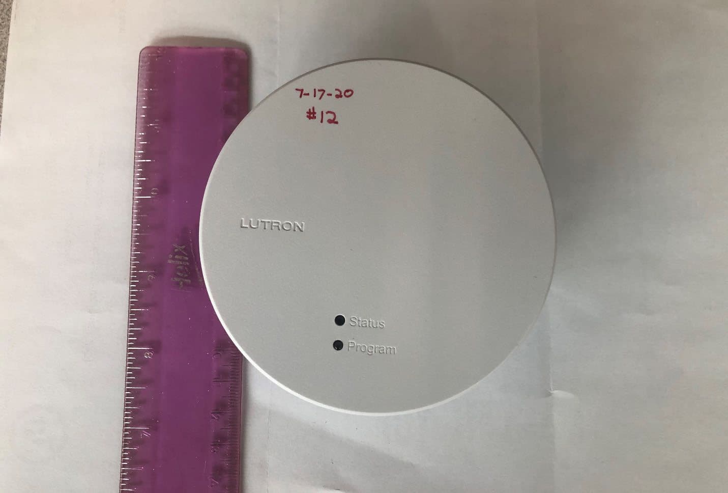
Click to zoom
Application Details
- Equipment Class
- DSR - Part 15 Remote Control/Security Device Transceiver
- Date of Grant
- Jan 07, 2021
- Application Purpose
- Original Equipment
- Date of Application
- Jan 07, 2021
- Equipment Note
- Wireless Processor
- Frequency Range
- 431.50000000 - 436.60000000
- Country
- United States
Documents & Files
Document Text
Text extracted from the exhibit documents filed with the FCC. Open a document above to read the original.
Users Manual
P/N 043522 Rev. A 01/2020 – The gateway requires at least one HomeWorks QSX Processor. Refer to the installation instructions of the HomeWorks QSX Processor for setup and other information. The Clear Connect – T ype X Gateway must be powered by an approved LPS/SEL V PoE power supply compliant to IEEE 802.3af 2003 or 802.3at 2009. Included Components Gateway Recess-mount adaptor Surface-mount adaptor Ladder Drill Pencil Philips head screwdriver Tools You May Need Components (not included) Mud ring 22 in (70 mm) Hole saw 31 in to 3` in (83 mm to 89 mm) Limited Warranty For limited warranty information, please visit http://www.lutron.com/TechnicalDocumentLibrary/043492.pdf )Lutron, Lutron, Quantum, HomeWorks, and Clear Connect are trademarks or registered trademarks of Lutron Electronics Co., Inc. in the US and/or other countries. ©2019 Lutron Electronics Co., Inc. Customer Assistance For questions concerning the installation or operation of this product, call the Lutron Customer Assistance. Please provide exact model number when calling. FCC/IC/IFT Information This device complies with part 15 of the FCC Rules and Industry Canada license-exempt RSS standard(s). Operation is subject to the following two conditions: (1) This device may not cause interference, and (2) this device must accept any interference, including interference that may cause undesired operation. Modifications not expressly approved by Lutron Electronics Co., Inc. could void the user’s authority to operate this equipment. Note: This equipment has been tested and found to comply with the limits for a Class B digital device, pursuant to part 15 of the FCC Rules. These limits are designed to provide reasonable protection against harmful interference in a residential installation. This equipment generates, uses and can radiate radio frequency energy and, if not installed and used in accordance with the instructions, may cause harmful interference to radio communications. However, there is no guarantee that interference will not occur in a particular installation. If this equipment does cause harmful interference to radio or television reception, which can be determined by turning the equipment off and on, the user is encouraged to try to correct the interference by one or more of the following measures: – Reorient or relocate the receiving antenna. – Increase the separation between the equipment and receiver. – Connect the equipment into an outlet on a circuit different from that to which the receiver is connected. – Consult the dealer or an experienced radio/TV technici an for help. This equipment complies with FCC/ISED radiation expo sure limits set forth for an uncontrolled environment. The user should avoid prolonged exposure within 20cm o f the antenna, which may exceed the FCC/ISED radio frequency exposure limits. This Class B digital apparatus complies with Canadian ICES-003. www.lutron.com/supportU.S.A. and Canada 1.844.LUTRON1 Mexico 8am – 8pm ET +1.888.235.2910 Product Overview Status LED – Provide Gateway Feedback Green = Normal Operation Blue = Firmware upgrade in process Red - Error Program Button Used to factory reset gateway and to associate into a system Installation Choose a location to mount the Gateway so that it is centrally located in relationship to the other Clear Connect – Type X devices. A minimum of two or more Clear Connect – Type X devices must be within 25 ft (7.6 m)* of the Gateway. See Lutron application note P/N 048745 for more information on mounting location requirements for the Gateway. A maximum of 16 total Gateways and wired Processors can be on one system. Clear Connect Gateway – Type X must be mounted 5 ft (1.5 m) away from wireless interference sources like microwaves, Wireless Access Points (WAPs) etc. PoE wiring must be kept internal to the building. Do not run PoE wiring outdoors or install the gateway in metallic enclosures. 3 1 ⁄4 in to 3 1 ⁄2 in (83 mm to 89 mm) Recess-mount adaptor Junction box Mud ring Surface-mount adaptor Install adaptor Install mud ring OR Recess-mount adaptor Select the mounting adaptor for your installation. Each Clear Connect Gateway – Type X comes with a recess-mount adaptor and a surface-mount adaptor. To adaptor To mud ring Surface-mount adaptor Add the gateway into the HomeWorks Designer software. Note: Requires HomeWorks Designer software 16.0 or later. System Setup SymptomProbable Causes and Solutions Unit does not power onA PoE Switch is not being used or commissioned as a PoE Switch Other end of the Ethernet cable is not connected to the PoE Switch Unit can not be found in software The Ethernet cable is not directly connected to the Ethernet switch that the wired processor is using Model is not supported (Quantum / myRoom vs. HomeWorks) Ethernet run is longer than the supported 328 ft (100 m) and a PoE extender is needed Unit does not control surrounding lights Out of wireless range Gateway lost power / Ethernet wire run too long and PoE booster is required Troubleshooting Mode/ErrorLED Pattern Description Normal OperationStatus LED blinks Green every 10 seconds Software UpdateStatus LED blinks Blue ErrorStatus LED - solid Red Processor IdentifyStatus LED blinks Green rapidly LED Diagnostics HomeWorks Clear Connect Gateway – Type X HQP7-RF-2, HQREP-RF RR-PROC3, RR-REP3 48 V- 100 mA English Installation Instructions Please Read Before Installing Step 1 — Choose a Location to Install L 1 +24COM L 2COM CCI V+ COM MUXMUX 0,28 in 7 mm L1L2 ===LED | DEL T x R x 4,4 in-lb 0,5 N • m V+ COM MUXMUX QSX Processor Island Screen Bay 1 Bay 2 Bay 3 71 ft max (21.6 m) 25 ft max (7.6 m) Equipment Room Kitchen Powder Room Dining Room Walk-in Closet Master Bedroom Master Bath Coat Closet Home Theatre PoE Switch CAT5e Minimum 328 ft (100 m) max applies to both wires in the dashed box Step 2 — Provide opening for Adaptor Step 3 — Install Adaptor or Mud Ring into Ceiling Step 4 — Plug in PoE and Attach Gateway to Adaptor OR Step 2a Note: Each Clear Connect – Type X devi…
Text truncated - open the document above for the full version.
Cover Letter(s)
Date: 13 November 2020 Federal Communications Commission 7435 Oakland Mills Road Columbia MD 21046 c.c. UL Verification Services Certification Division 47173 Benicia Street Fremont, CA 94538, USA To whom it may concern: I, the undersigned, hereby authorize UL LLC to act on our behalf in all manners relating to application for equipment authorization, including signing of all documents relating to these matters. Any and all acts carried out by UL LLC on our behalf shall have the same effect as acts of our own. I, the undersigned, hereby certify that we are not subject to a denial of federal benefits, that includes FCC benefits, pursuant to Section 5301 of the Anti-Drug Abuse Act of 1988, 21 U.S.C. 853(a). In authorizing UL LLC as our agent, we still recognize that we are responsible to: a) comply with the relevant provisions of the certification program; b) make all necessary arrangements for the conduct of the evaluation, including provision for examining documentation and access to all areas, records (including internal audit reports) and personnel for the purposes of evaluation (e.g. testing, inspection, assessment, surveillance, reassessment) and resolution of complaints; c) make claims regarding certification only in respect of the scope for which certification has been granted; d) do not use our product certification in such a manner as to bring the Certification Division into disrepute and not make any statement regarding our product certification which the Certification Division may consider misleading or unauthorized; e) upon suspension or cancellation of certification, discontinue use of all advertising matter that contains any reference thereto and return any certification documents as required by the Certification Division; f) use certification only to indicate the products are certified as being in conformity with specified standards; g) endeavor to ensure that no certificate or report nor any part thereof is used in a misleading manner; h) ensure that any reference to our product certification in communication media such as documents, brochures or advertising, complies with the requirements of the Certification Division; i) keep a record of all complaints made known to the us relating to the product’s compliance with requirements of the relevant standard and to make these records available to the Certification Division when requested; j) take appropriate action with respect to such complaints and any deficiencies found in products or services that affect compliance with the requirements for certification; k) document the actions taken. This authorization is valid until further written notice from the applicant. Sincerely Yours, Robert Spehalski Engineering Leader Lutron Electronics Co., Inc.
Cover Letter(s)
Federal Communications Commission 7435 Oakland Mills Road Columbia MD 21046 13 November 2020 Subject: Long Term Request for Confidentiality – JPZ0129 Dear Sir or Madam: This letter is to formally request long term confidentiality, per the FCC Rules 47 CFR 0.457 and 0.459, for materials or information submitted to the Commission to be withheld from public inspection. For all models in this submission, the following items are Lutron Electronics Co., Inc. confidential information that must be from public inspection by potential competitors to protect our business. 1. Schematic 2. Operation Description 3. Bill of Materials 4. Block Diagram Thank you for your cooperation. Sincerely, Robert Spehalski Engineering Leader F ederal Communications Commission 7435 Oakland Mills Road Columbia MD 21046 13 N ovember 2020 Subject: Short Term Request for Confidentiality – JPZ0129 Dear Sir or Madam: This letter is to formally request short term confidentiality, per the FCC Rules 47 CFR 0.457 and 0.459, for materials or information submitted to the Commission to be withheld from public inspection. F or all models in this submission, Lutron Electronics Co., Inc. requests that materials or information submitted to the Commission be withheld from public inspection for 180 days from 13 November 2020. 1.Internal Photos 2.External Photos 3. Test Setup Photos 4.User Manual Thank you for your cooperation. S incerely, R obert Spehalski Engineering Leader
Cover Letter(s)
LUTRON ELECTRONICS CO., INC. November 2020 Model Difference Letter For product certification 2851A-JPZ0129 the following Product Marketing Names are present: HQP7-RF-2 HQREP-RF RR-PROC3 RR-REP3 These devices all utilize the same PCB and wireless circuitry hardware. HQP7-RF-2 – this is the tested model number HQREP-RF – this is identical in construction to the tested model number with some of the logic circuitry used for data processing removed. The device has the same antenna path and wireless operation as the tested model. RR-PROC3-This device is identical to the tested model number but marked differently for marketing purposes for use with another Lutron lighting control system RR-REP3- This device is identical in construction to the tested model number with some of the logic circuitry used for data processing removed. The device has the same antenna path and wireless operation as the tested model. It is also marked differently for marketing purposes for use with another Lutron lighting control system. List of changes removing the data processing: Main processor and support chips for the main processor are removed (DDRAM, EPROM) This micro is only responsible for the logic processing of the device and does not affect the wireless circuitry. Co-processors which handle the 2.4GHz and 434MHz transceivers and support circuitry are still placed in the product and tied together through UART.
ID Label/Location Info
Model Number 48 V- 100 mA lutron.com +1.844.LUTRON1 Assembled | Ensamblado | Assemblé : U.S.A. | E.U.A. | É.-U. This device complies with part 15 of the FCC Rules. Operation is subject to the following two conditions: (1) This device may not cause interference. (2) This device must accept any interference, including interference that may cause undesired operation. CAN ICES-3 (B)/NMB-3(B) Serial #: 00000000 Ethernet MAC: ab:12:cd:34:ef IC: 2851A-JPZ0129 FCC ID: JPZ0129 HVIN: JWP1
Internal Photos
PCB trace F antenna Chip Antenna 434MHz Monopole antenna
Test Report
NVLAP LAB CODE 200246-0 FCC CFR47 PART 15 SUBPART C ISED CANADA RSS-210 ISSUE 10 TEST REPORT FOR WIRELESS PROCESSOR MODEL NUMBER: HQP7-RF-2, HQREP-RF, RR-PROC3, RR-REP3 FCC ID: JPZ0129 IC: 2851A-JPZ0129 REPORT NUMBER: R13413705-E1 ISSUE DATE: 2020-12-09 Prepared for LUTRON ELECTRONICS CO. INC. 7200 SUTER ROAD COOPERSBURG, PA 18036-1249, U.S.A. Prepared by UL LLC 12 LABORATORY DR. RESEARCH TRIANGLE PARK, NC 27709 USA TEL: (919) 549-1400 REPORT NO: R13413705-E1 DATE: 2020-12-09 FCC ID: JPZ0129 IC: 2851A-JPZ0129 Page 2 of 38 UL LLC FORM NO: 03-EM-F00858 12 Laboratory Dr., RTP, NC 27709 TEL: (919) 549-1400 This report shall not be reproduced except in full, without the written approval of UL LLC. REVISION HISTORY Ver. Issue Date Revisions Revised By 1 2020-09-22 Initial Issue Brian T. Kiewra 2 2020-10-07 Added Simultaneous Transmitter data Mike Antola 3 2020-11-11 Removed setup photos for submission. Brian T. Kiewra 4 2020-11-30 Updated low channel spurious limit; removed simultaneous transmitter data; updated test procedure for Section 9. Mike Antola 5 2020-12-09 Revised model number Brian T. Kiewra REPORT NO: R13413705-E1 DATE: 2020-12-09 FCC ID: JPZ0129 IC: 2851A-JPZ0129 Page 3 of 38 UL LLC FORM NO: 03-EM-F00858 12 Laboratory Dr., RTP, NC 27709 TEL: (919) 549-1400 This report shall not be reproduced except in full, without the written approval of UL LLC. TABLE OF CONTENTS REVISION HISTORY ..................................................................................................................2 TABLE OF CONTENTS .............................................................................................................3 1. ATTESTATION OF TEST RESULTS ..................................................................................4 2. TEST METHODOLOGY ......................................................................................................5 3. FACILITIES AND ACCREDITATION ..................................................................................5 4. DECISION RULES AND MEASUREMENT UNCERTAINTY ...............................................6 4.1. METROLOGICAL TRACEABILITY ...............................................................................6 4.2. DECISION RULES ........................................................................................................6 4.3. MEASUREMENT UNCERTAINTY ................................................................................6 4.4. SAMPLE CALCULATION .............................................................................................6 5. EQUIPMENT UNDER TEST ................................................................................................7 5.1. DESCRIPTION OF EUT ...............................................................................................7 5.2. DESCRIPTION OF AVAILABLE ANTENNAS ...............................................................7 5.3. SOFTWARE AND FIRMWARE .....................................................................................7 5.4. WORST-CASE CONFIGURATION AND MODE ...........................................................7 5.5. MODIFICATIONS .........................................................................................................7 5.6. DESCRIPTION OF TEST SETUP .................................................................................8 6. TEST AND MEASUREMENT EQUIPMENT ........................................................................9 7. ANTENNA PORT TEST RESULTS ...................................................................................11 7.1. 20 dB AND 99% BW ...................................................................................................11 7.2. DUTY CYCLE .............................................................................................................14 7.3. TRANSMISSION TIME ...............................................................................................17 8. RADIATED EMISSION TEST RESULTS...........................................................................18 8.1. TX RADIATED SPURIOUS EMISSION ......................................................................18 8.1.1. FUNDAMENTAL MEASUREMENTS ...................................................................21 8.1.2. TX SPURIOUS EMISSIONS (0.009-30MHz – WORST CASE) ............................22 8.1.3. HARMONICS AND TX SPURIOUS EMISSIONS (30 - 5000MHz) .......................23 9. AC MAINS LINE CONDUCTED EMISSIONS ....................................................................35 10. SETUP PHOTOS ...............................................................................................................38 END OF TEST REPORT ..........................................................................................................38 REPORT NO: R13413705-E1 DATE: 2020-12-09 FCC ID: JPZ0129 IC: 2851A-JPZ0129 Page 4 of 38 UL LLC FORM NO: 03-EM-F00858 12 Laboratory Dr., RTP, NC 27709 TEL: (919) 549-1400 This report shall not be reproduced except in full, without the written approval of UL LLC. 1. ATTESTATION OF TEST RESULTS COMPANY NAME: Lutron Electronics Co. Inc. 7200 Suter Road Coopersburg, PA 18036-1249, U.S.A. EUT DESCRIPTION: Wireless Processor MODEL: HQP7-RF-2 , HQREP-RF, RR-PROC3, RR-REP3 SERIAL NUMBER: 02D5CD8E, 02D5CD87 RECEIVED DATE: 2020-08-03 DATE TESTED: 2020-09-11 to 2020-09-13 APPLICABLE STANDARDS STANDARD TEST RESULTS FCC PART 15 SUBPART C Complies ISED CANADA RSS-210 Issue 10 Complies ISED CANADA RSS-GEN Issue 5 + Amendment 1 Complies UL LLC tested the above equipment in accordance with the requirements set forth in the above standards. The test results show that the equipment tested is capable of demonstrating compliance with the requirements as documented in this report. The results documented in this report apply only to the tested sample, under the conditions and modes of operation as described herein. It is the manufacturer's responsibility to assure that additi…
Text truncated - open the document above for the full version.
Test Setup Photos
NVLAP Lab code: 200246-0 PHOTOS EXHIBIT Report Number. : R13413705-EP2 Applicant : Lutron Electronics Co Inc. 7200 Suter Rd. Coopersburg, PA, 18036-1249, USA Model : HQP7-RF-2, HQREP-RF, RR-PROC3, RR-REP3 FCC ID : JPZ0129 IC : 2851A-JPZ0129 EUT Description : Wireless Processor Test Standard(s) : FCC 47 CFR PART 15 SUBPART C ISED RSS-210 ISSUE 10 Date Of Issue: 2020-11-11 Prepared by: UL LLC 12 Laboratory Dr. Research Triangle Park, NC 27709 U.S.A. TEL: (919) 549-1400 REPORT NO: R13413705-EP1 DATE: 2020-11-11 FCC ID: JPZ0129 IC: 2851A-JPZ0129 Page 2 of 11 UL LLC 12 Laboratory Dr., RTP, NC 27709, USA TEL:(919) 549-1400 This report shall not be reproduced except in full, without the written approval of UL LLC. REPORT REVISION HISTORY Rev. Issue Date Revisions Revised By 1 2020-11-11 Initial Issue Brian T. Kiewra REPORT NO: R13413705-EP1 DATE: 2020-11-11 FCC ID: JPZ0129 IC: 2851A-JPZ0129 Page 3 of 11 UL LLC 12 Laboratory Dr., RTP, NC 27709, USA TEL:(919) 549-1400 This report shall not be reproduced except in full, without the written approval of UL LLC. REPORT REVISION HISTORY ..................................................................................................2 1. SETUP DIAGRAMS ............................................................................................................4 2. SETUP PHOTOS .................................................................................................................5 REPORT NO: R13413705-EP1 DATE: 2020-11-11 FCC ID: JPZ0129 IC: 2851A-JPZ0129 Page 4 of 11 UL LLC 12 Laboratory Dr., RTP, NC 27709, USA TEL:(919) 549-1400 This report shall not be reproduced except in full, without the written approval of UL LLC. 1. SETUP DIAGRAMS REPORT NO: R13413705-EP1 DATE: 2020-11-11 FCC ID: JPZ0129 IC: 2851A-JPZ0129 Page 5 of 11 UL LLC 12 Laboratory Dr., RTP, NC 27709, USA TEL:(919) 549-1400 This report shall not be reproduced except in full, without the written approval of UL LLC. 2. SETUP PHOTOS OBW/TIMING MEASUREMENT TIMING AND OBW MEASUREMENT REPORT NO: R13413705-EP1 DATE: 2020-11-11 FCC ID: JPZ0129 IC: 2851A-JPZ0129 Page 6 of 11 UL LLC 12 Laboratory Dr., RTP, NC 27709, USA TEL:(919) 549-1400 This report shall not be reproduced except in full, without the written approval of UL LLC. RADIATED RF MEASUREMENT SETUP RADIATED EMISSIONS BELOW 30MHz REPORT NO: R13413705-EP1 DATE: 2020-11-11 FCC ID: JPZ0129 IC: 2851A-JPZ0129 Page 7 of 11 UL LLC 12 Laboratory Dr., RTP, NC 27709, USA TEL:(919) 549-1400 This report shall not be reproduced except in full, without the written approval of UL LLC. RADIATED EMISSIONS 30 to 1000MHz REPORT NO: R13413705-EP1 DATE: 2020-11-11 FCC ID: JPZ0129 IC: 2851A-JPZ0129 Page 8 of 11 UL LLC 12 Laboratory Dr., RTP, NC 27709, USA TEL:(919) 549-1400 This report shall not be reproduced except in full, without the written approval of UL LLC. RADIATED EMISSIONS ABOVE 1000MHz REPORT NO: R13413705-EP1 DATE: 2020-11-11 FCC ID: JPZ0129 IC: 2851A-JPZ0129 Page 9 of 11 UL LLC 12 Laboratory Dr., RTP, NC 27709, USA TEL:(919) 549-1400 This report shall not be reproduced except in full, without the written approval of UL LLC. X ORIENTATION Y ORIENTATION REPORT NO: R13413705-EP1 DATE: 2020-11-11 FCC ID: JPZ0129 IC: 2851A-JPZ0129 Page 10 of 11 UL LLC 12 Laboratory Dr., RTP, NC 27709, USA TEL:(919) 549-1400 This report shall not be reproduced except in full, without the written approval of UL LLC. Z ORIENTATION REPORT NO: R13413705-EP1 DATE: 2020-11-11 FCC ID: JPZ0129 IC: 2851A-JPZ0129 Page 11 of 11 UL LLC 12 Laboratory Dr., RTP, NC 27709, USA TEL:(919) 549-1400 This report shall not be reproduced except in full, without the written approval of UL LLC. AC LINE CONDUCTED SETUP END OF PHOTOS EXHIBIT
Contact Information
Applicant
Daniel Schlegel(Standards Compliance Supervisor)
Technical Contact
UL LLCLariah Ijames
[email protected]919-549-0945
12 Laboratory Drive · RTP, North Carolina · United States
Test Firm
UL LLCRick Titus
Technical Specifications
| # | Rule Parts | Frequency Range | Power Output |
|---|---|---|---|
| 1 | 15.231 | 431.5 MHz - 436.6 MHz | - |
Other Applications from Lutron Electronics Company Inc
JPZ0161
Sep 03, 2026Wireless Interface
Equipment Class
DTS - Digital Transmission SystemJPZ0159
Aug 12, 2026Wireless Processor
Equipment Class
DTS - Digital Transmission SystemJPZ0158
Jul 27, 2026Copy of Wireless Processor
Equipment Class
DTS - Digital Transmission SystemJPZ0157
Mar 26, 2026LED Downlight
Equipment Class
DTS - Digital Transmission SystemJPZ0155
Sep 30, 2024LED Lighting Controller
Equipment Class
DTS - Digital Transmission System