JPZ0131Lighting Control
Lutron Electronics Company Inc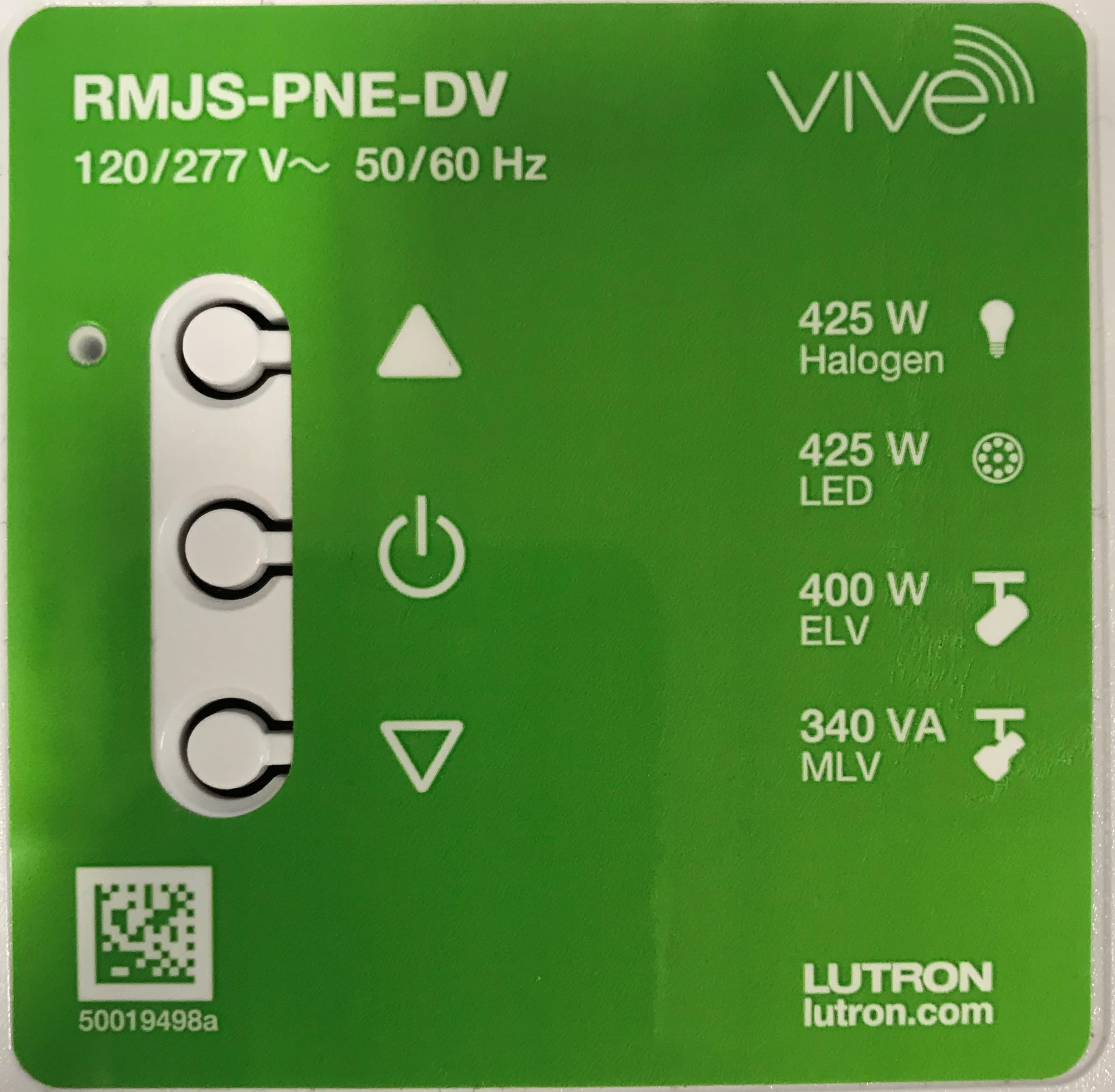
Click to zoom
Application Details
- Equipment Class
- DSR - Part 15 Remote Control/Security Device Transceiver
- Date of Grant
- Nov 18, 2020
- Application Purpose
- Original Equipment
- Date of Application
- Nov 18, 2020
- Equipment Note
- Lighting Control
- Frequency Range
- 431.50000000 - 436.60000000
- Country
- United States
Documents & Files
Document Text
Text extracted from the exhibit documents filed with the FCC. Open a document above to read the original.
Users Manual
Vive Installation Vi ve Phase Selectable Dimming Module Vive Emergency Phase Selectable Dimming Module Test Link Cal. + For each system, ensure that you have: One Dimming ModuleAt least one Wireless Transmitter Required Components Radio Powr Savr Occupancy / Vacancy Sensor (10 maximum) Radio Powr Savr Daylight Sensor (1 maximum) Pico Remote Control (10 maximum) Note: All drivers and ballasts used with Vive wireless controls must comply with the limits pursuant to CAN ICES-005 and the FCC rules. Dimming Module (1 maximum) lutron.com RMJS-PNE-DV 120 / 277 V~ 50 / 60 Hz 50019498a Raise Toggle Lower Indicator LED At least one phase dimmable lighting load (incandescent, halogen, LED, fluorescent, ELV, or ML V) Consult third-party fixtures installation guide for fixture-specific wiring. + Occupancy Sensors Daylight Sensor Wireless Controls Occupied: All lights 100%. Unoccupied: All lights off. Test Link Cal. All lights dim in response to daylight. OnAll lights 100% FavoriteAll lights 50% OffAll lights off Default Functionality 2 A Dimming Module must be installed in a metal 101.6 mm x 101.6 mm (4 in x 4 in) junction box (minimum depth 54 mm (2.125 in) with mounting screws (provided). Please consult local and national electric codes for proper installation. Lutron can provide a barrier, if required, to provide separation in the junction box between Class 1 and Class 2 wires. Note: if module cannot be fully seated into the junction box, try rotating the module 90, 180, or 270 degrees. Or move conduit hardware to a different knockout hole. If neither option works, an extension ring may be required. B Connect bare copper wire from junction box to green ground screw. C Once installed, energize the Dimming Module. D Use the Toggle button “ u” to toggle between high-end and OFF to verify ballasts or LED drivers wiring. E Use the Raise “ ▲ ” and Lower “ Δ ” buttons to verify control wiring. English All Wireless Transmitters must be installed within 9 m (30 ft) of the Dimming Module. 450 W Incandescent / Halogen 4 50 VA LED (reverse-phase) 3 A Lutron Hi-lume A-series LTE (13 drivers max) 200 W LED NEMA SSL 7A-2015 450 W ELV 400 VA MLV 400 VA Fluorescent 120 / 277 V~ 50 / 60 Hz RMJS-PNE-DV RMJS-PNE-DV-EM lutron.com RMJS-PNE-DV 120 / 277V~ 50 / 60 Hz 50019498a Radio Powr Savr Occupancy Sensor Pico Remote Control Dimming Module 9 m (30 ft) max 12 m (40 ft) 10 m (33 ft) Dimming Module Install in center of room to maximize RF coverage. A Connect mains wiring (switched hot, neutral, dimmed hot) to each fixture. 1 NEU HOT MAINS Fixture Earth Green / Yellow To additional fixtures Neutral Dimmed Line / Hot WARNING! Shock Hazard. May result in serious injury or death. Turn off power at circuit breaker before installing the unit. Sample ballast shown lutron.com RMJS-PNE-DV 120 / 277 V~ 50 / 60 Hz 50019498a Line / Hot (Black) Dimmed Line / Hot (Red) Neutral (White) To Fixtures Neutral Junction Box Important Notes: Please read before installing. For installation by a qualified electrician in accordance with all local and national electrical codes. •Note: Use copper conductors only. •Check to see that the device type and rating is suitable for the application. •DO NOT install if product has any visible damage. •If moisture or condensation is evident, allow the product to dry completely before installation. •Operate between 0 °C and 40 °C (32 °F and 104 °F) ambient. •0% to 90% humidity, non-condensing. •For indoor use only. •For spec submittal , see http://www.lutron.com/TechnicalDocumentLibrary/3691150.pdf •Operation of a low-voltage circuit with lamps inoperati ve or removed may result in transformer overheating and premature failure. Lutron strongly recommends the following: a. Do not operate low-voltage circuits without operative lamps in place. b. Replace burned-ou t lamps as quickly as possible. c. Use transformers that incorporate thermal protection or fused transformer primary windings to prevent t ransformer failure due to overcurrent. Lutron Electronics Co., Inc. 7200 Suter Road Coopersburg, PA 18036-1299 USA Start Here Programming with a Vive Hub 4 Mount, Wire, and Install Phase Dimmable Devices and Lighting Fixtures Consult third-party device installation guide Install Dimming Module Suggested Installation Location: Center of room to ensure proper RF coverage of area. For optimal RF performance: Module must not be fully enclosed in metal. No metal should exist anywhere within 200 mm (8 in) in front of the front plate of the module. Mount a minimum of 0.6 m (2 ft) away from the controlled fixture. Ensure the junction box is well grounded (preferably via a metal conduit between the controlled fixture and the module junction box). Note: For further information on set up, programming, and troubleshooting with a Vive system, please refer to the installation instructions included with the Vive hub or visit www.lutron.com/vive Note: For pr ogramming the Dimming Module without a Vive hub see reverse side. Customer Assistance www.lutron.com/support Troubleshootingwww.lutron.com/support Fixtures cannot be controlled locally from Dimming Module. •Ensure that the breaker(s) to the Dimming Module are energized. • • Ensure that the Dimming Module dimmed hot lead is wired to the lighting fixture(s). Dimming Module may be in emergency mode. Reset to factory defaults. Lights do not dim as expected. • Ensure that dimmed hot line is wired properly. • Dimming Module may be in emergency mode. Lights do not respond to Wireless Transmitter(s) (Pico remotes and RPS sensors). •Ensure that the br eaker(s) to the Dimming Module and any connected ballasts or LED drivers are energized. • Ensure that W ireless Transmitters are associated to the Dimming Module. Reset to factory defaults. Lights are unstable at low-end (or high-end) or flash/flicker at turn-on or turn-off. • Adjust low-end (or high-end) trim. Wireless Transmitter(s) cannot be associated to Dimming Module. •The maximum number of Wireless Transmitters have been associated…
Text truncated - open the document above for the full version.
Cover Letter(s)
Date: 02 Nov 2020 Federal Communications Commission 7435 Oakland Mills Road Columbia MD 21046 c.c. UL Verification Services Certification Division 47173 Benicia Street Fremont, CA 94538, USA To whom it may concern: I, the undersigned, hereby authorize UL LLC to act on our behalf in all manners relating to application for equipment authorization, including signing of all documents relating to these matters. Any and all acts carried out by UL LLC on our behalf shall have the same effect as acts of our own. I, the undersigned, hereby certify that we are not subject to a denial of federal benefits, that includes FCC benefits, pursuant to Section 5301 of the Anti-Drug Abuse Act of 1988, 21 U.S.C. 853(a). In authorizing UL LLC as our agent, we still recognize that we are responsible to: a) comply with the relevant provisions of the certification program; b) make all necessary arrangements for the conduct of the evaluation, including provision for examining documentation and access to all areas, records (including internal audit reports) and personnel for the purposes of evaluation (e.g. testing, inspection, assessment, surveillance, reassessment) and resolution of complaints; c) make claims regarding certification only in respect of the scope for which certification has been granted; d) do not use our product certification in such a manner as to bring the Certification Division into disrepute and not make any statement regarding our product certification which the Certification Division may consider misleading or unauthorized; e) upon suspension or cancellation of certification, discontinue use of all advertising matter that contains any reference thereto and return any certification documents as required by the Certification Division; f) use certification only to indicate the products are certified as being in conformity with specified standards; g) endeavor to ensure that no certificate or report nor any part thereof is used in a misleading manner; h) ensure that any reference to our product certification in communication media such as documents, brochures or advertising, complies with the requirements of the Certification Division; i) keep a record of all complaints made known to the us relating to the product’s compliance with requirements of the relevant standard and to make these records available to the Certification Division when requested; j) take appropriate action with respect to such complaints and any deficiencies found in products or services that affect compliance with the requirements for certification; k) document the actions taken. This authorization is valid until further written notice from the applicant. Sincerely Yours, Robert Spehalski Engineering Leader Lutron Electronics Co., Inc.
Cover Letter(s)
Federal Communications Commission 7435 Oakland Mills Road Columbia MD 21046 02 Nov 2020 Subject: Long Term Request for Confidentiality – JPZ0131 Dear Sir or Madam: This letter is to formally request long term confidentiality, per the FCC Rules 47 CFR 0.457 and 0.459, for materials or information submitted to the Commission to be withheld from public inspection. For all models in this submission, the following items are Lutron Electronics Co., Inc. confidential information that must be from public inspection by potential competitors to protect our business. 1. Schematic 2. Operation Description 3. Bill of Materials 4. Block Diagram Thank you for your cooperation. Sincerely, Robert Spehalski Engineering Leader Federal Communications Commission 7435 Oakland Mills Road Columbia MD 21046 02 Nov 2020 Subject: Short Term Request for Confidentiality – JPZ0131 Dear Sir or Madam: This letter is to formally request short term confidentiality, per the FCC Rules 47 CFR 0.457 and 0.459, for materials or information submitted to the Commission to be withheld from public inspection. For all models in this submission, Lutron Electronics Co., Inc. requests that materials or information submitted to the Commission be withheld from public inspection until 20 January 2021. 1. Internal Photos 2. External Photos 3. Test Setup Photos 4. User Manual Thank you for your cooperation. Sincerely, Robert Spehalski Engineering Leader
External Photos
FRONT BACK RMJS-PNE-DV PHOTOS TOP SIDE BOTTOM SIDE RIGHT SIDE LEFT SIDE
Internal Photos
VIEW OF FETS VIEW OF RESONANT LOOP BOTTOM OF PCB BOTTOM OF PCB WITH MOV LIFTED TOP OF PCB ALTERNATE SIDE VIEW OF ANTENNA BOARD SIDE VIEW OF ANTENNA BOARD
Test Report
NVLAP LAB CODE 200246-0 FCC CFR47 PART 15 SUBPART C ISED CANADA RSS-210 ISSUE 10 TEST REPORT FOR IN-WALL CONTROLLER MODEL NUMBER: PNE-DV FCC ID: JPZ0131 IC: 2851A-JPZ0131 REPORT NUMBER: R13488995-E1 ISSUE DATE: 2020-11-12 Prepared for LUTRON ELECTRONICS CO., INC. 7200 SUTER RD. COOPERSBURG PA, 18036, USA Prepared by UL LLC 12 LABORATORY DR. RESEARCH TRIANGLE PARK, NC 27709 USA TEL: (919) 549-1400 REPORT NO: R13488995-E1 DATE: 2020-11-12 FCC ID: JPZ0131 IC: 2851A-JPZ0131 Page 2 of 38 UL LLC FORM NO: 03-EM-F00858 12 Laboratory Dr., RTP, NC 27709 TEL: (919) 549-1400 This report shall not be reproduced except in full, without the written approval of UL LLC. Revision History Rev. Issue Date Revisions Revised By 1 11/04/20 Initial Issue Mike Antola 2 11/12/20 Misc. editorial updates Mike Antola REPORT NO: R13488995-E1 DATE: 2020-11-12 FCC ID: JPZ0131 IC: 2851A-JPZ0131 Page 3 of 38 UL LLC FORM NO: 03-EM-F00858 12 Laboratory Dr., RTP, NC 27709 TEL: (919) 549-1400 This report shall not be reproduced except in full, without the written approval of UL LLC. TABLE OF CONTENTS 1. ATTESTATION OF TEST RESULTS ..................................................................................4 2. TEST METHODOLOGY ......................................................................................................5 3. FACILITIES AND ACCREDITATION ..................................................................................5 4. DECISION RULES AND MEASUREMENT UNCERTAINTY ...............................................5 4.1. METROLOGICAL TRACEABILITY ...............................................................................5 4.2. DECISION RULES ........................................................................................................5 4.3. MEASUREMENT UNCERTAINTY ................................................................................6 4.4. SAMPLE CALCULATION .............................................................................................6 5. EQUIPMENT UNDER TEST ................................................................................................7 5.1. DESCRIPTION OF EUT ...............................................................................................7 5.2. DESCRIPTION OF AVAILABLE ANTENNAS ...............................................................7 5.3. SOFTWARE AND FIRMWARE .....................................................................................7 5.4. WORST-CASE CONFIGURATION AND MODE ...........................................................7 5.5. MODIFICATIONS .........................................................................................................7 5.6. DESCRIPTION OF TEST SETUP .................................................................................8 6. TEST AND MEASUREMENT EQUIPMENT ........................................................................9 7. ANTENNA PORT TEST RESULTS ...................................................................................11 7.1. 20 dB AND 99% BW ...................................................................................................11 7.2. DUTY CYCLE .............................................................................................................15 7.3. TRANSMISSION TIME ...............................................................................................17 8. RADIATED EMISSION TEST RESULTS...........................................................................18 8.1. TX RADIATED SPURIOUS EMISSION ......................................................................18 9. AC MAINS LINE CONDUCTED EMISSIONS ....................................................................34 10. SETUP PHOTOS ...........................................................................................................38 REPORT NO: R13488995-E1 DATE: 2020-11-12 FCC ID: JPZ0131 IC: 2851A-JPZ0131 Page 4 of 38 UL LLC FORM NO: 03-EM-F00858 12 Laboratory Dr., RTP, NC 27709 TEL: (919) 549-1400 This report shall not be reproduced except in full, without the written approval of UL LLC. 1. ATTESTATION OF TEST RESULTS COMPANY NAME: Lutron Electronics Co., Inc. 7200 Suter Rd. Coopersburg, PA, 18036, USA EUT DESCRIPTION: In-Wall Controller MODEL: PNE-DV SERIAL NUMBER: 02EFF09E / 02EFF0A1 SAMPLE RECEIVE DATE: 2020-10-26 DATE TESTED: 2020-10-26 to 2020-10-28 APPLICABLE STANDARDS STANDARD TEST RESULTS FCC PART 15 SUBPART C Complies ISED CANADA RSS-210 Issue 10, Annex A Complies ISED CANADA RSS-GEN Issue 5 Complies UL LLC tested the above equipment in accordance with the requirements set forth in the above standards. The test results show that the equipment tested is capable of demonstrating compliance with the requirements as documented in this report. The results documented in this report apply only to the tested sample, under the conditions and modes of operation as described herein. It is the manufacturer's responsibility to assure that additional production units of this model are manufactured with identical electrical and mechanical components. All samples tested were in good operating condition throughout the entire test program. Measurement Uncertainties are published for informational purposes only and were not taken into account unless noted otherwise. This document may not be altered or revised in any way unless done so by UL LLC and all revisions are duly noted in the revisions section. Any alteration of this document not carried out by UL LLC will constitute fraud and shall nullify the document. This report must not be used by the client to claim product certification, approval, or endorsement by NVLAP, NIST, or any agency of the U.S. government. Approved & Released For UL LLC By: Prepared By: Bob DeLisi Mike Antola Principal Engineer Staff Engineer CONSUMER TECHNOLOGY DIVISION CONSUMER TECHNOLOGY DIVISION UL LLC UL LLC REPORT NO: R13488995-E1 DATE: 2020-11-12 FCC ID: JPZ0131 IC: 2851A-JPZ0131 Page 5 of 38 UL LLC FORM NO: 03-EM-F0085…
Text truncated - open the document above for the full version.
Test Setup Photos
N VLAP Lab code: 200246-0 PHOTOS EXHIBIT Report Number. : R13488995-EP1 Applicant : Lutron Electronics Co Inc. 7200 Suter Rd. Coopersburg, PA, 18036-1249, USA Model : PNE-DV FCC ID : JPZ0131 IC : 2851A-JPZ0131 EUT Description : In-Wall Controller Test Standard(s) : FCC 47 CFR PART 15 SUBPART C ISED RSS -210 ISSUE 10 Date Of Issue: November 12, 2020 Prepared by: UL LLC 12 Laboratory Dr. Research Triangle Park, NC 27709 U.S.A. TEL: (919) 549-1400 REPORT NO: R13488995-EP1 DATE: 11/12/2020 FCC ID: JPZ0131 IC: 2851A-JPZ0131 Page 2 of 9 UL LLC 12 Laboratory Dr., RTP, NC 27709, USA TEL:(919) 549-1400 This report shall not be reproduced except in full, without the written approval of UL LLC. REPORT REVISION HISTORY Re v. Issue Da te Revisions Revised By 1 11/4/2020 Initial Issue M ike Antola 2 11/12/2020 Misc. editorial updates Mike Antola REPORT NO: R13488995-EP1 DATE: 11/12/2020 FCC ID: JPZ0131 IC: 2851A-JPZ0131 Page 3 of 9 UL LLC 12 Laboratory Dr., RTP, NC 27709, USA TEL:(919) 549-1400 This report shall not be reproduced except in full, without the written approval of UL LLC. R EPORT REVISION HISTORY ..................................................................................................2 1.SETUP PHOTOS .................................................................................................................4 REPORT NO: R13488995-EP1 DATE: 11/12/2020 FCC ID: JPZ0131 IC: 2851A-JPZ0131 Page 4 of 9 UL LLC 12 Laboratory Dr., RTP, NC 27709, USA TEL:(919) 549-1400 This report shall not be reproduced except in full, without the written approval of UL LLC. 1.SETUP PHOTOS CONDUCTED RF MEASUREMENT SETUP BENCHTOP PHOTO REPORT NO: R13488995-EP1 DATE: 11/12/2020 FCC ID: JPZ0131 IC: 2851A-JPZ0131 Page 5 of 9 UL LLC 12 Laboratory Dr., RTP, NC 27709, USA TEL:(919) 549-1400 This report shall not be reproduced except in full, without the written approval of UL LLC. RADIATED RF MEASUREMENT SETUP RADIATED PHOTO (BELOW 30MHz) REPORT NO: R13488995-EP1 DATE: 11/12/2020 FCC ID: JPZ0131 IC: 2851A-JPZ0131 Page 6 of 9 UL LLC 12 Laboratory Dr., RTP, NC 27709, USA TEL:(919) 549-1400 This report shall not be reproduced except in full, without the written approval of UL LLC. RADIATED PHOTO (30-1 000MHz) REPORT NO: R13488995-EP1 DATE: 11/12/2020 FCC ID: JPZ0131 IC: 2851A-JPZ0131 Page 7 of 9 UL LLC 12 Laboratory Dr., RTP, NC 27709, USA TEL:(919) 549-1400 This report shall not be reproduced except in full, without the written approval of UL LLC. RADIATED PHOTO (ABOVE 1GHz) REPORT NO: R13488995-EP1 DATE: 11/12/2020 FCC ID: JPZ0131 IC: 2851A-JPZ0131 Page 8 of 9 UL LLC 12 Laboratory Dr., RTP, NC 27709, USA TEL:(919) 549-1400 This report shall not be reproduced except in full, without the written approval of UL LLC. AC LINE CONDUCTED SETUP AC LINE CONDUCTED PHOTO REPORT NO: R13488995-EP1 DATE: 11/12/2020 FCC ID: JPZ0131 IC: 2851A-JPZ0131 Page 9 of 9 UL LLC 12 Laboratory Dr., RTP, NC 27709, USA TEL:(919) 549-1400 This report shall not be reproduced except in full, without the written approval of UL LLC. E ND OF PHOTOS EXHIBIT
Contact Information
Applicant
Daniel Schlegel(Standards Compliance Supervisor)
Technical Contact
UL LLCLariah Ijames
[email protected]919-549-0945
12 Laboratory Drive · RTP, North Carolina · United States
Test Firm
UL LLCRick Titus
Technical Specifications
| # | Rule Parts | Frequency Range | Power Output |
|---|---|---|---|
| 1 | 15.231 | 431.5 MHz - 436.6 MHz | - |
Other Applications from Lutron Electronics Company Inc
JPZ0161
Sep 03, 2026Wireless Interface
Equipment Class
DTS - Digital Transmission SystemJPZ0159
Aug 12, 2026Wireless Processor
Equipment Class
DTS - Digital Transmission SystemJPZ0158
Jul 27, 2026Copy of Wireless Processor
Equipment Class
DTS - Digital Transmission SystemJPZ0157
Mar 26, 2026LED Downlight
Equipment Class
DTS - Digital Transmission SystemJPZ0155
Sep 30, 2024LED Lighting Controller
Equipment Class
DTS - Digital Transmission System