JPZ0139Smart Dimmer
Lutron Electronics Company Inc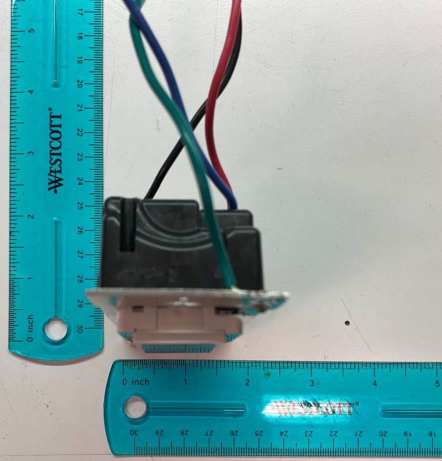
Click to zoom
Application Details
- Equipment Class
- DSR - Part 15 Remote Control/Security Device Transceiver
- Date of Grant
- Mar 23, 2022
- Application Purpose
- Original Equipment
- Date of Application
- Mar 23, 2022
- Equipment Note
- Smart Dimmer
- Frequency Range
- 431.50000000 - 437.60000000
- Country
- United States
Documents & Files
Document Text
Text extracted from the exhibit documents filed with the FCC. Open a document above to read the original.
Users Manual
ON OFF ON OFF ON OFF ON OFF x3 x2 Hold for 6 seconds until LEDs start blinking quick-start guide In-wall dimmer Welcome—and thank you for purchasing a Caséta Wireless in-wall dimmer. In order to control your lights from an app or remote, you’ll need to replace an existing switch with a Caséta Wireless in-wall dimmer. Before you install the dimmer, please watch the installation video at www.casetawireless.com/support We hope you enjoy the convenience of Caséta Wireless! NOTE: You can mix and match dimmable LED and CFLs, as well as halogen and incandescent light bulbs, with Caséta Wireless dimmers. Dimmable LED and CFL light bulbs vary in their dimming performance. If you’re using these bulbs and they flicker or turn off, please visit www.casetawireless.com/lowend for information on adjusting the dimmer for best bulb performance. For a complete list of compatible dimmable LEDs and CFLs, please visit www.casetawireless.com/bulblist Compatible light bulbs include: Cree ® BA19-08027OMF-12DE26-1U100 CR6-575L EcoSmart ® ECS BR30 W27 FL 120 ECS 20 WW FL 50WE 120 Feit ® A19/OM/LED Philips® 9290002295 Sylvania ® LED12A19/DIM/O/827 LED21PAR38/DIM/P/930/FL30 LED—up to 150 W CFL—up to 150 W Contents supplied Double your warranty In-wall dimmer (DS-6WCL) Tools you’ll need Works with energy efficient dimmable light bulbs: Flat-head screwdriver Wire connectors (3) Phillips-head screwdriver Pliers Screws (2) Installation for lights with one wall switch (single pole) Installing your dimmer Using your Caséta Wireless kit (sold separately) Some lights have one wall switch, while others have two or more wall switches (such as stair lights, which have a switch at both the top and bottom of the stairs). We’ve included instructions for lights with one wall switch (called a single pole). If your light has more than one switch (called a 3-way), please visit www.casetawireless.com/3way for complete installation instructions and how-to videos. WARNING: SHOCK HAZARD May result in serious injury or death. Turn off power at circuit breaker or fuse before installing. 1 Turn power off at circuit breaker! 1 Press and hold “off” button on dimmer 2 Press and hold “off” button on remote 4 Connect the dimmer 5 Mount the dimmer 6 Attach the wallplate 7 Turn power on at circuit breaker 2 Remove existing switch from wall Remove the wallplate from switch. 3 Remove side sections (if necessary) Remove the switch and pull it away from the wall. * If your switch has more than 3 wires attached, see “Installing Caséta Wireless in a 3-way switch application” video at www.casetawireless.com/3way Bend back and forth. 3 5 1 2 3 1 4 6 Ground Ground Ground 7 2 Disconnect all three wires* from the switch. 1 Connect the bar e copper (or green) “ground” wire from the wallbox to the green wire on the dimmer using a wire connector. 2 Connect either of the r emaining wires from the wallbox to either of the remaining wires on the dimmer using a second wire connector. 3 Connect the r emaining wire from the wall to the remaining wire on the dimmer using a third wire connector. Do not remove outside side sections on dimmers at the end of gang. Each dimmer has inside side sections removed. Dimmer at middle has all side sections removed. Attach the adapter to the dimmer using the screws provided and snap on the wallplate. ‘snap’ (If you installed the dimmer next to other dimmers or switches, you’ll need to install a wallplate with the correct size/number of openings to accommodate all the devices.) Use the screws provided. Pairing the dimmer and Pico remote control Go to www.casetawirless.com/support for additional troubleshooting suggestions. SymptomsProbable cause and action Light does not turn on or in-wall dimmer LEDs do not light up. • Light bulb(s) burned out. • Breaker is OFF or tripped. • Light not properly installed. • Wiring error. • FASS switch on the dimmer is in the Off position. Light does not respond to Pico remote control. • The dimmer failed to pair with Pico remote control; see Pairing the dimmer and Pico remote control. • The dimmer is already at the light level the Pico remote control is sending. • The Pico remote control is outside the 30 ft (9 m) operating range. • The Pico remote control battery is low. • The Pico remote control battery is installed incorrectly. • Bulbs turn off while being dimmed. • Bulbs turn on at high light level but do not turn on at a low light level. • Bulbs flicker or flash when dimmed to a low light level. Verify bulbs are marked dimmable and visit www.casetawireless.com/ lowend for information on adjusting the dimmer for best bulb performance. Love Caséta W ireless dimmers? Have ideas for making them better? Tell us what you think and we’ll extend your warranty by 1 year. www.casetawireless.com/register For advanced features, tips for using Caséta TM Wireless dimmers with CFLs and LEDs, the complete CasétaTM Wireless product line, and more, please visit www.casetawireless.com/features Changing the favorite light level on the Pico remote control (sold separately) You can use the round “favorite” button on the Pico remote control to recall a favorite light level. We’ve set it to 50%, but you can change it to any level you like. Favorite Replacing light bulbs using FASS Pull the FASS switch out on the in-wall dimmer to remove power at the light socket. CAUTION Use only with permanently installed fixtures with dimmable LED, dimmable CFL, halogen, or incandescent,lamps. To avoid overheating and possible damage to other equipment, do not use to control receptacles, motor-driven appliances, or transformer-supplied appliances. Codes Install in accordance with all national and local electrical codes. Grounding When no “grounding means” exist in wallbox, the National Electrical Code (NEC®) allows a control to be installed as a replacement if 1) a nonmetallic, noncombustible faceplate is used with nonmetallic attachment screws or 2) the circuit is protected by a ground fault circuit interrupter (GFCI). When instal…
Text truncated - open the document above for the full version.
Cover Letter(s)
LUTRON ELECTRONICS CO., INC. Label and Label Placement Exhibit Change Request for JPZ0139 Date: 5-May-2022 To: Federal Communications Commission 7435 Oakland Mills Road Columbia MD 21046 This cover letter is to confirm the following: We acknowledge that the previously provided EUT label as well as the EUT label placement exhibits have already been made public for JPZ0139. Due to the sensitive information contained on the exhibits, and to minimize additional public exposure, updated versions have been provided for replacement. Applicant Company N ame: Lutron Electronics Co., Inc. Address: 7200 Suter Rd. Coopersburg, PA 18036 U.S.A. Telephone No.: 610-282-3800 Fax N o.: 610-282-7611 Email: [email protected] Certification/Registration Number: FCC ID: JPZ0139 Standards Compliance Supervisor Lutron Electronics Co., Inc. 7200 SUTER ROAD COOPERSBURG, PA 18036-1299 lEL.EPH0NE 610 282-3800 FAX 610 282-3769
External Photos
Lutron Electronics Co., Inc. Confidential 03/16/2022 Lutron DS-6WCL External Photos Front View Lutron Electronics Co., Inc. Confidential 03/16/2022 Back View Lutron Electronics Co., Inc. Confidential 03/16/2022 Top View Lutron Electronics Co., Inc. Confidential 03/16/2022 Bottom View Lutron Electronics Co., Inc. Confidential 03/16/2022 Right Side View Lutron Electronics Co., Inc. Confidential 03/16/2022 Left Side View
ID Label/Location Info
�FLEXCON SECTION 1 - SIZE SIZE OF LABEL: Width: 0.7 3 in Lengrth: 2 . 33 in PRODUCT INFORMATIO THE.R lLfihn SELECT ® 21940 Product Description: THERMLfilm SELECT 21940 is a UL-recognized/CSA-accepted, 2.0 mil gloss topcoated thermal transfer printable, white polye ter coated with an aggressive, permanent acrylic adhesive, and backed with a roll fom1 rel ease liner. • THERMLfi.lm PM 200 \l, ..................................................... 2.0 mil gloss white polyester desi gn ed for high-performru1ce label applications.
ID Label/Location Info
Label Placement
Internal Photos
Lutron Electronics Co., Inc. Confidential 03/16/2022 Lutron DS-6WCL Internal Photos Top PCB Lutron Electronics Co., Inc. Confidential 03/16/2022 Top PCB (antenna location) Lutron Electronics Co., Inc. Confidential 03/16/2022 Bottom PCB with Backcover Lutron Electronics Co., Inc. Confidential 03/16/2022 Bottom PCB
RF Exposure Info
B B E E C C I I N N C C O O R R P P O O R R A A T T E E D D MAXIMUM PERMISSABLE EXPOSURE (MPE) REPORT TEST STANDARDS: U.S. Title 47 Chapter 1 Subchapter A Part 2 Subpart J Lutron Model DS-6WCL FCC ID: JPZ0139 REPORT# BEC-2185-02 CUSTOMER: Lutron Electronics Company Incorporated 7200 Suter Road Coopersburg, PA 18036 PREPARED BY: Paul Banker, Test Engineer REVIEWED and APPROVED BY: Steve Fanella, Quality Manager The results described in this report relate only to the item(s) tested. This document shall not be reproduced except in full without prior written permission of BEC Incorporated Report # BEC-2185-02 Lutron Model DS-6WCL MPE Test Report Release Date: 02/21/2022 Page 2 of 7 TABLE OF CONTENTS Notice To Customer ...................................................................................................................... 3 Revision History ............................................................................................................................ 3 1.0 Administrative Information .............................................................................................. 4 1.1 General Information Table ............................................................................................... 4 1.2 Maximum Permissible Exposure Calculation .................................................................. 5 1.3 Maximum Permissible Exposure (MPE) 01/27/2022 ...................................................... 7 Report # BEC-2185-02 Lutron Model DS-6WCL MPE Test Report Release Date: 02/21/2022 Page 3 of 7 Notice To Customer This report and any recommendations it contains represent the result of BEC’s testing and assessment on behalf of your company. Testing has been conducted according to accepted engineering standards and practices. This report reflects testing and assessment of product samples provided by your company and may not reflect the characteristics of other samples, especially those produced at different times. Therefore this report and its findings and recommendations, if implemented, should not be construed as an assurance or implied warranty for the continuing electromagnetic compatibility (EMC) of the product. BEC shall not be liable for incidental or consequential damages, even if advised of the possibility thereof. BEC will not disseminate this report to other parties without your express permission. You may reproduce this report in its entirety including this notice and the entireties of any supplemental test reports on the same product (e.g. reports on additional testing following modification). However ‘you may not reproduce portions of the report (except for the entirety of the summary section) or quote from it for any purpose without specific prior written permission from BEC’. Revision History Revision # Description of Changes Date of Changes Date Released 0 Test Report Initial Release N/A 02/21/2022 Report # BEC-2185-02 Lutron Model DS-6WCL MPE Test Report Release Date: 02/21/2022 Page 4 of 7 1.0 Administrative Information 1.1 General Information Table Project Number BEC-2185 Manufacturer Lutron Electronics Model Number Tested DS-6WCL EUT Sample Type FCC Test Code Radiated Sample EUT Serial Number 030A55C1 EUT Sample Number 2185-01 EUT Firmware Version 2.01 Frequency of Operation 431 MHz to 437 MHz Antenna Gain -14.85 dBi Antenna Type Loop Modulation FSK FCC Classification DSR, Part 15 Remote Control/Security Device Transceiver Date Samples Received 01/26/2022 Sample Type and Condition Received Production Unit Suitable for Test EUT Description Vogelkop Wireless RF Dimmer FCC ID JPZ0139 Applicable FCC Rules 47 CFR Part 2.1091, OET Bulletin 65 Report # BEC-2185-02 Lutron Model DS-6WCL MPE Test Report Release Date: 02/21/2022 Page 5 of 7 1.2 Maximum Permissible Exposure Calculation §1.1307 Actions that may have a significant environmental effect, for which Environmental Assessments (EAs) must be prepared. (b)(1) Requirements. (i) With respect to the limits on human exposure to RF provided in §1.1310 of this chapter, applicants to the Commission for the grant or modification of construction permits, licenses or renewals thereof, temporary authorities, equipment authorizations, or any other authorizations for radiofrequency sources must either: (A) Determine that they qualify for an exemption pursuant to §1.1307(b)(3); (B) Prepare an evaluation of the human exposure to RF radiation pursuant to §1.1310 and include in the application a statement confirming compliance with the limits in §1.1310; or (C) Prepare an Environmental Assessment if those RF sources would cause human exposure to levels of RF radiation in excess of the limits in §1.1310 §1.1310 Radiofrequency radiation exposure limits. (2) At operating frequencies less than or equal to 6 GHz, the limits for maximum permissible exposure (MPE), derived from whole-body Specific Absorption Rate (SAR) limits and listed in Table 1 of paragraph (e) of this section, may be used instead of whole-body SAR limits as set forth in paragraph (a) through (c) of this section to evaluate the environmental impact of human exposure to RF radiation as specified in §1.1307(b), except for portable devices as defined in §2.1093 as these evaluations shall be performed according to the SAR provisions in §2.1093 of this chapter. (4) Both the MPE limits listed in Table 1 of paragraph (e) of this section and the SAR limits as set forth in paragraph (a) through (c) of this section and in §2.1093 of this chapter are for continuous exposure, that is, for indefinite time periods. Exposure levels higher than the limits are permitted for shorter exposure times, as long as the average exposure over the specified averaging time in Table 1 is less than the limits. Detailed information on our policies regarding procedures for evaluating compliance with all of these exposure limits can be found in the FCC's OET Bulletin 65, “Evaluating Compliance with FCC Guidelines for Human Exposure to Radiofrequency Electromagnetic Field…
Text truncated - open the document above for the full version.
Test Report
B B E E C C I I N N C C O O R R P P O O R R A A T T E E D D CERTIFICATION APPLICATION TEST REPORT TEST STANDARDS: FCC Part 15 Subpart C Section 15.231 RSS-Gen/RSS-210 Annex A Intentional Radiator Lutron Model DS-6WCL Vogelkop RF Wireless Dimmer REPORT BEC-2185-01 REV1 TEST DATES: 01/27/2022 – 02/10/2022 CUSTOMER: Lutron Electronics Company Incorporated 7200 Suter Road Coopersburg, PA 18036 PREPARED BY: Paul Banker, Test Engineer REVIEWED and APPROVED BY: Steve Fanella, Quality Manager The results described in this report relate only to the item(s) tested. This document shall not be reproduced except in full without prior written permission of BEC Incorporated Report # BEC-2185-01 REV1 Lutron Model DS-6WCL FCC Part 15.231 RSS-210 Test Report Release Date: 02/16/2022 Page 2 of 38 TABLE OF CONTENTS Notice to Customer ....................................................................................................................... 4 Revision History ............................................................................................................................ 4 1.0 Administrative Information .............................................................................................. 5 1.1 General Project Details..................................................................................................... 5 1.2 Preface .............................................................................................................................. 5 1.3 Laboratory and Customer Information ............................................................................. 6 1.4 Measurement Uncertainty ................................................................................................ 7 1.5 Test Result Summary Table ............................................................................................. 8 1.6 Condition of Received Sample ......................................................................................... 9 1.7 Climatic Environment ...................................................................................................... 9 1.8 Test Equipment ................................................................................................................ 9 2.0 Equipment Under Test .................................................................................................... 10 2.1 EUT Description ............................................................................................................ 10 2.2 Product Category Standards ........................................................................................... 10 2.3 Product Classification .................................................................................................... 10 2.4 Test Configuration.......................................................................................................... 10 2.5 Test Configuration Rationale ......................................................................................... 11 2.6 Test Setup Configuration Block Diagram ...................................................................... 11 2.7 EUT Information, Interconnection Cabling and Support Equipment ............................ 12 2.8 Test Signals and Test Modulation .................................................................................. 12 2.9 Grounding....................................................................................................................... 12 2.10 EUT Power ................................................................................................................. 12 2.11 EUT Modifications ..................................................................................................... 12 3.0 Applicable Requirements, Methods, and Procedures .................................................. 13 3.1 Applicable Requirements ............................................................................................... 13 3.1.1 FCC and ISED Requirements ..................................................................................... 13 3.1.2 Basic Test Methods and Test Procedures ................................................................... 13 3.2 Deviations or Exclusions from the Requirements .......................................................... 13 4.0 Test Results ....................................................................................................................... 14 4.1 Antenna Requirement (47 CFR 15.203) (RSS-Gen, 6.2) ............................................... 14 4.2 Antenna Construction (47 CFR 15.203) (RSS-Gen, 6.2) ............................................... 14 4.3 Radiated Emissions (47 CFR 15.209 and 15.231 (b) and 15.35(b)) (RSS-210 A.1.2) .. 14 4.3.1 Radiated Emissions Test Facility ............................................................................... 15 4.3.2 Restricted and Non-restricted Bands Radiated Emissions Test Procedure ................ 16 4.3.3 Radiated Emissions General Test Information ........................................................... 17 4.3.4 Radiated Emissions 9 kHz – 30 MHz Test Results (02/01/2022) .............................. 17 4.3.5 Radiated Emissions 30 – 6000 MHz Test Results (01/27/2022 to 01/31/2022) ........ 18 4.3.5.1 Field Strength of Fundamental Emissions (01/27/2022) ........................................ 18 4.3.5.2 Field Strength of Spurious Emissions, 2 nd Harmonic (01/28/2022 and 01/31/2022) 19 4.3.5.3 Spurious Radiated Emissions 1 – 5 GHz Test Results (01/31/2022) ..................... 20 4.4 Duty Cycle Measurement (ANSI C63.10) ..................................................................... 21 4.4.1 Duty Cycle Measurement – Test Procedure ............................................................... 21 4.4.2 Duty Cycle Measurement General Test Information ................................................. 21 4.4.3 Duty Cycle Measurement Test Results (01/27/2022) .....…
Text truncated - open the document above for the full version.
Test Setup Photos
Test Setup Pictures for Lutron Model DS-6WCL Vogelkop RF Wireless Dimmer FCC ID: JPZ0319 IC ID: 2851A-JPZ0319 Conducted Emissions AC Mains Test Setup Picture Radiated Emissions Test Setup Pictures Radiated Emissions 9 kHz to 30 MHz Radiated Emissions Test Setup Pictures Radiated Emissions 30 Hz to 1000 MHz Radiated Emissions 1 GHz to 6 GHz Bench Testing Setup Picture
Contact Information
Applicant
Daniel Schlegel(Standards Compliance Supervisor)
Test Firm
BEC IncorporatedSteve Fanella
Technical Specifications
| # | Rule Parts | Frequency Range | Power Output |
|---|---|---|---|
| 1 | 15.231 | 431.5 MHz - 437.6 MHz | - |
Other Applications from Lutron Electronics Company Inc
JPZ0161
Sep 03, 2026Wireless Interface
Equipment Class
DTS - Digital Transmission SystemJPZ0159
Aug 12, 2026Wireless Processor
Equipment Class
DTS - Digital Transmission SystemJPZ0158
Jul 27, 2026Copy of Wireless Processor
Equipment Class
DTS - Digital Transmission SystemJPZ0157
Mar 26, 2026LED Downlight
Equipment Class
DTS - Digital Transmission SystemJPZ0155
Sep 30, 2024LED Lighting Controller
Equipment Class
DTS - Digital Transmission System