JPZ0154Fan Wall Control
Lutron Electronics Company Inc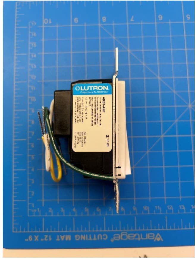
Click to zoom
Application Details
- Equipment Class
- DTS - Digital Transmission System
- Date of Grant
- May 14, 2024
- Application Purpose
- Original Equipment
- Date of Application
- May 14, 2024
- Equipment Note
- Fan Wall Control
- Frequency Range
- 2412.00000000 - 2462.00000000
- Country
- United States
Documents & Files
Document Text
Text extracted from the exhibit documents filed with the FCC. Open a document above to read the original.
Users Manual
Commande de ventilateur HomeWorks Ventilateurs en CA seulement HRST-ANF 120 V~ 50 / 60 Hz 1,5 A Aide www.lutron.com/HWsupport INFORMATIONS FCC / IC Cet appareil est conforme à la partie 15 des règles du FCC et aux normes industrielles RSS d’exemption de licence du Canada. Le fonctionnement est sous réserve des deux conditions suivantes : (1) Cet appareil ne doit pas provoquer d’interférence, et (2) Cet appar eil doit accepter toutes les interférences, y compris les interférences qui pourraient provoquer un fonctionnement indésirable. Les modifications qui n’ont pas été expressément approuvées par Lutron Electronics Co., Inc. peuvent annuler le pouvoir de l’utilisateur d’utiliser cet équipement. REMARQUE : Cet équipement a été testé et est conforme aux limites d’un appareil numérique de Classe B en vertu de la partie 15 des règles de la FCC. Ces limites sont conçues pour fournir une protection raisonnable face aux interférences nuisibles dans une installation résidentielle. Cet équipement génère, utilise et peut émettre une énergie de fréquence radio et, s’il n’est pas installé et utilisé conformément aux instructions, il peut provoquer des interférences nuisibles aux communications radio. Cependant, il n’y a aucune garantie que des interférences ne surviendront dans une installation particulière. Si cet équipement provoque des interférences nuisibles pour la réception radio et télévisuelle, ce qui peut être déterminé en allumant et en éteignant l’équipement, il est recommandé que l’utilisateur tente de corriger ces interférences en utilisant une ou plusieurs des mesures suivantes : • Réorientez ou r epositionnez l’antenne réceptrice • Augmentez la séparation entr e l’équipement et le récepteur • Connectez l’équipement à une prise électrique se tr ouvant sur un circuit différent de celui où le récepteur est connecté • Demandez l’aide du vendeur ou d’un technicien radio/TV expérimenté Cet équipement est conforme aux limites d’exposition aux rayonnements FCC / ISED établies pour un envir onnement non contrôlé. L’utilisateur doit éviter une exposition prolongée à moins de 20 cm (7,9 po) de l’antenne, ce qui peut dépasser les limites d’exposition aux fréquences radio FCC / ISED. Cet appareil numérique de classe B est conforme à la norme ICES-003 du Canada. Lutron, le logo Lutron, FASS, HomeWorks et Sunnata sont des marques commerciales ou déposées de Lutron Electronics Co., Inc. aux États- Unis et/ou dans d’autres pays. Tous les autres noms de produits, logos et marques appartiennent à leurs propriétaires respectifs. © 2024 Lutr on Electronics Co., Inc. ON OFF ON OFF Installer votre commande de ventilateur AVERTISSEMENT : RISQUE D’ÉLECTROCUTION. Peut causer des blessures graves ou la mort. Coupez l’alimentation au niveau du disjoncteur ou du fusible avant l’installation. 1 Régler la vitesse du ventilateur 2 Couper l’alimentation au niveau du disjoncteur ! 3 Retirer l’interrupteur existant du mur Retirez la plaque murale de l’interrupteur. Réglez le ventilateur à la vitesse la plus élevée à l’aide de la chaînette de commande. Tirez l’interrupteur du mur. Placez l’étiquette sur le fil du ventilateur. 4 Raccorder la commande du ventilateur 1 Raccordez le fil de cuivre dénudé (ou vert) « masse » du boîtier d’encastrement au fil vert de la commande du ventilateur à l’aide d’un connecteur de fils. 2 Enroulez le fil de ligne/sous tension autour de la borne à vis et serrez fermement. Référence de couple : 0,55 N•m (5 po-lb). 3 Raccor dez les fils neutres du boîtier d’encastrement au fil blanc de la commande de ventilateur à l’aide d’un connecteur de fils. 4 Raccor dez le fil du ventilateur/étiqueté du boîtier d’encastrement au fil jaune de la commande de ventilateur à l’aide d’un connecteur de fils. 5 Montez la commande du ventilateur sur le mur . 6 Remettez l’appar eil sous tension. Fonctionnement F A S S • F A S S • F A S S • F A S S • F A S S • F A S S • On Off SymptômesCause probable et action Le ventilateur ne s’ALLUME pas et aucun indicateur lumineux ne s’ALLUME. • Assurez-vous que la chaînette de commande du ventilateur est réglée sur le réglage le plus haut possible. • Les fils du ventilateur et de ligne peuvent être inversés. Intervertissez les fils reliés au fil jaune et à la borne à vis noire de la commande du ventilateur. Reportez-vous au schéma de câblage à l’Étape 4. • Le fil neutre n’est pas raccordé. Reportez-vous au schéma de câblage à l’Étape 4. • L ’interrupteur de service accessible à l’avant (FASS) est en position ARRÊT. Actionnez l’interrupteur FASS en position MARCHE. • Le disjoncteur est ouvert ou déclenché (ou un fusible a grillé). Réinitialisez le disjoncteur ou remplacez le fusible. Si la condition persiste, contactez l’assistance à la clientèle de Lutr on ou un électricien qualifié. Le ventilateur ne s’ALLUME pas et les indicateurs lumineux s’ALLUMENT. Le commutateur de direction du ventilateur est réglé entre la position avant et arrière. Réglez le commutateur dans la position souhaitée. La vitesse du ventilateur est trop basse.Réglez la vitesse de la chaînette de commande du ventilateur en position haute. Seule la vitesse élevée semble fonctionner. Les commandes de ventilateur Sunnata sont conçues pour fonctionner uniquement avec les ventilateurs en CA. Confirmez auprès du fabricant du ventilateur. Dépannage REMARQUES IMPORTANTES 1. Utilisation à l’intérieur seulement. 2. Fonctionne entre 0 °C (32 °F) et 40 °C (104 °F). 3. Utilisez ce modèle pour commander un ventilateur de plafond à pales. 4. Utilisez la chaînette de commande du ventilateur pour le régler à sa vitesse maximale. 5. Ne l’utilisez pas pour commander des ventilateurs à commandes de vitesse intégr ées autres qu’une chaînette de commande (c.à.d. les ventilateurs ayant une télécommande ou Wi-Fi), à moins que cette commande intégrée soit retirée du ventilateur de plafond. 6. Ne le connectez à aucun autr e appareil motorisé ou à aucun autre type de charge d’éclairage. 7. Ne l’utilisez pas pour contrôler les char…
Text truncated - open the document above for the full version.
Users Manual
Fan Control P/N 043595 Rev. A AC fan only Please read before installing HomeWorks Fan Control HRST-ANF , 120 V ~ 50 / 60 Hz 1.5 A English Help www.lutron.com/support This device complies with part 15 of the FCC Rules and Industry Canada license-exempt RSS standard(s). Operation is subject to the following two conditions: (1) This device may not cause interference, and(2) This device must accept any interference, including interference that may cause undesired operation. Modifications not expressly approved by Lutron Electronics Co., Inc. could void the user’s authority to operatethis equipment.NOTE: This equipment has been tested and found to comply with the limits for a Class B digital device, pursuant to part 15 of the FCC Rules. These limits are designed to provide reasonable protection against harmful interference in a residential installation. This equipment generates, usesand can radiate radio frequency energy and, if not installed and used inaccordance with the instructions, may cause harmful interference to radio communications. However, there is no guarantee that interference willnot occur in a particular installation. If this equipment does cause harmful interference to radio or television reception, which can be determined byturning the equipment off and on, the user is encouraged to try to correct the interference by one or more of the following measures: • Reorient or relocate the receiving antenna • Increase the separation between the equipment and receiver • Connect the equipment into an outlet on a circuit different from that to which the receiver is connected • Consult the dealer or an experienced radio/TV technician for help. This equipment complies with FCC/ISED radiation exposure limits set forth for an uncontrolled environment. The user should avoid prolonged exposure within 7.9 in (20 cm) of the antenna, which may exceed FCC/ISED radio frequency exposure limits.This Class B digital apparatus complies with Canadian ICES-003. Use our mobile friendly self-paced installation tool: www.lutron.com/wiringwizardFind more product information:www.lutron.com/support - Videos- Frequently Asked Questions Call us: U.S.A.|Canada|Caribbean1.844.LUTRON1 (588.7661) (24/7)Mexico+1.888.235.2910Others +1.610.282.3800 Lutron, the Starburst Logo, FASS and Sunnata are are trademarks or registered trademarks of Lutron Electronics Co., Inc. in the US and/or other countries. All other product names, logos, and brands are property of their respective owners.© 2024 Lutron Electronics Co., Inc ON OFF ON OFF Installing your fan control WARNING: SHOCK HAZARD.May result in serious injury or death. Turn off power at circuit breaker or fuse before installing. 1 Install the fan 2 Set the fan speed 3 Turn power off at circuit breaker! 4 Remove existing switch from wall Remove the wallplate from the switch. Install the fan according to the manufacturer’s instructions and ensure proper operation. Set the fan to the highest speed using the pull chains. Remove the switch and pull it away from the wall. 3 5 Ta g 1 4 6 Ground Ground 7 2 Place tag on load wire. Disconnect all three wires* from the switch. 3344 2 55 Ta g 6 Connect the fan control 5 Load Ratings (if ganging devices) 1 Connect the bare copper (or green) “ground” wire from the wallbox to the green wire on the fan control using a wire connector. 2 Wrap line/hot wire around screw terminal. Tighten securely to 5 in-lb (0.55 N•m). 3 Connect the neutral wire from the wallbox to the white wire on the fan control using a wire connector. 4 Connect the load/tagged wire from the wallbox to the yellow wire on the fan control using a wire connector. 2 3 4 Ground Ta g 1 Maximum Allowable Wattage Single Gang End of Gang Middle of Gang FAN 1.5 A 1.5 A 1.5 A ON OFF ON OFF 7 Mount the fan control 8 Turn power on at circuit breaker + Operation F A S S • F A S S • F A S S • F A S S • F A S S • F A S S • On Off (Front Accesible Service Switch) Pull tab out to change the room’s light bulb. FASS Switch Adjust: (Light Bar) • Touch light bar to set fan to either one of the 4 speeds (High, Medium-High, Medium and Low) ON: • Default – Fan goes to maximum speed • See Sunnata Advanced Feature Mode Application Note (P/N TBD) to change this behavior • Anytime – Double tap to maximum speed OFF: • Default - Fan turns off Symptoms Probable cause and action Fan does not turn ON and no indicator lights turn ON. • Ensure that the fan pull chain is set to highest possible setting.• Load and Line wires may be reversed. Swap wires that are attached to the yellow wire and black screw terminal on the fan control. Refer to wiring diagramin step 6. • Neutral wire is not connected. Refer to wiring diagram in step 6.• Front Accessible Service Switch (FASS) is in the OFF position. Push FASS in to the ON position. • Breaker is OFF or tripped (or fuse blown). Reset breaker or replace fuse. If condition persists, contact Lutron Customer Assistance or a licensedelectrician. Fan does not turn ON and indicator lights are ON. Fan direction switch is between forward and reverse. Set switch to desired position. Fan speed is too slow. Set fan pull chain speed to high. Only the high speed appears to be working. Sunnata fan is designed to work with AC fan only. Confirm with the fan manufacturer. Troubleshooting IMPORTANT NOTES 1. For indoor use only.2. Operate between 32 ̊F (0 ̊C) and 104 ̊F (40 ̊C).3. Use to control one paddle-type ceiling fan. 4. Use the ceiling fan’s pull chain to set its speed to the highest setting. 5. Do not use to control exhaust fans (e.g. bathroom or kitchen exhaust fans). 6. Do not use to control fans that have integrated fan speed controls other than a pull chain (i.e. fans thathave a remote control), unless the integrated controlis removed from the ceiling fan. 7. Do not connect to any other motor-operated appliance or to any lighting load type. 8. Do not use to control lighting loads on a fan.9. Do not use to control DC motor fans. CAUTION Use only with permanently installe…
Text truncated - open the document above for the full version.
Users Manual
Commande de ventilateur Commande de ventilateur RadioRA 3 Ventilateurs en CA seulement RRST-ANF 120 V~ 50 / 60 Hz 1,5 A Aide www.lutron.com/RA3support Lutron, le logo Lutron, FASS, RadioRA 3 et Sunnata sont des marques commerciales ou déposées de Lutron Electronics Co., Inc. aux États- Unis et/ou dans d’autres pays. Tous les autres noms de produits, logos et marques appartiennent à leurs propriétaires respectifs. © 2024 Lutron Electronics Co., Inc. ON OFF ON OFF Installer votre commande de ventilateur AVERTISSEMENT : RISQUE D’ÉLECTROCUTION. Peut causer des blessures graves ou la mort. Coupez l’alimentation au niveau du disjoncteur ou du fusible avant l’installation. 1 Régler la vitesse du ventilateur 2 Couper l’alimentation au niveau du disjoncteur ! 3 Retirer l’interrupteur existant du mur Retirez la plaque murale de l’interrupteur. Réglez le ventilateur à la vitesse la plus élevée à l’aide de la chaînette de commande. Tirez l’interrupteur du mur. Placez l’étiquette sur le fil du ventilateur. Débranchez les trois fils de l’interrupteur. 4 Raccorder la commande du ventilateur 1 Raccordez le fil de cuivre dénudé (ou vert) « masse » du boîtier d’encastrement au fil vert de la commande du ventilateur à l’aide d’un connecteur de fils. 2 Enroulez le fil de ligne/sous tension autour de la borne à vis et serrez fermement. Référence de couple : 0,55 N•m (5 po-lb). 3 Raccordez les fils neutres du boîtier d’encastrement au fil blanc de la commande de ventilateur à l’aide d’un connecteur de fils. 4 Raccordez le fil du ventilateur/étiqueté du boîtier d’encastrement au fil jaune de la commande de ventilateur à l’aide d’un connecteur de fils. 5 Montez la commande du ventilateur sur le mur. 6 Remettez l’appareil sous tension. Fonctionnement F A S S • F A S S • F A S S • F A S S • F A S S • F A S S • On Off SymptômesCause probable et action Le ventilateur ne s’ALLUME pas et aucun indicateur lumineux ne s’ALLUME. • Assurez-vous que la chaînette de commande du ventilateur est réglée sur le réglage le plus haut possible. • Les fils du ventilateur peuvent être inversés. Intervertissez les fils reliés au fil jaune et à la borne à vis noire de la commande du ventilateur. Reportez-vous au schéma de câblage à l’Étape 4. • Le fil neutre n’est pas raccordé. Reportez-vous au schéma de câblage à l’Étape 4. • L’interrupteur de service accessible à l’avant (FASS) est en position ARRÊT. Actionnez l’interrupteur FASS en position MARCHE. • Le disjoncteur est ouvert ou déclenché (ou un fusible a grillé). Réinitialisez le disjoncteur ou remplacez le fusible. Si la condition persiste, contactez l’assistance à la clientèle de Lutron ou un électricien qualifié. Le ventilateur ne s’ALLUME pas et les indicateurs lumineux s’ALLUMENT. Le commutateur de direction du ventilateur est réglé entre la position avant et arrière. Réglez le commutateur dans la position souhaitée. La vitesse du ventilateur est trop basse.Réglez la vitesse de la chaînette de commande du ventilateur en position haute. Seule la vitesse élevée semble fonctionner. Les commandes de ventilateur Sunnata sont conçues pour fonctionner uniquement avec les ventilateurs en CA. Confirmez auprès du fabricant du ventilateur. REMARQUES IMPORTANTES 1. Utilisation à l’intérieur seulement. 2. Fonctionne entre 0 °C (32 °F) et 40 °C (104 °F). 3. Utilisez ce modèle pour commander un ventilateur de plafond à pales. 4. Utilisez la chaînette de commande du ventilateur pour le régler à sa vitesse maximale. 5. Ne l’utilisez pas pour commander des ventilateurs à commandes de vitesse intégrées autres qu’une chaînette de commande (c.à.d. les ventilateurs ayant une télécommande ou Wi-Fi), à moins que cette commande intégrée soit retirée du ventilateur de plafond. 6. Ne le connectez à aucun autre appareil motorisé ou à aucun autre type de charge d’éclairage. 7. Ne l’utilisez pas pour contrôler les charges d’éclairage sur un ventilateur. 8. Non compatible avec les gradateurs ou interrupteurs auxiliaires Sunnata. ATTENTION À n’utiliser qu’avec des ventilateurs de plafond installés de façon permanente. Pour éviter toute surchauffe et d’endommager d’autres équipements, n’utilisez pas ce produit pour commander des prises, des appareils motorisés ou des appareils alimentés par transformateur. Codes Effectuez l’installation en conformité avec les codes électriques en vigueur. Mise à la terre En l’absence de « moyens de mise à la terre » existant dans le boîtier d’encastrement, le National Electrical Code (NEC ®) autorise l’installation d’une commande en remplacement si 1) une façade non métallique et incombustible est utilisée avec des vis de fixation non métalliques ou 2) le circuit est protégé par un disjoncteur différentiel de fuite à la terre (DDFT). Lors de l’installation d’une commande selon ces méthodes, capuchonnez ou retirez le fil vert avant de visser la commande dans le boîtier d’encastrement. 5 Configuration avec le système Pour une utilisation dans un système RadioRA 3, veuillez vous référer à www.lutron.com/RA3support Pour des performances fiables dans un système, les appareils Clear Connect de Type X doivent être placés à moins de 7,6 m (25 pi) ou à moins de 22,86 m (75 pi) des dispositifs de processeur / passerelle sans fil de deux appareils Clear Connect de Type X compatibles supplémentaires. Des exemples d’appareils Clear Connect de Type X comprennent le gradateur RadioRA 3 Sunnata, la commande de ventilateur, l’interrupteur, le clavier et les dispositifs de processeur / passerelle sans fil RadioRA 3. Les appareils auxiliaires sont exclus de la liste des appareils compatibles car ce ne sont pas des appareils Clear Connect de Type X. Les appareils auxiliaires ont une communication filaire avec l’appareil principal. Pour plus d’informations, veuillez consulter le guide de configuration sans fil : www.lutron.com/RA3support Ne pas utiliser avec des ventilateurs à moteur CC, des ventilateurs avec télécommande, des ventilateurs Wi-Fi uniquement ou des ventilateurs d’extraction (vent…
Text truncated - open the document above for the full version.
Users Manual
Fan Control P/N 044401 Rev. A RadioRA 3 Fan Control AC fan only RRST-ANF120 V ~ 50 / 60 Hz 1.5 A Please read before installing English Help www.lutron.com/support This device complies with part 15 of the FCC Rules and Industry Canada license-exempt RSS standard(s). Operation is subject to the following two conditions: (1) This device may not cause interference, and(2) This device must accept any interference, including interference that may cause undesired operation. Modifications not expressly approved by Lutron Electronics Co., Inc. could void the user’s authority to operate this equipment.NOTE: This equipment has been tested and found to comply with the limits for a Class B digital device, pursuant to part 15 of the FCC Rules. These limits are designed to provide reasonable protection against harmful interference in a residential installation. This equipment generates, uses and can radiate radio frequency energy and, if not installed and used in accordance with the instructions, may cause harmful interference to radio communications. However, there is no guarantee that interference will not occur in a particular installation. If this equipment does cause harmful interference to radio or television reception, which can be determined by turning the equipment off and on, the user is encouraged to try to correct the interference by one or more of the following measures: • Reorient or relocate the receiving antenna • Increase the separation between the equipment and receiver • Connect the equipment into an outlet on a circuit different from that to which the receiver is connected • Consult the dealer or an experienced radio/TV technician for help. This equipment complies with FCC/ISED radiation exposure limits set forth for an uncontrolled environment. The user should avoid prolonged exposure within 7.9 in (20 cm) of the antenna, which may exceed FCC/ISED radio frequency exposure limits.This Class B digital apparatus complies with Canadian ICES-003. Use our mobile friendly self-paced installation tool: www.lutron.com/wiringwizardFind more product information:www.lutron.com/support - Videos- Frequently Asked Questions Call us: U.S.A.|Canada|Caribbean1.844.LUTRON1 (588.7661) (24/7)Mexico+1.888.235.2910Others +1.610.282.3800 Lutron, the Starburst Logo, FASS and Sunnata are are trademarks or registered trademarks of Lutron Electronics Co., Inc. in the US and/or other countries. All other product names, logos, and brands are property of their respective owners.© 2024 Lutron Electronics Co., Inc ON OFF ON OFF Installing your fan control WARNING: SHOCK HAZARD.May result in serious injury or death. Turn off power at circuit breaker or fuse before installing. 1 Install the fan 2 Set the fan speed 3 Turn power off at circuit breaker! 4 Remove existing switch from wall Remove the wallplate from the switch. Install the fan according to the manufacturer’s instructions and ensure proper operation. Set the fan to the highest speed using the pull chains. Remove the switch and pull it away from the wall. 3 5 Ta g 1 4 6 Ground Ground 7 2 Place tag on load wire. Disconnect all three wires* from the switch. 3344 2 55 Ta g 6 Connect the fan control 5 Load Ratings (if ganging devices) 1 Connect the bare copper (or green) “ground” wire from the wallbox to the green wire on the fan control using a wire connector. 2 Wrap line/hot wire around screw terminal. Tighten securely to 5 in-lb (0.55 N•m). 3 Connect the neutral wire from the wallbox to the white wire on the fan control using a wire connector. 4 Connect the load/tagged wire from the wallbox to the yellow wire on the fan control using a wire connector. 2 3 4 Ground Ta g 1 Maximum Allowable Wattage Single Gang End of Gang Middle of Gang FAN 1.5 A 1.5 A 1.5 A ON OFF ON OFF 7 Mount the fan control 8 Turn power on at circuit breaker + Operation F A S S • F A S S • F A S S • F A S S • F A S S • F A S S • On Off (Front Accesible Service Switch) Pull tab out to change the room’s light bulb. FASS Switch Adjust:(Light Bar) • Touch light bar to set fan to either one of the 4 speeds (High, Medium-High, Medium and Low) ON: • Default – Fan goes to maximum speed • See Sunnata Advanced Feature Mode Application Note (P/N TBD) to change this behavior • Anytime – Double tap to maximum speed OFF: • Default - Fan turns off Symptoms Probable cause and action Fan does not turn ON and no indicator lights turn ON. • Ensure that the fan pull chain is set to highest possible setting.• Load and Line wires may be reversed. Swap wires that are attached to the yellow wire and black screw terminal on the fan control. Refer to wiring diagram in step 6. • Neutral wire is not connected. Refer to wiring diagram in step 6.• Front Accessible Service Switch (FASS) is in the OFF position. Push FASS in to the ON position. • Breaker is OFF or tripped (or fuse blown). Reset breaker or replace fuse. If condition persists, contact Lutron Customer Assistance or a licensed electrician. Fan does not turn ON and indicator lights are ON. Fan direction switch is between forward and reverse. Set switch to desired position. Fan speed is too slow. Set fan pull chain speed to high. Only the high speed appears to be working. Sunnata fan is designed to work with AC fan only. Confirm with the fan manufacturer. Troubleshooting IMPORTANT NOTES 1. For indoor use only.2. Operate between 32 ̊F (0 ̊C) and 104 ̊F (40 ̊C). 3. Use to control one paddle-type ceiling fan. 4. Use the ceiling fan’s pull chain to set its speed to the highest setting. 5. Do not use to control exhaust fans (e.g. bathroom or kitchen exhaust fans). 6. Do not use to control fans that have integrated fan speed controls other than a pull chain (i.e. fans that have a remote control), unless the integrated control is removed from the ceiling fan. 7. Do not connect to any other motor-operated appliance or to any lighting load type. 8. Do not use to control lighting loads on a fan.9. Do not use to control DC motor fans. CAUTION Use only with permanently in…
Text truncated - open the document above for the full version.
External Photos
ARST-ANF Photos
External Photos
HRST-ANF Photos
External Photos
RRST-ANF Photos
ID Label/Location Info
LUTRON ELECTRONICS CO., INC. 2 April 2024 EUT Label and Location – JPZ0154 Label Placement: LUTRON ELECTRONICS CO., INC. 2 April 2024 Labels: LUTRON ELECTRONICS CO., INC. 2 April 2024
RF Exposure Info
HEADQUARTERS: 914 WEST PATAPSCO AVENUE • BALTIMORE, MARYLAND 21230 • PHONE (410) 354-3300 • FAX (410) 354-3313 Report: EMC131030-FCC-RF Exposure © 2024, Eurofins Electrical and Electronic Testing NA, Inc. Page 1 of 5 Maryland | California | Texas www.metlabs.com DOC-WIR TEMP-FCC22-24-27-90-7-12-2021 – Rev 1 - Approved by DOC Manager RF Exposure Report (FCC) Report No.: EMC131030-FCC-RF Exposure Test Model: FCC Wall Switch Test Date: March 7, 2024 Issued Date: April 30, 2024 Applicant: Lutron Electronics Address: 7200 Suter Rd Coopersburg, PA 18036 Issued By: Eurofins Electrical and Electronic Testing NA, Inc. Lab Address: 914 W. Patapsco Avenue, Baltimore, MD 21230 Certificates and reports shall not be reproduced except in full, without the written permission of Eurofins Electrical and Electronic Testing NA, Inc. While use of the A2LA logo in this report reflects Eurofins Electrical and Electronic Testing NA, Inc. accreditation under these programs, the report must not be used by the client to claim product certification, approval, or endorsement by A2LA, or any agency of the Federal Government. This letter of transmittal is not a part of the attached report. Eurofins Electrical and Electronic Testing NA, Inc. is part of the Eurofins Electrical & Electronics (E&E) global compliance network. HEADQUARTERS: 914 WEST PATAPSCO AVENUE • BALTIMORE, MARYLAND 21230 • PHONE (410) 354-3300 • FAX (410) 354-3313 Report: EMC131030-FCC-RF Exposure © 2024, Eurofins Electrical and Electronic Testing NA, Inc. Page 2 of 5 Maryland | California | Texas www.metlabs.com DOC-EMC TEMP-1 (REG) 11-05-2021– Rev. 1 - Approved by DOC Manager 1. Certificate of Conformity Product: FCC Wall Switch Brand: Lutron Electronics Test Model: FCC Wall Switch WIFI FCC ID JPZ0154 Applicant: Lutron Electronics Test Date: March 7, 2024 Standard: 47 CFR FCC Part 2.1093 Donald Salguero Wireless Lab Engineering Statement: The measurements shown in this report were made in accordance with the procedures indicated, and the emissions from this equipment were found to be within the limits applicable. I assume full responsibility for the accuracy and completeness of these measurements, and for the qualifications of all persons taking them. It is further stated that upon the basis of the measurements made, the equipment tested is capable of operation in accordance with the requirements of Part 22 Subpart H and Part 24 Subpart E and Part 27 Subpart L of the FCC Rules under normal use and maintenance. Michael Griffiths Manager, Wireless Lab HEADQUARTERS: 914 WEST PATAPSCO AVENUE • BALTIMORE, MARYLAND 21230 • PHONE (410) 354-3300 • FAX (410) 354-3313 Report: EMC131030-FCC-RF Exposure © 2024, Eurofins Electrical and Electronic Testing NA, Inc. Page 3 of 5 Maryland | California | Texas www.metlabs.com DOC-EMC TEMP-1 (REG) 11-05-2021– Rev. 1 - Approved by DOC Manager Report Status Sheet Revision Report Date Reason for Revision April 30, 2024 Initial Issue. HEADQUARTERS: 914 WEST PATAPSCO AVENUE • BALTIMORE, MARYLAND 21230 • PHONE (410) 354-3300 • FAX (410) 354-3313 Report: EMC131030-FCC-RF Exposure © 2024, Eurofins Electrical and Electronic Testing NA, Inc. Page 4 of 5 Maryland | California | Texas www.metlabs.com DOC-EMC TEMP-1 (REG) 11-05-2021– Rev. 1 - Approved by DOC Manager 2. RF Exposure Requirement: 47 CFR 2.1091(c)(1) Evaluation of compliance with the exposure limits in § 1.1310 of this chapter, and preparation of an EA if the limits are exceeded, is necessary for mobile devices with single RF sources having either more than an available maximum time-averaged power of 1 mW or more than the ERP listed in Table 1 to § 1.1307(b)(3)(i)(C), whichever is greater. For mobile devices not exempt by § 1.1307(b)(3)(i)(C) at distances from 20 centimeters to 40 centimeters and frequencies from 0.3 GHz to 6 GHz, evaluation of compliance with the exposure limits in § 1.1310 of this chapter is necessary if the ERP of the device is greater than ERP20cm in the formula below. If the ERP of a single RF source at distances from 20 centimeters to 40 centimeters and frequencies from 0.3 GHz to 6 GHz is not easily obtained, then the available maximum time-averaged power may be used (i.e., without consideration of ERP) in comparison with the following formula only if the physical dimensions of the radiating structure(s) do not exceed the electrical length of λ/4 or if the antenna gain is less than that of a half-wave dipole (1.64 linear value). 47 CFR 2.1091(c)(2) For multiple mobile or portable RF sources within a device operating in the same time averaging period, routine environmental evaluation is required if the formula in § 1.1307(b)(3)(ii)(B) of this chapter is applied to determine the exemption ratio and the result is greater than 1. HEADQUARTERS: 914 WEST PATAPSCO AVENUE • BALTIMORE, MARYLAND 21230 • PHONE (410) 354-3300 • FAX (410) 354-3313 Report: EMC131030-FCC-RF Exposure © 2024, Eurofins Electrical and Electronic Testing NA, Inc. Page 5 of 5 Maryland | California | Texas www.metlabs.com DOC-EMC TEMP-1 (REG) 11-05-2021– Rev. 1 - Approved by DOC Manager 2.1 MPE Calculation Formula S = (Pout*G) / (4*pi*R²) Where S = power density in mW/cm² Pout = output power to antenna in mW G = gain of antenna in linear scale Pi = 3.1416 R = distance between observation point and center of the radiator in cm Zigbee, RF Exposure BLE, RF Exposure 3. Conclusion Conclusion: The minimum separation distance as a mobile transmitter at worse case conditions is 20 cm. 2402 7.36 5.445 2.5 1.778 0.00193 1 0.99807 20 Pass Con. Pwr. (dBm) Fre que ncy (MHz) Distance (cm) Margin Limit (mW/cm 2 ) Pwr. De nsity (mW/cm 2 ) Ant. Gain nume ric Ant. Gain (dBi) Con. Pwr. (mW) Re sult FCC
Test Report
HEADQUARTERS: 914 WEST PATAPSCO AVENUE • BALTIMORE, MARYLAND 21230 • PHONE (4…
Text truncated - open the document above for the full version.
Contact Information
Applicant
Daniel Schlegel(Standards Compliance Supervisor)
Technical Contact
Lutron Electronics Co., Inc.Daniel Schlegel
[email protected]610-282-3800
7200 Suter Rd · Coopersburg, Pennsylvania · United States
Test Firm
EUROFINS ELECTRICAL AND ELECTRONIC TESTING NA, INCGreg Kovolenko
Technical Specifications
| # | Rule Parts | Frequency Range | Power Output |
|---|---|---|---|
| 2 | 15C | 2.41 GHz - 2.46 GHz | 99.50 mW |
Other Applications from Lutron Electronics Company Inc
JPZ0161
Sep 03, 2026Wireless Interface
Equipment Class
DTS - Digital Transmission SystemJPZ0159
Aug 12, 2026Wireless Processor
Equipment Class
DTS - Digital Transmission SystemJPZ0158
Jul 27, 2026Copy of Wireless Processor
Equipment Class
DTS - Digital Transmission SystemJPZ0157
Mar 26, 2026LED Downlight
Equipment Class
DTS - Digital Transmission SystemJPZ0155
Sep 30, 2024LED Lighting Controller
Equipment Class
DTS - Digital Transmission System