JSYTC5001BTransmitter
Tech Cast Mfg Corp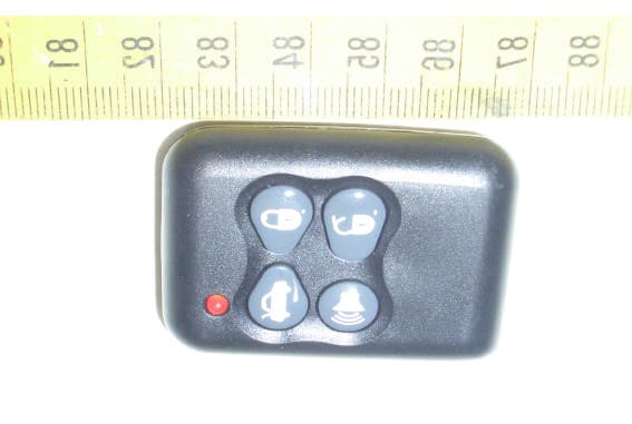
Click to zoom
Application Details
- Equipment Class
- DSC - Part 15 Security/Remote Control Transmitter
- Date of Grant
- Jan 02, 2006
- Application Purpose
- Original Equipment
- Date of Application
- Jan 02, 2006
- Equipment Note
- Transmitter
- Frequency Range
- 315.94200000 - 315.94200000
- Company
- Tech Cast Mfg Corp
- Country
- Taiwan
Documents & Files
Document Text
Text extracted from the exhibit documents filed with the FCC. Open a document above to read the original.
Users Manual
1 TC5001 Operation Manual Name & List of Parts 1. TC2740B MAIN UNIT *1 7. 2P WIRE FOR KILLER *1 2. 4 BUTTON TRANSMITTER *2 8. LED INDICATOR *1 3. SHOCK SENSOR (2 stage) *1 9. PIN SWITCH *2 4. SPEAKER *1 10. MANUAL *1 5. 12P HARNESS *1 11. SCREW PACK *1 6. 6P HARNESS *1 12. OVERRIDE SWITCH *1 Changing TX battery After changing the battery on the code-learned Transmitter, please press any key twice continuously for main unit recognizing the TX. Instruction: 1. Definition of Transmitter’s Buttons: Button Å Button Ç Button É Button Ñ ButtonÅ: a). Arming. b). Silent Arming (Press the button continuously 1.5sec) c). Remote door locking. Buttons Ç: a). Disarming. b). Silent disarming (Press the button continuously 1.5sec) c). Remote door unlocking d). 2 stage disarming while alarm’s triggered Button É: Remote trunk release. Button Ñ: Car-searching/Panic. ButtonÅ + É: anti-robbery ButtonÅ + Ç: optional functions This remote control transmitter provides 2 billions of digital codes with an operative range up to 100 feet, (The operative range will be shorten when system is interrupted or out of power) and also contains Anti-Duplicating & Anti Scanning which is the most secure tool. 2. Micro-Code Learning: Please follow below procedures of code-learning, when renewing or adding more transmitters – a). Turn the car key to the “ON” position, close the car door. b). Make sure all doors are in close position. Press the override switch one time, siren wails and indicator (parking) light blink once in 10 seconds then press override switch two times continuously. c). Siren wails 2 times, LED light flashes rapidly. (Means into code-learning mode) d). Press any button on transmitter once in 10 seconds, when siren wails once means the 1st code learning is done. After that, press another transmitter any button once in 10 seconds, when siren wails twice means the 2nd code learning is done. Following the same procedure, it can learn 6 different transmitter’s code. REMARKIf the transmitter doesn‘t receive any input in 10 seconds, LED light will distinguish. System will leave the code-learning mode and enter to user mode automatically. PP05AAJS 2 3. Disarming-Code set-up and renewing: When disarming, if you are going to renew or add the new transmitter, please follow the following procedures- a). Turn the key to the “ON” position, close the car door. b). Press the override switch one time, siren wails and indicator light blink once in 10 seconds then press override switch 2 times continuously. c). Siren wails 2 times and LED light flashes rapidly (means into code-learning mode) d). Press any button on transmitter in 10 seconds, siren wails 1 time which means the 1 st new transmitter is code-learned. REMARKS: If the transmitter doesn't receive any input numbers or you don't finish the code renewing in 10 seconds while in the code renewing mode, LED light will distinguish. The system will leave the code renewing mode and enter to the user mode automatically. The original code won’t be changed. 4. System will Memorize Status Records Prior to Electricity Cut-Off: Prior to system’s electricity cut-off, system will memorize the status prior to cut-off. At any time, when the electricity is resumed, system will immediately enter into the status prior to cut-off. If system’s electricity is cut-off during override status, then system will immediately enter into “override mode” upon the electricity is resumed. If system’s electricity is cut-off during arming status, then system will immediately enter into “alarm triggering mode” upon the electricity is resumed. 5. Arming: Pressing transmitter button Å, arming mode is set when releasing the button and finds -- a). Siren wails once. b). Central Door Locks locked. c). Indicator (parking) lights blink once. d). Killer enabled. e). Anti-theft status indicator, LED, flashes rapidly After 7 seconds , flashes slowly. f). When connected to power window module, then all power windows will automatically close. 6. Disarming Pressing transmitter button Ç and releasing, you'll find the following conditions. a). siren wails 2 times b). Central door locks unlocked c). Indicator (parking) light blinks 2 times d). Killer disabled e). Anti-theft status indicator, LED, distinguished f). Interior dome-light stays on for 20 seconds then distinguishes. (If within 20 seconds, key on or system re-enters anti-theft mode, then interior dome-light distinguishes). 7. Silent Arming: Pressing transmitter’s button Å for more than 1.5 second then release and you will find -- a). Central Door Locks locked. b). Indicator (parking) lights blink once. c). Killer enabled. d). Anti-theft status indicator, LED, flashes rapidly After 1 minute, flashes slowly. e). When connected to power window module, then all power windows will automatically close. 8. Silent Disarming: Pressing transmitter button Ç for more than 1.5 second then release, and you'll find-- a). Central door locks unlocked b). Indicator (parking) light blinks 2 times c). Killer disabled d). Anti-theft status indicator, LED, distinguished e). Interior dome-light stays on for 20 seconds then distinguishes. (If within 20 seconds, key on or system re-enters anti-theft mode, then interior dome-light distinguishes). 9. Car Searching/Panic: Under the arming mode, press transmitter button Ñ then finds siren wails and indicator (parking) 3 lights and interior dome light blink for 6 seconds then stop. Press button ÇorÑ for early quitting of this mode. 10. Remote anti-robbery When user meets the robbery and the car key is in “on” position and within the remote distance, press the button Å + É for 3 sec., the siren wails and indicator light blinks once which means it’s entering the “remote anti-robbery” mode. When there’s no other action within 30sec., siren will keep on wailing and indicator light blinking. This warning signal will be lasting 30 sec. then “engine cut-off” function will be started. Press button Ç, siren and indicator light stop, “engine cut-off” …
Text truncated - open the document above for the full version.
External Photos
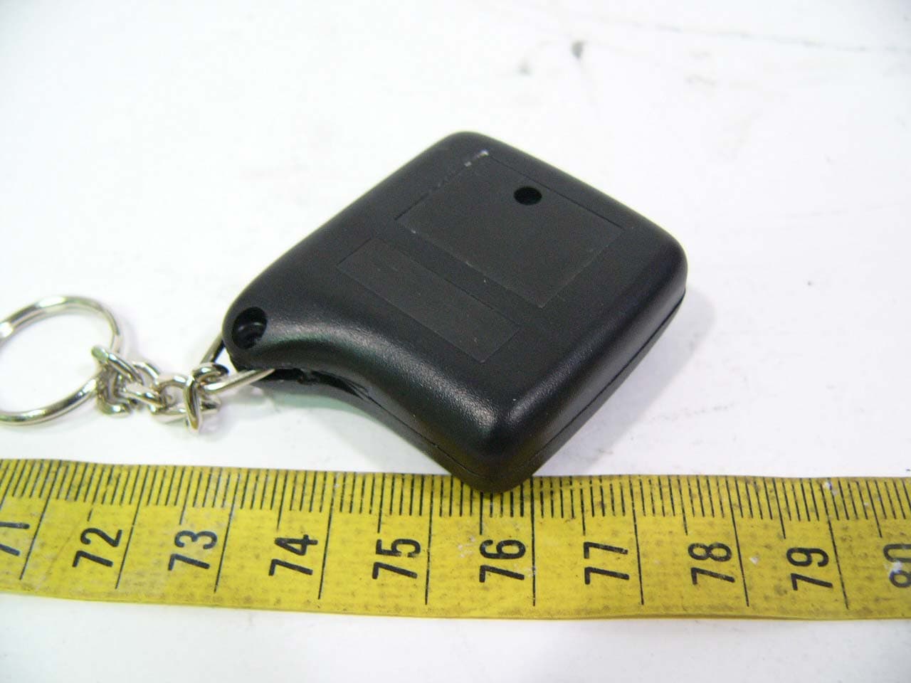
ETC Report No.:ET94R-08-080-01 FCC ID.: JSYTC5001B Rev. No 1.0 CONSTRUCTED PHOTOS of EUT Top View of EUT Bottom View of EUT
ID Label/Location Info
FCCID : JSYTC5001B 20mm 4mm
Internal Photos
ETC Report No.:ET94R-08-080-01 FCC ID.: JSYTC5001B Rev. No 1.0 CONSTRUCTED PHOTOS of EUT Internal View of EUT ETC Report No.:ET94R-08-080-01 FCC ID.: JSYTC5001B Rev. No 1.0 CONSTRUCTED PHOTOS of EUT Component View of Main PCB Solder View of Main PCB
Test Report
Rev. No 1.0 FCC Part 15 EMI TEST REPORT of E.U.T. : Transmitter FCC ID. : JSYTC5001B Model : TC5001 Working Frequency : 315.000 MHz for APPLICANT : Tech-Cast MFG. Corp. ADDRESS : #4-1 Fong Teng Rd., 631 Tai Pei Hsiang Yun Lin Hsien, TAIWAN, R.O.C. Test Performed by ELECTRONICS TESTING CENTER, TAIWAN NO. 34, LIN 5, DING FU TSUN, LINKOU HSIANG TAIPEI HSIEN, TAIWAN, R.O.C. Tel : (02)26023052 Fax : (02)26010910 http://www.etc.org.tw ; e-mail: [email protected] Report Number : ET94R-08-080-01 ETC Report No.:ET94R-08-080-01 FCC ID.: JSYTC5001B Rev. No 1.0 TEST REPORT CERTIFICATION Applicant : Tech-Cast MFG. Corp. #4-1 Fong Teng Rd., 631 Tai Pei Hsiang Yun Lin Hsien, TAIWAN, R.O.C. Manufacture : Tech-Cast MFG. Corp. #4-1 Fong Teng Rd., 631 Tai Pei Hsiang Yun Lin Hsien, TAIWAN, R.O.C. Description of EUT : a) Type of EUT : Transmitter b) Trade Name : ---- c) Model No. : TC5001 d) FCC ID : JSYTC5001B e) Working Frequency : 315.000 MHz f) Power Supply : DC 12V Battery Regulation Applied : FCC Rules and Regulations Part 15 Subpart C (2005) I HEREBY CERTIFY THAT; The data shown in this report were made in accordance with the procedures given in ANSI C63.4 and the energy emitted by the device was founded to be within the limits applicable. I assume full responsibility for accuracy and completeness of these data. Note : 1. The results of the testing report relate only to the items tested. 2. The testing report shall not be reproduced except in full, without the written approval of ETC. Issued Date : Sep. 11, 2005 Test Engineer : ( Kevin Lee ) Approve & Authorized Signer : Will Yauo, Manager EMC Dept. II of ELECTRONICS TESTING CENTER, TAIWAN ETC Report No.:ET94R-08-080-01 FCC ID.: JSYTC5001B Rev. No 1.0 Table of Contents Page 1. GENERAL INFORMATION.....................................................................................................................................................1 1.1 PRODUCT DESCRIPTION...........................................................................................................................................................1 1.2 CHARACTERISTICS OF DEVICE:...............................................................................................................................................1 1.3 TEST METHODOLOGY..............................................................................................................................................................1 1.4 TEST FACILITY..........................................................................................................................................................................1 2. DEFINITION AND LIMITS.......................................................................................................................................................2 2.1 DEFINITION................................................................................................................................................................................2 2.2 RESTRICTED BANDS OF OPERATION.....................................................................................................................................2 2.3 LIMITATION...............................................................................................................................................................................2 2.4 LABELING REQUIREMENT.......................................................................................................................................................4 2.5 USER INFORMATION.................................................................................................................................................................4 3 SYSTEM TEST CONFIGURATION.........................................................................................................................................5 3.1 JUSTIFICATION..........................................................................................................................................................................5 3.2 DEVICES FOR TESTED SYSTEM...............................................................................................................................................5 4. RADIATED EMISSION MEASUREMENT.............................................................................................................................6 4.1 APPLICABLE STANDARD.........................................................................................................................................................6 4.2 MEASUREMENT PROCEDURE..................................................................................................................................................6 4.3 TEST DATA.................................................................................................................................................................................8 4.3.1 Fundanmental and Harmonics......................................................................................................................................8 4.3.2 Other Emission..................................................................................................................................................................9 4.4 FIELD STRENGTH CALCULATION........................................................................................................................................10 4.5 ACTIVATE TIME......................................................................................................................................................................10 4.6 CALCULATION OF DUTY FACTOR.......................................................................................................................................10 4.7 RADIATED TEST EQUIPMENT...............................................................................................................................................15…
Text truncated - open the document above for the full version.
Test Setup Photos
ETC Report No.:ET94R-08-080-01 FCC ID.: JSYTC5001B Rev. No 1.0 Radiated Measurement Photos
Contact Information
Applicant
Chou(Daniel J C., General Manager)
Test Firm
Electronics Testing Center, TaiwanWill Yauo
Technical Specifications
| # | Rule Parts | Frequency Range | Power Output |
|---|---|---|---|
| 1 | 15.231 | 315.942 MHz - 315.942 MHz | - |
Other Applications from Tech Cast Mfg Corp
JSYTC2520C
Sep 28, 2005Easy Alarm
Equipment Class
DSC - Part 15 Security/Remote Control Transmitter
JSYTC2720
Jul 19, 1998CRR - Superregenerative Receiver
Equipment Class
CRR - Superregenerative Receiver
JSYTC2520
Jul 19, 1998CRR - Superregenerative Receiver
Equipment Class
CRR - Superregenerative Receiver
JSYTC3001B
Jun 23, 1998Car Alarm Transmitter
Equipment Class
DSC - Part 15 Security/Remote Control Transmitter
JSYQA202C
Jun 23, 1998Car Alarm Transmitter
Equipment Class
DSC - Part 15 Security/Remote Control Transmitter