JTEWLS4Communications Receiver
Andrew Network Solutions Group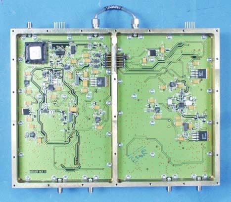
Click to zoom
Application Details
- Equipment Class
- CXX - Communications Rcvr for use w/ licensed Tx and CBs
- Date of Grant
- Jul 09, 2001
- Application Purpose
- Original Equipment
- Date of Application
- Jul 09, 2001
- Equipment Note
- Communications Receiver
- Frequency Range
- 806.00000000 - 849.00000000
- Country
- United States
Documents & Files
Document Text
Text extracted from the exhibit documents filed with the FCC. Open a document above to read the original.
Users Manual
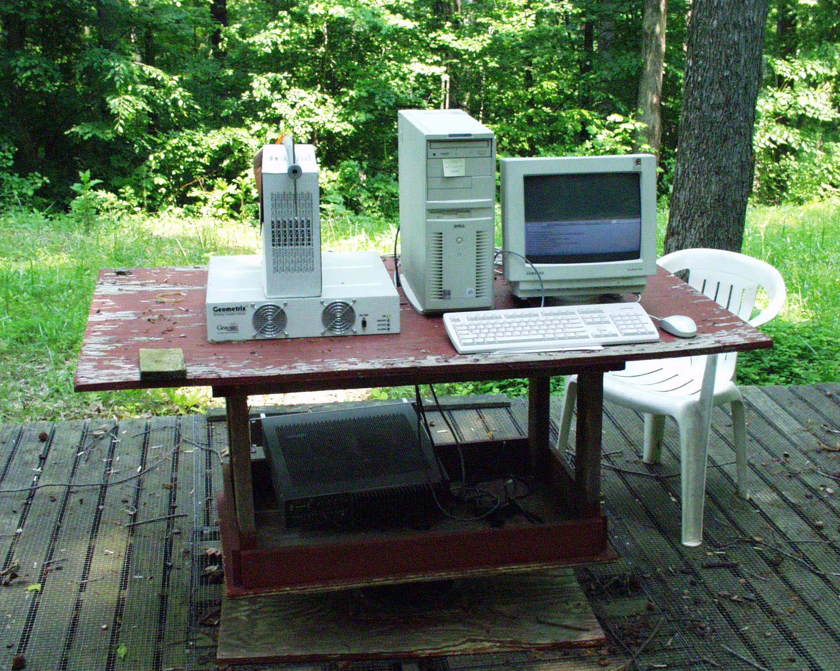
Testing Procedures This procedure is used to determine the basic functionally of a four-channel TDOA Geometrix Wireless Location Sensor (WLS) after installation has been completed. Equipment Required One Laptop Computer (See Table 2 for description) One Crossover Cable (See Table 2 for description) One Loopback Connector (See Table 2 for description) Initialization The link between the computing device and the WLS needs to be established. The following steps will establish that connection. Step 1. At the DeskTop, right click on the Network Neighborhood icon and select properties. Depending on the operating system, the keystrokes will differ slightly as to network setup. Step 2. Select the TCP/IP NIC. Step 3. Type the IP address of 10.1.1.200, and a subnet mask of 255.255.255.0. If the GCS is in place and connected to the network, and the WLS is properly connected to the network, the green online light on the front of the unit will be illuminated a few minutes following power-up. Step 4. Connect the WLS to a computing device via a crossover cable and plug into the10- Base-T port on the rear panel of the WLS. Step 5. Power up the WLS. Step 6. After the computing device has booted up, select the QvtTerm plus in the systems application menu. Step 7. Open a session and enter an IP address of 10.1.1.1 in the address window of the WLS to be tested. Step 8. Select default in the configuration window, and click the OK button. This will bring up the login prompt. Step 9. Enter root and a # prompt will be displayed. When power is applied and connectivity is established between the GCS and WLS, the green online LED will illuminate on the front panel. This will take roughly 1 minute. When this occurs the GCS will perform codecheck, which will determine if the software is up to date with the latest software. At this point the GCS will notice that the software is not up to the latest software and will begin downloading new versions of code to the WLS. After the code has been downloaded to the WLS, a reboot is issued and the online LED will go off. When the WLS boots up once again and establishes connectivity to the GCS the online LED will illuminate once again. These processes should be completed in roughly two minutes. If this process fails, login to the WLS as above and type the command ./stop_reboot. If all indications are correct, proceed to Step 10. Step 10. At the # prompt enter the command: start The program will go through a series of initializations and when the screen reads started watchdog, hit the enter key and a # prompt will appear. Step 11. At the # prompt enter the command: ./stop_reboot This will stop the unit from rebooting if the unit does not see a network connection. Step 12. At the # prompt enter the command: ./stop_processes . Step 13. Type pwd on the command line. Step 14. Hit enter to determine the directory structure, this should be /ram/bpu/tester. Step 15. At the command line type: testCtrl This will bring up the TESTCTRL Main Menu. Step 16. Select 2 backplane control menu. This is the area where tests from the backplane are run. Test LED’s on the front panel Step 1. Select 3 to test Alarm LED. Step 2. Select 1 to turn on the LED. ( the LED should illuminate) Step 3. Select 3 to test Alarm LED. Step 4. Select 0 to turn off the LED. (the LED turn off) Step 5. Select 4 to test Active LED. Step 6. Select 1 to turn on the LED. ( the LED should illuminate) Step 7. Select 0 to turn off the LED. (the LED turn off) Step 8. Select 5 to test Online LED. Step 9. Select 1 to turn on the LED. ( the LED should illuminate) Step 10. Select 0 to turn off the LED. (the LED turn off) Confirm Status Word Step 1. Select 1 to read Status Word. Status Word should read as follows: Backplane Status Word BPU1 Fault: OK BPU2 Fault: OK 39 MHz Reference Oscillator Locked 10 MHz Reference Oscillator Present Over temperature (over 83d C) False Over 14d C (factory test) True +12V OK... OK +7V Supply OK -7V Supply OK 10 MHz Reference Enabled Trigger Out Value Logic 0 Supply Shutdown Supply On +5V Supply OK PLL Alarm Lockout Disabled If the data reads anything other than the above, contact engineering to determine the severity of the problem. Step 2 . Select 0 to go back to TESTCTRL main menu. Step 3 . Select 3 to go to Backplane SPROM Control Menu. Step 4. Select 6 Read System Delay Data. Verify that a table exist, disregard the numbers in the table. Step 5. Select 0 to go back to Backplane SPROM main menu. Step 6. Select 0 to go back to testCtrl main menu. Step 7 . Select 0 to go back to # prompt. Testing the WAN & COMM Ports The following tests require loopback connectors for the WAN & COMM ports. The loopback connectors MUST be installed prior to running the tests. If the ONLINE light on the front panel is on, the WAN connection is present. Proceed to Step 4 for the COMM port test. If not proceed to step 1. Step 1. Install the 25 pin loopback connector for the WAN test. See Diagram 4, page 47 for pin connections. Step 2. When at the # prompt, type the command: testWAN. Watch for pass/fail reply. (Loopback Succeeded). Step 3. Remove the loopback connector. Step 4. Install the 9 pin loopback connector for the COMM test. See Diagram 5, page 47 for pin connections. Step 5. When at the # prompt, type the command: testCOM. Watch for pass/fail reply. (Loopback Succeeded) Step 6 . Remove the loopback connector. If the data reads anything other than the above, contact engineering to determine the severity of the problem. Testing The BPU Board Step 1 . Change directory with the command: cd /ram/bpu/qnx/bin. Step 2. When at the # prompt, type the command: btest-b0. This will test bpu0. All tests should say passed or skipped. The end of the test should read btest ok. Step 3. When at the # prompt, type the command: btest-b1. This will test bpu1. All tests should say passed or skipped. The end of the test should read btest ok. NOTE: The bpu.ini file in the /ram/bpu/qnx/config directory needs to be activated for the 2 …
Text truncated - open the document above for the full version.
Cover Letter(s)
140 Vista Centre Drive Forest, Virginia 24551 • U.S.A. Phone: 804-386- 5300 FAX: 804-386-5320 June 27, 2001 Federal Communications Commission Authorization & Evaluation Division 7435 Oakland Mills Road Columbia, MD 21046 Ref: Confidentiality Request; FCC ID: JTEWLS4 In connection with our submission of the above referenced product for FCC approval, (applicant/grantee) is requesting confidentiality of certain sections of the accompanying application. The exhibit for which confidentiality is requested is: Block Diagram. This request is made under the provisions of Section 0.457(d) of the Commission’s Rules, and Section 552(b)(4) of the Freedom of Information Act. The material for which confidentiality is requested falls within the scope of Section 552(b)(4) as trade secrets and includes material covered by Section 0.459 of the Commission’s Rules. Sincerely, R. K. Bell Director
External Photos
Right Side View Top View Left Side View Bottom View Back View Front View
ID Label/Location Info
WLS LABEL DESIGN AND LOCATION 6/14/01 Note: Labels are rotated 90 degrees when assembled to the WLS. ID Labels will also contain the following statement: “This device complies with Part 15 of the FCC Rules. Operation is subject to the condition that this device does not cause harmful interference.” JTEWLS4 Label text FCC Label REAR VIEW OF JTEWLS4 GRAYSON WIRELESS SER# 12345678 6/14/01 WLS4-24-M FCC ID: JTEWLS4
Internal Photos
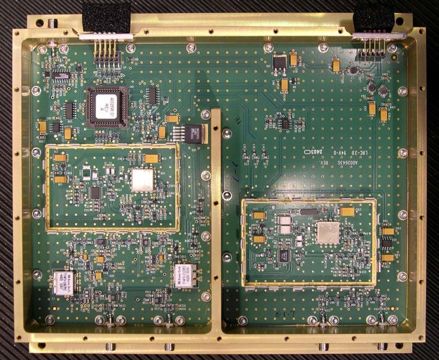
Interior Top View Interior Bottom View Multiplexer, Top Multiplexer, Bottom Module A, Top Module A, Bottom Module B, Top w/shields Module B, Top w/o shields Module B, Bottom
Test Report
ENGINEERING STATEMENT In Regard to Measurements on GRAYSON ELECTRONICS COMPANY MODEL: WSL4 FCC ID: JTEWSL4 A. INTRODUCTION Hyak Laboratories, Inc. has been authorized by Grayson Electronics Company to determine compliance with FCC rules, Part 15, Subpart B. The device operates in the 806 - 849 MHz band and is intended for use as a location sensor. B. DESCRIPTION OF DEVICE The device incorporates a dual conversion, super-heterodyne design. The following information is supplied as requested in FCC Bulletin OCE 24: 1. Service in which the device will be used: Part 15 (22). 2. Function of device: Location Sensor for cellular systems. 3. Tuning range: 806 - 849 MHz. 4. IF used: 240 MHz; 5 MHz 5. Fundamental frequency of principal oscillators in the device. First local oscillator: (F o +240) MHz (PLL). Second local oscillator 245 MHz. C. DESCRIPTION OF MEASUREMENT FACILITIES A description of the Hyak Laboratories' radiation test facility is a matter of record with the FCC. The facility was accepted for radiation measurements from 30 to 1000 MHz on October 1, 1976, and is currently listed as an accepted site. D. DESCRIPTION OF MEASUREMENT PROCEDURE: RADIATED EMISSIONS Measurements of radiated field strength were made using ANSI C63.4 (1992) as the basic procedure. Measurements were made with 3-meter spacing between the device under test and the test equipment antenna. The antenna(s) connected to the device under test consisted of a vertically polarized, dipole antenna approximately 10 cm long. The device under test was placed on a rotatable table 80 cm in height. Measurement of field strength was made through use of Tektronix 494P spectrum analyzer in conjunction with Singer DM- 105A series or EMCO 3221 calibrated dipoles or EMCO 3115 DRG horn. For each spurious emission identified between 30 to 5500 MHz (per Para 15.33(b)(1)), the test sample was rotated for maximum pickup, the test antenna varied in elevation, and the test antenna polarization shifted between horizontal to vertical in order to maximize observed signals. E. REPORT OF RADIATED EMISSIONS 1. Table 1 lists the frequency and amplitude of all signals observed from 30 to 5500 MHz including those 20 dB below the limits of paragraph 15.109 of the FCC Rules. 2. Emissions from associated processor were within Class A verification limits. 2 TABLE 1 RADIATED SPURIOUS EMISSIONS Measured at 3 meters PART 15(B) PARA. 15.109 Frequency Frequency To Which of Meter Antenna Field 1 Tuned Emission Reading Factor Intensity FCC Limit dB to (MHz) (MHz) (dBm) (dB) uV/m @ 3m uV/m @ 3m Limit 806.000 1046.00 -101.6 24.5 31.3 500 -24 827.500 1067.50 -100.0 24.5 36 500 -23 849.000 1089.00 -100.0 24.6 38 500 -22 Note 1: uV/m = Log -1dBu/m 20 dBu = dBm + antenna factor + 107 All other emissions were more than 20 dB below FCC limit. RADIATED SPURIOUS EMISSIONS FCC ID: JTEWSL4 TABLE 1 3 F. PROCEDURE - AC LINE CONDUCTED SPURIOUS The WLS4 operates from cell site/central office house dc battery supplies; there is no connection to ac power lines. G. STATEMENT Technical test data are from tests performed by me or under my supervision. My qualifications are a matter of record with the Federal Communications Commission. I personally attest to the accuracy of the test data submitted as a part of this engineering statement. __________________________________ Rowland S. Johnson Dated: June 11, 2001 4
Contact Information
Applicant
Kent Bell(Director of Hardware Engineering)
Test Firm
Hyak Laboratories, Inc.Rowland Johnson
703-451-1188
Technical Specifications
| # | Rule Parts | Frequency Range | Power Output |
|---|---|---|---|
| 1 | 15B | 806 MHz - 849 MHz | - |
Other Applications from Andrew Network Solutions Group
JTEWLS2NS
Jan 06, 2004GEOMETRIX WIRELESS LOCATION SENSOR RECEIVER
Equipment Class
CXX - Communications Rcvr for use w/ licensed Tx and CBs
JTEWLS4NS
Jan 05, 2004GEOMETRIX WIRELESS LOCATION SENSOR RECEIVER
Equipment Class
CXX - Communications Rcvr for use w/ licensed Tx and CBs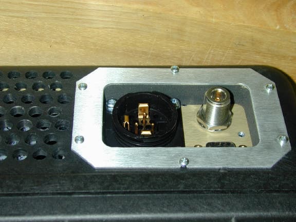
JTEGWMT1920
Dec 20, 2001Test transmitter
Equipment Class
PCB - PCS Licensed Transmitter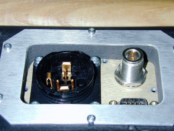
JTEGWMT0820
Dec 17, 2001Test transmitter
Equipment Class
TNB - Licensed Non-Broadcast Station Transmitter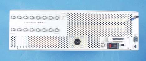
JTEWLS2
Jul 09, 2001Communications Receiver
Equipment Class
CXX - Communications Rcvr for use w/ licensed Tx and CBs