JXJTRON40GPSEPIRB Class A FLOAT FREE
Jotron Electronics A/S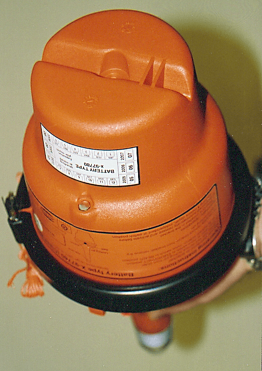
Click to zoom
Application Details
- Equipment Class
- GEP - 406 MHz EPIRB
- Date of Grant
- Jun 03, 2003
- Application Purpose
- Original Equipment
- Date of Application
- Apr 03, 2003
- Equipment Note
- EPIRB Class A FLOAT FREE
- Frequency Range
- 121.50000000 - 121.50000000
- Company
- Jotron Electronics A/S
- Country
- Norway
Documents & Files
Document Text
Text extracted from the exhibit documents filed with the FCC. Open a document above to read the original.
Users Manual
Tron 40GPS your safety – our concern OPERATORS MANUAL JOTRON Electronics a.s P.O.Box 54, NO-3280 Tjodalyng, Norway Tel: +47 33 13 97 00, Fax: +47 33 12 67 80 www.jotron.com www.los-grafisk.no - 223310 United Kingdom Marconi International Co Ltd Pembrokeshire Tel +44 1646 697954 Fax +44 1646 697954 United Kingdom Marconi International Co Ltd Silvertown, London Tel +44 20 7 5114391 Fax +44 20 7 5114483 United Kingdom Marconi International Co Ltd Southampton, Hants Tel +44 23 80 224767 Fax +44 23 80 333644 United Kingdom Marconi International Co Ltd Suffolk Tel +44 1502 572365 Fax +44 1502 508955 United Kingdom Marconi International Co Ltd Suffolk Tel +44 1394 613138 Fax +44 1394 675247 United Kingdom Marine Electronic Supplies Southampton, Hants Tel +44 2380 663316 Fax +44 2380 663241 United Kingdom Mark Electronics Hants Tel +44 1590 671144 Fax +44 1590 679517 United Kingdom Nationwide Marine Hire Cheshire Tel +44 1925 245788 Fax +44 1925 245788 [email protected] United Kingdom Premium Liferaft Services Essex Tel +44 1621 784858 Fax +44 1621 785934 United Kingdom Radio Electronic Service Ltd Guernsey Tel +44 1481 728837 Fax +44 1481 7143794 United Kingdom Ships Electronic Services Stirlingshire Tel +44 1324 666886 Fax +44 1324 666033 United Kingdom Ships Electronic Services Tyne & Wear Tel +44 191 4832236 Fax +44 191 4832331 [email protected] United Kingdom Ships Electronoic Services Ltd Rochester, Kent Tel +44 1634 295500 Fax +44 1634 295536 United Kingdom SM Group (Europe) Ltd Plymouth Tel +44 1752 66599 Fax +44 1752 222717 United Kingdom T.S.A Communications Limited Merseyside Tel +44 151 6478100 Fax +44 151 6478120 United Kingdom XM Yachting Ltd East Sussex Tel +44 1323 870092 Fax +44 1323 870909 United States *High Seas Trading Co. Miami, Florida Tel +1 305 3587455 Fax +1 305 350 6887 [email protected] United States *Mackay Marine Miami Tel +1 305 591 3399 Fax +1 305 591 1879 [email protected] www.mackaycomm.com United States *Radio Holland USA Inc. Houston, Texas Tel +1 713 378 2100 Fax +1 713 378 2101 [email protected] www.radiohollandusa.com United States Radio Holland USA Inc. Corpus Christi, TX Tel +1 361 883 5283 Fax +1 361 883 5285 [email protected] www.radiohollandusa.com United States Radio Holland USA Inc. Hollywood, FL Tel +1 954 920 8400 Fax +1 954 920 8455 [email protected] www.radiohollandusa.com United States Radio Holland USA Inc. Kenilworth, NJ Tel +1 908 298 9100 Fax +1 908 298 9118 [email protected] www.radiohollandusa.com United States Radio Holland USA Inc. Long Beach, CA Tel +1 562 535 0039 Fax +1 562 988 0236 [email protected] www.radiohollandusa.com United States Radio Holland USA Inc. Harahan, LA Tel +1 504 7334024 Fax +1 504 7334027 [email protected] www.radiohollandusa.com United States Radio Holland USA Inc. Seattle, WA Tel +1 206 768 1601 Fax +1 206 768 1603 [email protected] www.radiohollandusa.com United States Radio Holland USA Inc. Chesapeake, VA Tel +1 757 436 2360 Fax +1 757 436 4809 [email protected] www.radiohollandusa.com United States Radio Holland USA, Inc. Mobile, AL Tel +1 334 432 3109 Fax +1 334 433 8223 [email protected] Uruguay *Electromarítima Uruguaya Ltda Montevideo Tel +598 2 924 7789 Fax +598 2 924 7138 [email protected] Venezuela *Radio Marina de Venezuela S.A. Maracaibo Edo. Zulia Tel +58 261 7987811 Fax +58 261 7982596 [email protected] 35 IMPORTANT! Jotron Electronics a.s. is a prime manufacturer of safety equipment designed for rescue of human lives and their property. For safety equipment to be effective in line with the design parameters it is important that they are handled, stowed and maintained in compliance with the manufacturers instructions. Jotron Electronics a.s. can not be held responsible for any damage caused due to incorrect use of the equipment or breach of laid down procedures or for failure of any speci- fic component or other parts of the equipment. The chapter covering battery replacement (5.1) is added for information only. Jotron Electronics a.s. does not take any responsibility for improper disassemb- ling/assemblin of the beacon. We strongly recommend all service to be done by authorized Jotron agents. In addition to normal service, Jotron agents have the necessary equipment and education to test the operational functions of the beacon. The information in this book has been carefully checked and is believed to be accurate. However, no responsibility is assumed for inaccuracies. CAUTION! This equipment contains CMOS integrated circuits. Observe handling precautions to avoid static discharges which may damage these devices. JOTRON electronics a.s reserves the right to make changes without further notice to any products or modules described herein to improve reliability, function or design. JOTRON electronic a.s does not assume any liability arising out of the application or use of the described product. The equipment complies with the following Directives: MED 96/98/EC EMC 89/336/EEC Harmonized Standards applied in order to verify compliance with the Directive(s): ETSI 300 066:1996 EN 60945:1997 EC Declaration of Conformity, available at www.jotron.com 3 CHANGESRECORD NO.CHAPTERVERSION NEW MANUALEM3829–A NEW TEXTEM39035B NEW TEXTEM39441.6, 3.1, 4.1, 5, 5.1, 5.2, 5.7, 6.1, FIG. 5B REVISION HISTORY TABLE OF CONTENTS 4 Glossary ...............................................................5 Battery Safety Data Sheet ................................6 Radio Log Instructions ......................................7 Test of radio equipment ...............................7-8 Test and Maintenance Record ........................9 1. INTRODUCTION ......................................10 1.1 General ........................................................10 1.2 System Description ..................................11 1.3 Signal Detection ...............................…
Text truncated - open the document above for the full version.
Attestation Statements
EC Declaration of Conformity Manufacturer: Jotron Electronics AS Kirkestien 1 P. O. Box 54 3280 Tjodalyng NORWAY Type/Model: Tron 40 GPS Description: Emergency transmitter float free with GPS The equipment complies with the following Directives: MED 96/98/EC EMC 89/336/EEC Harmonized Standards applied in order to verify compliance with the Directive(s): ETS 300 066:1996 EN 60945:1997 Test reports/Certificate(s) issued by Notified Body: Det Norske Veritas AS ID no. 0434 Veritasvn. 1 1322 Hoevik NORWAY EU Type Examination Certificate no. and date: MED-D-216, dated 2001-07-05 Date: 7 th July 2001 Signature: Steinar Sæter Managing Director
Cover Letter(s)
Re: Correspondence Reference Number: 25218, 731 CN: EA384636 Stan, Answers to your questions: 1.) Submit a FCC test report required by Sections 2.1046 thru 2.1057 of the Commission's R&R. The test report should include the 406.025 MHz data and the 121.5 MHz GMDSS data. Answer: This should be included in the RTCM report chapt 12. If not, please tell me where to find Sections 2.1046 thru 2.1057 so we can give the correct information. 2.) What is the output power, frequency tolerance and the emission designator for GMDSS 121.5 MHz? Answer: output power 20dBm +/- 3dB frequency tolerance: +/- 10ppm emission designator for GMDSS 121.5 MHz: 3K20A3X Please answer directly to me. Sincerely, Jotron Electronics as, Eirik Storjordet Certification Manager Tel: +47 33139714 Fax: +47 33126780 E-mail: [email protected]
ID Label/Location Info
Label X-97939
ID Label/Location Info
Label X-97939
Test Report
Chapt. 1 ADMINISTRATION, GENERAL COMMENTS AND SUMMARY OF TESTS Chapt. 2 A 2.0: INITIAL ALIVENESS TEST Chapt. 3 A 3.0 DRY HEAT TEST Chapt. 4 A 4.0 DAMP HEAT TEST Chapt. 5 A 5.0 VIBRATION TEST Chapt. 6 A 6.0 BUMP TEST Chapt. 7 A 7.0 SALT FOG TEST Chapt. 8 A 8.0 DROP TESTS Chapt. 9 A 9.0 LEKAGE AND IMMERSION TESTS Chapt. 10 A 10.0 SPURIOUS EMISSION TEST Chapt. 11 A 11.0 THERMAL SHOCK TESTS Chapt. 12 A 12.0 COSPAS-SARSAT C/S T.007 TESTS Chapt. 13 A 13.0 OPERATIONAL LIFE, STROBE LIGHT AND SELF TESTS Chapt. 14 A 14.0 AUTOMATIC RELEASE MECHANISM & AUTOMATIC ACTIVATION TESTS Chapt. 15 A 15.0 STABILITY & BUOYANCY TESTS (SEE ALSO QINETIQ BUOYANCY TESTS ADDED BY JOTRON) Chapt. 16 A 16.0 INADVERTENT ACTIVATION TEST Chapt. 17 A 17.0 AUXILLARY RADIO-LOCATING DEVICE TRANSMITTER TEST Chapt. 18 A 18.0 HUMIDITY TEST Chapt. 19 A 19.0 ORIENTATION TEST 2
Test Report
FRASER, PORTSMOUTH PO4 9LJ Date of Issue:31 st January 2002Cert. No.:NTT-11/01-C01 QinetiQ/S&E/SPS/ TT-11/01-1.0 Sheet 1 of 9 Marine Approvals and Testing Service Type Test/Inspection Certificate RTCM SC110 EPIRB V2, Section 15 Equipment under Test.Date EUT Received:16-11-01 Date of Test: 22-11-01 Manufacturer: JOTRON ELECTRONIC AS Address: P.O. Box 54, N-3280 Tjodalyng, NORWAY Units Comprising “ Equipment’s under Test “ DescriptionType NumberRemarks 1EPIRB BeaconTRON 40GPSS/N OLA 00035 2C/w Battery PackX-97780Class 2 Representative System / Configuration Notes The objective was to verify compliance with the Buoyancy requirements of section A15.0. In particular to prove that the Tron 40GPS does meet the excess buoyancy requirement. A beacon of the same type and build has been subject to all of the tests required by the RTCM Document SC110 EPIRB Version 2 at the Interspace test Lab in France. Unfortunately the tests for buoyancy (section A15.0) had seemingly been carried out incorrectly or with a flawed test method or analysis, and the results were either inconclusive or indicated failure. This report details the conduct of this test using the standard accredited test method used at QinetiQ, Fraser Range and additionally repeats the test using two alternative test methods to confirm the result gained. A series of photographs to record the nature of each test method is provided as an Annex. TEST PROCEDURES (see Annex A, Photographs) Preconditioning: The beacon was examine and subjected to an “aliveness” test (test A11) to confirm that the sample under test was representative of the type and fully operational before testing commenced. This was conducted in an anechoic screened room. (Photo 1) Because the beacon was not coded with “test” protocol the sea water switch contacts were covered with plastic tape to prevent any inadvertent activation and distress transmissions. Result:It was confirmed the TRON 40GPS Beacon was a standard production unit and that it passed the aliveness test. The weighing scales were calibrated using the set of class F1 test weights in accordance with Work Instruction for weighing machines. They were confirmed to be within ±4 grams. Test Procedure 1.(This is the standard accredited test method in the QinetiQ Lab) Date of Issue:31 st January 2002Cert. No.:NTT-11/01-C01 QinetiQ/S&E/SPS/ TT-11/01-1.0 Sheet 2 of 9 Marine Approvals and Testing Service Type Test/Inspection Certificate - RTCM SC110 EPRB V2, Section 15 This is essentially A15, method 1 from the RTCM standard. The EPIRB Beacon was placed on the platform of the weighing machine and the dry weight of the beacon was recorded from the digital readout. The EPIRB Beacon was then fitted with lightweight harness to enable it to be pulled under the water surface. This was connected by nylon cord through a small pulley fixed to the bottom of the test tank and then up out of the water and there connected to the weighing scales. The scales were positioned on the platform of a hydraulic lifting device. The beacon was allowed to float naturally on the water in the test tank. See Photo 2. The platform of the Hydraulic lift was raised slightly to take the slack out of the connecting cord but without introducing any tension. The weighing scales were zeroed with the Tare control. The platform of the Hydraulic lift was then raised steadily until the beacon was just submerged. See Photo 3. The reading on the digital readout of the weighing scale was recorded. Results:Dry weight of beacon (mass)2016 grams Force needed to submerge beacon883 grams When the beacon is floating naturally it is supporting its own mass by the displacement of water, the force needed to submerge the beacon from this position is a measure of excess buoyancy. ∴ ∴∴ ∴ total buoyant force = 2016 + 883 = 2899 grams excess buoyancy factor = (2899 / 2016) = 1.438 Test Procedure 2.(Volume ratio) This is essentially A15, method 2 from the RTCM standard. Practical designs of EPIRB beacons are complex shapes that do not readily allow calculation of the volume above and below the waterline. This method measures the volume by a practical procedure. The test tank is fitted with an overflow pipe The test tank was filled with water until water flows from the overflow the tank is then left to enable the water level to normalise so that no further drips emerge from the overflow pipe. The EPIRB Beacon was then gently introduced into the test tank and allowed to float naturally on the water. The overflowing water from the overflow pipe was collected in a glass measuring flask. The water level was given sufficient time to allow it to normalise so that no further drips emerge from the overflow pipe. See Photo 4. The volume of water collected in the measuring flask was recorded this would represent the volume below the waterline. The measuring flask was emptied and replaced under the overflow pipe Then using controlled finger pressure on the top of the beacon it was lowered into the test tank such that it was just submerged. Again the water level was given sufficient time to allow it to normalise so that no further drips emerge from the overflow pipe. See Photo 4. Date of Issue:31 st January 2002Cert. No.:NTT-11/01-C01 QinetiQ/S&E/SPS/ TT-11/01-1.0 Sheet 3 of 9 Marine Approvals and Testing Service Type Test/Inspection Certificate - RTCM SC110 EPRB V2, Section 15 The volume of water collected in the measuring flask was recorded, this would represent the volume above the waterline. Results:Volume below waterline2065 millilitres. Volume above waterline895 millilitres. The volume below the waterline represents the displacement of water needed to support the mass of the beacon, the volume above the waterline represents a potential displacement that could support an excess mass. The excess buoyancy factor is a ratio of the total volume divided by the volume needed to support the mass of the beacon. ∴ ∴∴ ∴ total volume of beacon = 2065 + 895 = 2960 millilitres excess buoyancy factor =…
Text truncated - open the document above for the full version.
Contact Information
Applicant
Sten Frizell
Technical Contact
Non-Technical Contact
Jotron Electronics A/SEirik Storjordet
[email protected]+4733139700
Technical Specifications
| # | Rule Parts | Frequency Range | Power Output | Emission | Tolerance |
|---|---|---|---|---|---|
| 2 | 80.1101(c)(5) | 121.5 MHz - 121.5 MHz | 100.00 mW | 3K20A3X | 10 ppm |
Other Applications from Jotron Electronics A/S
JXJTRON40S
Oct 26, 2000(See comments below)
Equipment Class
GEP - 406 MHz EPIRBJXJTRONVHF
Mar 19, 1995GHH - Part 80 VHF Hand Held Transmitter (GMDSS)
Equipment Class
GHH - Part 80 VHF Hand Held Transmitter (GMDSS)JXJTRONSART
Mar 24, 1993SRT - Radar Transponder
Equipment Class
SRT - Radar Transponder