K3XWTX001433.92MHz REMOTE CONTROL TRANSMITTER
Warn Industries Inc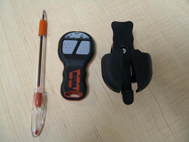
Click to zoom
Application Details
- Equipment Class
- DSC - Part 15 Security/Remote Control Transmitter
- Date of Grant
- Apr 04, 2007
- Application Purpose
- Original Equipment
- Date of Application
- Apr 04, 2007
- Equipment Note
- 433.92MHz REMOTE CONTROL TRANSMITTER
- Frequency Range
- 433.92000000 - 433.92000000
- Company
- Warn Industries Inc
- Country
- United States
Documents & Files
Document Text
Text extracted from the exhibit documents filed with the FCC. Open a document above to read the original.
Users Manual
Contents English . . . . . . . . . . . . . . . . . . . . . . . . . . . . . .1 Français . . . . . . . . . . . . . . . . . . . . . . . . . . . . .11 Deutsch . . . . . . . . . . . . . . . . . . . . . . . . . . . . .21 Español . . . . . . . . . . . . . . . . . . . . . . . . . . . . .31 Svenska . . . . . . . . . . . . . . . . . . . . . . . . . . . .41 Italiano . . . . . . . . . . . . . . . . . . . . . . . . . . . . . .51 Suomi . . . . . . . . . . . . . . . . . . . . . . . . . . . . . .61 WARN Wireless Control Installation Guide 1 As you read these instructions, you will see WARNINGS, CAUTIONS, NOTICES and NOTES. Each message has a specific purpose. WARNINGS are safety messages that indicate a potentially hazardous situation, which, if not avoided could result in serious injury. CAUTIONS are safety messages that indicate a potentially hazardous situation which, if not avoided, may result in minor or moderate injury. A CAUTION may also be used to alert against unsafe practice. CAUTIONS and WARNINGS identify the hazard, indicate how to avoid hazard, and advise of the probable consequence of not avoiding the hazard. NOTICES are messages to avoid property damage. NOTES are additional information to help you complete a procedure. PLEASE WORK SAFELY! GENERAL SAFETY PRECAUTIONS WARNING WARNING WARNING FALLING OR CRUSHING HAZARD Failure to observe these instructions could lead to severe injury or death. •Neveruse winch to lift or move persons. •Neveruse winch as a hoist or to suspend a load. MOVING PARTS ENTANGLEMENT HAZARD Failure to observe these instructions could lead to severe injury or death. To avoid injury to hands or fingers. •Alwayskeep hands clear of rope, hook loop, hook and fairlead opening during installation, operation, and when spooling in or out. •Alwaysuse extreme caution when handling hook and rope during spooling operations. •Alwaysuse supplied hook strap whenever spooling rope in or out, during installation and during operation. •Alwayskeep vehicle in sight during winching operation. •Alwayswear heavy leather gloves when handling rope. CHEMICAL AND FIRE HAZARD Failure to observe these instructions could lead to severe injury or death. •Alwaysremove jewelry and wear eye protection. •Neverlean over battery while making connections. •Alwaysverify area is clear of fuel lines, fuel tank, brake lines, electrical wires, etc. when drilling. •Neverroute electrical cables: - Across any sharp edges. - Through or near moving parts. - Near parts that become hot. •Alwaysinsulate and protect all exposed wiring and electrical terminals. •Alwaysinstall terminal boots as directed in installation instructions. Warn Industries, Inc. 2 CAUTIONCAUTION MOVING PARTS ENTANGLEMENT HAZARD Failure to observe these instructions could lead to minor or moderate injury. General Safety: •AlwaysKnow Your Winch. Take time to fully read the Installation and Operations Guide, and Basic Guide to Winching Techniques, in order to understand your winch and its operation. •Neveroperate this winch if you are under 16 years of age. •Neveroperate this winch when under the influence of drugs, alcohol or medication. •Neverexceed winch or rope capacity listed on product data sheet. Double line using a snatch block to reduce winch load. •Neveruse winch or rope for towing. Installation Safety: •Alwayschoose a mounting location that is sufficiently strong to withstand the maximum pulling capacity of your winch. •Alwaysuse factory approved mounting hardware, components, and accessories. •Alwaysuse grade 5 or better hardware. •Neverweld mounting bolts. •Alwaysuse care when using longer bolts than those supplied from factory. Bolts that are too long can damage the base and/or prevent the winch from being mounted securely. •Alwaysmount the winch and attach the hook to the rope’s end loop before connecting the electrical wiring. •Alwaysposition fairlead with WARNING label on top. •Alwaysspool the rope onto the drum in the direction specified by the winch warning label on the winch and/or documentation. This is required for the automatic brake to function properly. •Alwaysprestretch rope and respool under load before use. Tightly wound rope reduces chances of "binding", which can damage the rope. MOVING PARTS ENTANGLEMENT HAZARD Failure to observe these instructions could lead to minor or moderate injury. Winching Safety: •Alwaysinspect rope, hook, and slings before operating winch. Damaged components must be replaced before operation. Protect parts from damage. •Neverleave wired remote control plugged into winch when free spooling, rigging, or when the winch is not being used. •Neverhook rope back onto itself. This damages the rope. •Alwaysuse a choker chain, choker rope, or tree trunk protector on the anchor. •Alwaysremove any elementor obstacle that may interfere with safe operation of the winch. •Alwaystake time to use appropriate rigging techniques for a winch pull. •Alwaysbe certain the anchor you select will withstand the load and the strap or chain will not slip. •Neverengage or disengage clutch if winch is under load, rope is in tension or drum is moving. •Neverwinch with less than 5 wraps of rope around the drum, the rope could come loose from the drum. •Nevertouch rope or hook while in tension or under load. •Nevertouch rope or hook while someone else is at the control switch or during winching operation. •Alwaysstand clear of rope and load and keep others away while winching. •Alwaysbe aware of stability of vehicle and load during winching. Alert all bystanders of any unstable condition. •Neveruse a winch to secure a load. Warn Industries, Inc. 70 VASTAANOTTIMEN OHJELMOINTI Kädessä pidettävä kauko-ohjain (lähetin) on ohjelmoitu tehtaalla kommunikoimaan nimenomaisesti oman vastaanottimesi kanssa. Ohjelmointi ei ole tarpeen normaaliolosuhteissa. Mahdollinen vaihtokauko-ohjain on kuitenkin ohjelmoitava kommunikoimaan vastaanottimen kanssa. Toimi seuraavasti: 1. Varmista, että järjestelmä on asennettu ja yhdistetty oikein. 2. Kä…
Text truncated - open the document above for the full version.
Block Diagram
Power Control(12V) Programmable Encoder Local Oscillators Operating At 433.92MHZ Power Amplifier Antenna(RFOUT Frequency:433.92M HZ) TX029a Diagram
External Photos
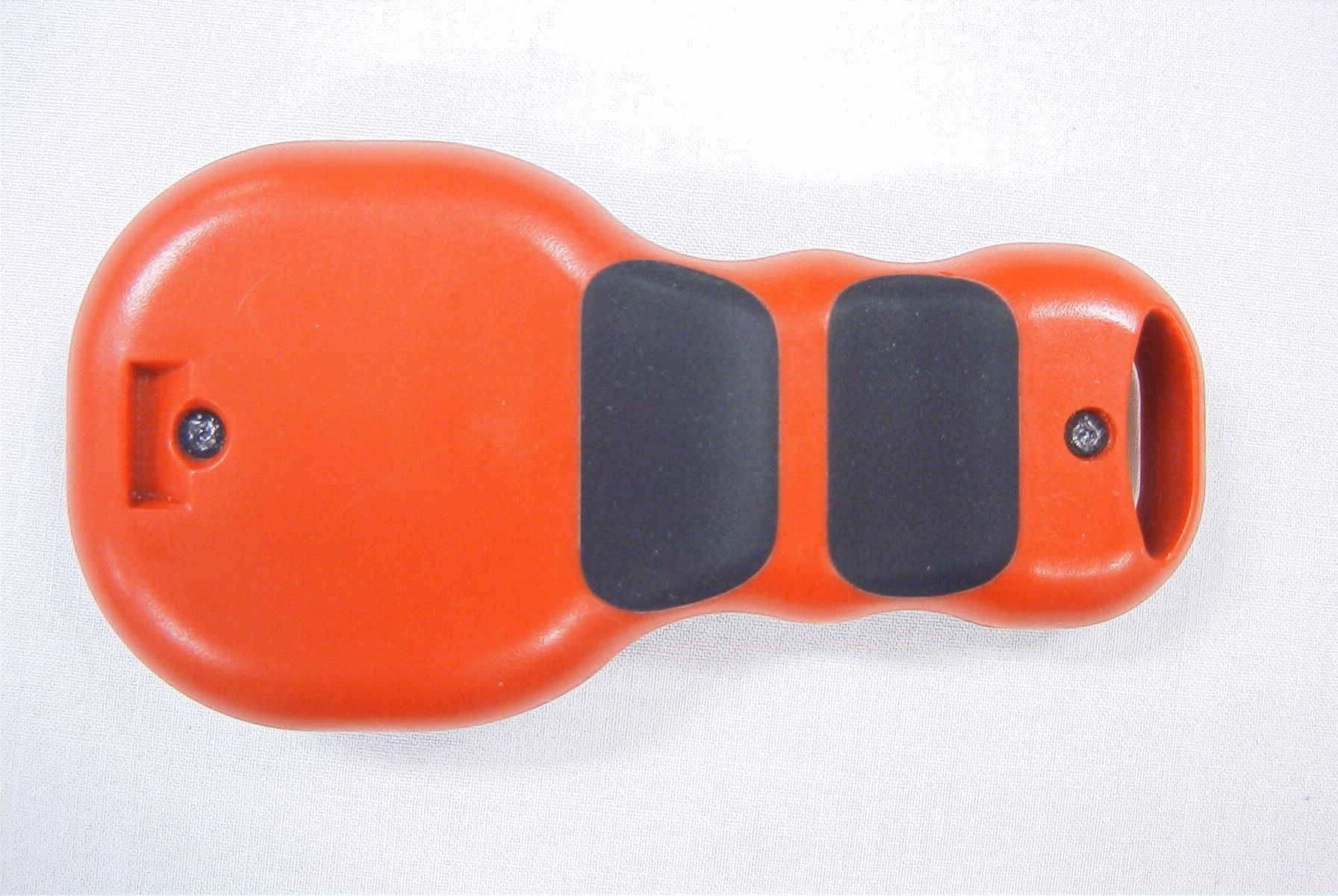
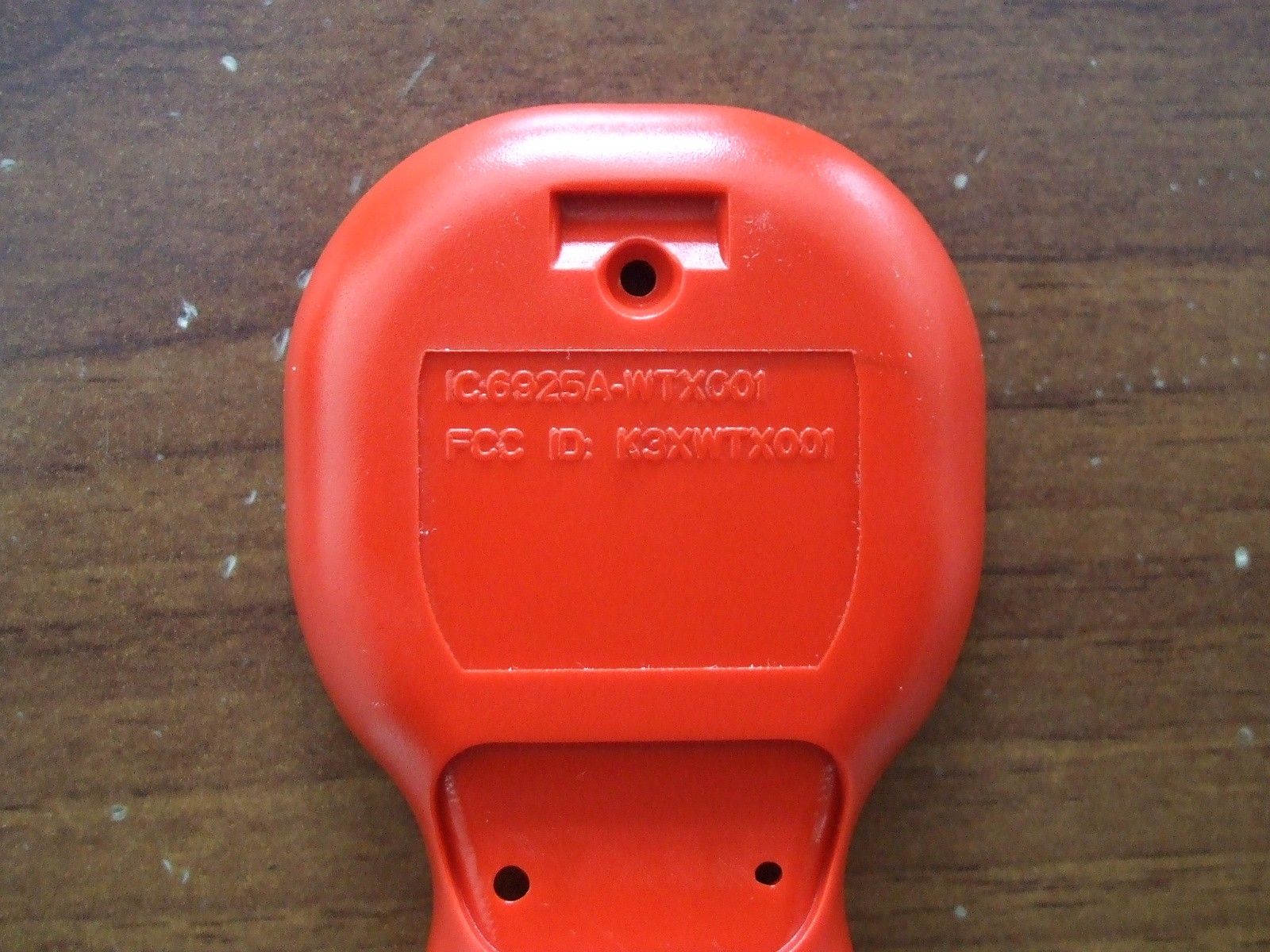
Warn Industries Inc. /External Photos
Internal Photos
Warn Industries Inc. /Internal Photos
Operational Description
Circuit Description 74501 (transmitter) This product uses two 12 volt DC (batteries) to power the internal circuitry. This power is controlled by a programmable encoder which in turn sends signals to a local oscillator (433.92 Mhz) when the transmitters buttons are activated. The oscillator sends its output to a power amplifier which amplifies the signal and sends it to the antenna that is an integral part of the PCB.
Schematics
123456 A B C D 654321 D C B A Title NumberRevisionSize B Date:27-Mar-2007Sheet of File:E:\ (I)\jane jod2\tx029a\tx029ax5.ddbDrawn By: Q1 A733 R1 10K VCC+5 C2 104 R8 68K R10 68K S2 SW-PB S1 SW-PB R11 47K R9 47K R2 68K Q2 C945R12 4.7K R7 4.7K R3 200K Q3 H10 C3 2.7P R4 200 C4 10P L1 1UHC1 102 BAT+ 567 4 321 8 W1 433.92MHZ LED1 R6 2K TX029AX5 TX029AX5 VDD 1 GP5 2 GP4 3 GP3 4 GP2 5 GP1 6 GP0 7 VSS 8 U1 12F629 INOUT HT7033 U2 HT7033A R14 10K +5 R13 20K R15 13K R16 4.7K D2 4.7V D3 4.7V C5 103 C6 103 INOUT 7550 U3 7550 pcb antenna C? 2.7P
Test Report
1 FCC PART 15.231 TEST REPORT Applicant Warn Industries Inc. Address 13270 S.E. Pheasant Court Milwaukie, OR 97222 FCC ID K3XWTX001 IC Label IC: 6925A-WTX001 Product Description 433.92MHz Remote Control Date Sample Received March 19, 2007 Date Tested March 21, 2007 Tested By Richard Block Approved By Mario de Aranzeta Timco Report No. 633AUT7TestReport Test Results Pass Fail THE ATTACHED REPORT SHALL NOT BE REPRODUCED EXCEPT IN FULL WITHOUT THE WRITTEN APPROVAL OF TIMCO ENGINEERING, INC. 849 NW STATE ROAD 45 NEWBERRY, FL 32669 USA PH: 888.472.2424 OR 352.472.5500 FAX: 352.472.2030 EMAIL: [email protected] HTTP: //WWW.TIMCOENGR.COM Certificate # 0955-01 APPLICANT: WARN INDUSTRIES INC. FCC ID: K3XWTX001 REPORT: W:\W\WARN_K3X\633AUT7\633AUT7TestReport.doc Page 2 of 18 TABLE OF CONTENTS STATEMENT OF COMPLIANCE.................................................................................. 3 REPORT SUMMARY................................................................................................... 4 TEST ENVIRONMENT AND SYSTEM .......................................................................... 4 DUT SPECIFICATION................................................................................................. 5 EMC EQUIPMENT LIST ............................................................................................. 6 TEST PROCEDURE ................................................................................................... 8 SUMMARY OF COMPLIANCE..................................................................................... 9 RADIATION INTERFERENCE ................................................................................... 10 CALCULATION OF DUTY CYCLE ............................................................................. 12 OCCUPIED BANDWIDTH ......................................................................................... 17 POWER LINE CONDUCTED INTERFERENCE........................................................... 18 APPLICANT: Warn Industries Inc. FCC ID: K3XWTX001 REPORT: W:\W\WARN_K3X\633AUT7\633AUT7TestReport.doc Page 3 of 18 STATEMENT OF COMPLIANCE This equipment has been tested in accordance with the standards identified in the referenced test report. To the best of my knowledge and belief, these tests were performed using the measurement procedures described in this report and demonstrate that the equipment complies with the appropriate standards. All instrumentation and accessories used to test products for compliance to the indicated standards are calibrated regularly in accordance with ISO 17025 requirements. I attest that the necessary measurements were made by me or under my supervision, at Timco Engineering, Inc. located at 849 N.W. State Road 45, Newberry, Florida 32669 USA. Certificate #0955-01 Authorized by: Mario de Aranzeta Signature: On file Function: Engineer Date: November 17, 2006 Tested by: Richard Block Signature: on file Date: November 15, 2006 APPLICANT: Warn Industries Inc. FCC ID: K3XWTX001 REPORT: W:\W\WARN_K3X\633AUT7\633AUT7TestReport.doc Page 4 of 18 REPORT SUMMARY Disclaimer The test result only related to the item tested. Purpose of Test Report To demonstrate the DUT in compliance with FCC Par15.231 requirements for a remote control radio. Applicable Rule(s) FCC Part 15.231, ANSI C63.4 2003 Related Report/Grant Digital Interface Portion Verified. TEST ENVIRONMENT AND SYSTEM Test Facility The test sites used by Timco Engineering Inc. is located at 849 NW State Road 45 Newberry, FL 32669 USA. Test Condition: The DUT was tested in the laboratory in an environment with normal temperature and humidity. The temperature was 26ºC with a relative humidity of 50%. Test Exercise (e.g software description, test signal, etc.): The DUT was placed in continuous transmit mode of operation. Supporting Peripheral Equipment Not applicable. The device is a stand-alone remote control radio. Deviation to the standard(s) No deviation Modification to the DUT: No modification was made to the DUT. APPLICANT: Warn Industries Inc. FCC ID: K3XWTX001 REPORT: W:\W\WARN_K3X\633AUT7\633AUT7TestReport.doc Page 5 of 18 DUT SPECIFICATION Description Remote Control Transmitter FCC ID K3XWTX001 IC Label IC: 6925A-WTX001 Model Name 74501 Tx Frequency 433.92MHz 110–120Vac/50– 60Hz DC Power DUT Power Source Battery Operated Exclusively Test Item Prototype Pre-Production Production Type of Equipment Fixed Mobile Portable Antenna Integrated APPLICANT: Warn Industries Inc. FCC ID: K3XWTX001 REPORT: W:\W\WARN_K3X\633AUT7\633AUT7TestReport.doc Page 6 of 18 EMC EQUIPMENT LIST Device Manufacturer Model Serial Number Cal/Char Date Due Date 3-Meter OATS TEI N/A N/A Listed 1/11/06 1/10/09 3/10-Meter OATS TEI N/A N/A Listed 3/27/04 3/26/07 Analyzer Tan Tower Spectrum Analyzer HP 8566B Opt 462 3138A07786 3144A20661 CAL 12/7/05 12/7/07 Analyzer Tan Tower RF Preselector HP 85685A 3221A01400 CAL 12/7/05 12/7/07 Analyzer Tan Tower Quasi-Peak Adapter HP 85650A 3303A01690 CAL 12/8/05 12/8/07 Analyzer Tan Tower Preamplifier HP 8449B-H02 3008A00372 CAL 12/8/05 12/8/07 Analyzer Blue Tower Spectrum Analyzer HP 8568B 2928A04729 2848A18049 CAL 4/13/05 4/13/07 Analyzer Blue Tower RF Preselector HP 85685A 2926A00983 CAL 9/5/05 9/5/07 Analyzer Blue Tower Quasi-Peak Adapter HP 85650A 2811A01279 CAL 4/13/05 4/13/07 Analyzer Silver Tower Spectrum Analyzer HP 8566B Opt 462 3552A22064 3638A08608 CAL 10/30/06 10/30/08 [Continued] APPLICANT: Warn Industries Inc. FCC ID: K3XWTX001 REPORT: W:\W\WARN_K3X\633AUT7\633AUT7TestReport.doc Page 7 of 18 [Continued] Analyzer Silver Tower RF Preselector HP 85685A 2620A00294 CAL 10/30/06 10/30/08 Analyzer Silver Tower Quasi-Peak Adapter HP 85650A 3303A01844 CAL 10/30/06 10/30/08 Analyzer Open-Frame Tower Preamplifier HP 8449B 3008A01075 CAL 8/8/05 8/8/07 Antenna: Biconnical Electro- Metrics BIA-25 1171 CAL 4/29/05 4/29/07 Antenna: Biconnical Eaton 94455-1 1096 CAL 10/11/06 10/11/08 Antenna: Biconnical Eaton 94455-1 1057 CAL 12/12/05 12…
Text truncated - open the document above for the full version.
Contact Information
Applicant
Mike Wilson(Risk Manager)
Test Firm
Timco Engineering, Inc.Sid Sanders
Technical Specifications
| # | Rule Parts | Frequency Range | Power Output |
|---|---|---|---|
| 1 | 15.231 | 433.92 MHz - 433.92 MHz | - |
Other Applications from Warn Industries Inc
K3XWARN2
Dec 15, 1993R/C Winch Controller
Equipment Class
DXX - Part 15 Low Power Communication Device TransmitterK3XWARN1
Dec 08, 1993Winch Controller Receiver
Equipment Class
CYY - Communications Receiver used w/Pt 15 Transmitter