K48HR70Broadcast FM Band Transmitter
Rolls Corporation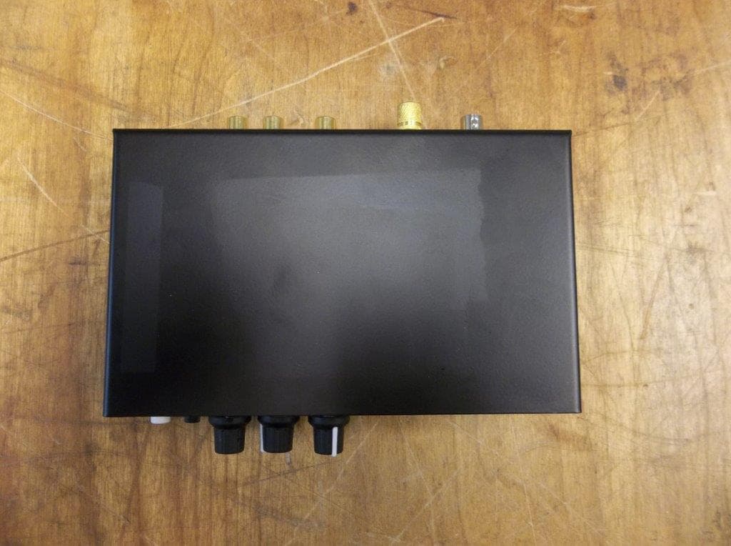
Click to zoom
Application Details
- Equipment Class
- DXX - Part 15 Low Power Communication Device Transmitter
- Date of Grant
- May 23, 2021
- Application Purpose
- Original Equipment
- Date of Application
- May 23, 2021
- Equipment Note
- Broadcast FM Band Transmitter
- Frequency Range
- 88.30000000 - 107.70000000
- Company
- Rolls Corporation
- Country
- United States
Documents & Files
Document Text
Text extracted from the exhibit documents filed with the FCC. Open a document above to read the original.
Users Manual
Digital FM Transmitter Rolls Corporation Salt Lake City, UT 5/21 www.rolls.com QUICK START OPERATION GUIDE HR70 FM TRANSMITTER + - 15 VDC ANTENNA FREQUENCY DNUP HR70 PWR DUCK MIC MIC LINE RELEASE TIME MIC AUX IN LINE INOUTPUT fast slow www.rolls.com LEVEL MUTE CLIP 12 1 - TALK OVER OFF 2 - PHANTOM POWER SENSITIVITY LEVEL ON 103.5MHz HR70 FCC ID: K48HR70 Rolls HR70 this device complies with Part 15 of the FCC Rules. Operation is subject to the following two conditions: (1) this device may not cause harmful interference, and (2) this device must accept any interference received, including interference that may cause undesired operation. SPECIFICATIONS Frequency Response: 20 Hz - 12.5 kHz Input Impedance: 100KΩ Unbalanced, 600Ω Balanced Indicators: Power LED and Clip LED Input/Output jacks: XLR balanced INPUT RCA unbalanced input and output Power: Rolls PS27s 12 - 15 VDC 500mA Antenna Jack: RP-SMA connector Antenna Impedance: 50Ω Tuning Range: 88.3 - 107.7 MHz Dimensions: 6.75"w x 4.25"d x 1.6"h Weight: 1.5 lbs Changes or modifications not expressly approved by Rolls Corp. could void the user's authority to operate the equipment. For Class A equipment: Note: This equipment has been tested and found to comply with the limits for a Class A digital device, pursuant to part 15 of the FCC Rules. These limits are designed to provide reasonable protection against harmful interference when the equipment is operated in a commercial environment. This equipment generates, uses, and can radiate radio frequency energy and, if not installed and used in accordance with the instruction manual, may cause harmful interference to radio commu- nications. Operation of this equipment in a residential area is likely to cause harmful interference in which case the user will be required to correct the interference at his own expense. INTRODUCTION Thank you for your purchase of the Rolls HR70 FM Digital Transmitter. This unit has been careful- ly designed and assembled to provide years of reliable FM transmission. Please read this manual carefully as it contains important information regarding the proper setup and operation of the HR70. Changes or modifications of any kind to the Rolls HR70 or its included antenna are not ap- proved or permitted in any way, and could void the user's authority to operate the equipment. INSPECTION Unpack and Inspect the package. Your HR70 was carefully packed at the factory in a protective carton. Nonetheless, be sure to examine the unit and the carton for any signs of damage that may have occurred during shipping. If obvious physical damage is noticed, contact the carrier immediately to make a damage claim. WARRANTY For complete Warranty information and registration, please visit our web site; www.rolls.com. Click on the REGISTER YOUR WARRANTY HERE line. DESCRIPTION FRONT PANEL HR70 FM TRANSMITTER + - 15 VDC ANTENNA FREQUENCY DNUP HR70 PWR DUCK MIC MIC LINE RELEASE TIME MIC AUX IN LINE INOUTPUT fast slow www.rolls.com LEVEL MUTE CLIP 12 1 - TALK OVER OFF 2 - PHANTOM POWER SENSITIVITY LEVEL ON 103.5MHz • DISPLAY: LCD display showing the active information relevant to the current operation of the HR70. • MIC/LINE: When pressed in, the gain of the XLR Mic In is reduced by 30 dB. • CLIP: LED for indication of when the circuit is over driven/clipping. • MUTE: When pressed unit will MUTE. • LEVEL: Adjusts the level of output. • FREQUENCY UP / DN: Selects the frequency that the HR70 is transmitting. • RELEASE TIME: Adjusts the amount of time for the “ducked” signal to return to its normal level. Counterclockwise; slow - Clockwise; fast. • MIC LEVEL: Adjusts the amount of gain for the Mic In circuit. • DUCK SENSITIVITY: The Threshold at which “ducking” begins. When the microphone level reaches the threshold, the signal present at the Line In jacks is reduced until the announcement is over, then the Line In signal returns to its previous level. A NOTE ON THE HR70 THRESHOLD SETTING, WITH THE SENSITIVITY CONTROL FULLY CLOCKWISE: If a signal is on the XLR input, the ducking will begin (the threshold is) at -30 dB when the Mic/Line switch is set to “Mic”, and 0 dB when the switch is set to “Line”. If the control signal is on the RCA input, ducking begins at -30 dB. DESCRIPTION CONTINUED HR70 DISPLAY -Channel Mhz - indicates Megahertz of FM transmission being sent - Mute indicator CONNECTION - Connect the Rolls supplied adapter to the VDC power jack of the HR70, then to an AC outlet with the proper voltage. - Connect the HR70 Left and Right line input to a mixer, or other audio device. WE RECOMMEND TURNING THE DUCK SENSITIVITY FULLY CLOCKWISE (ALL THE WAY UP) TO START. THIS IS THE HIGHEST SENSITIVITY AND MOST DUCKING AVAILABLE ON THE UNIT. OPERATION If you are using a condenser microphone, switch the Phantom Power on. Set the level of the music signal (Line In) for a comfortable level. Speak into the microphone and adjust the Mic Level for a comfortable level, then adjust the Sensitivity so that the music is muted when speaking with a normal voice. Set the Release Time control for the amount of time you wish for the Aux In signal to return to normal. REAR PANEL • 15VDC: USE THE ROLLS SUPPLIED PS27s ADAPTER ONLY!!! • Aux In: The Aux in is an input that will talk over the Line In (Main input) • Line in: This is the main line level input to the HR70. • Outputs: RCA stereo outputs. • Mic: XLR microphone input. • ANTENNA: Connects to the included RP-SMA FM transmitting antenna. HR70 FM TRANSMITTER + - 15 VDC ANTENNA FREQUENCY DNUP HR70 PWR DUCK MIC MIC LINE RELEASE TIME MIC AUX IN LINE INOUTPUT fast slow www.rolls.com LEVEL MUTE CLIP 12 1 - TALK OVER OFF 2 - PHANTOM POWER SENSITIVITY LEVEL ON 103.5MHz
Cover Letter(s)
5968 South 350 West Salt Lake City, UT 84107 (801) 263-9053 – FAX (801) 263-9068 www.rolls.com 5/10/2021 Federal Communications Commission 7435 Oakland Mills Road Columbia, MD 21046 Subject: Request for Permanent Confidentiality To whom it may concern: In accordance with 47CFR Section 0.457 and Section 0.459 pertaining to confidential material, we hereby request to hold permanently confidential all information contained within the below identified exhibits/document categories submitted pursuant to radio equipment certification requirements for FCC ID: K48HR70 1. Block Diagram 2. Operational Description 3. Schematics The above material contains trade secrets and proprietary information as specified by 47CFR 0.457(d) and technical data, which would customarily be guarded from competitors. The public disclosure of this information might be harmful to our company and provide unjustified benefits to our competitors. Sincerely, David DiFrancesco Exec VP Rolls Corporation
Cover Letter(s)
5968 South 350 West Salt Lake City, UT 84107 (801) 263-9053 – FAX (801) 263-9068 www.rolls.com 4/23/2021 To Whom It May Concern: We hereby delegate CKC Certification Services, LLC (CKC CS) power of attorney to act on our behalf in matters pertaining to certification of products. The actions of CKC CS shall be considered the same as our own. Sincerely, David DiFrancesco Exec VP
External Photos
F2P24290-C1A Page 1 of 3 2021-03-23 PHOTOGRAPHS: EXTERNAL Rolls Corporation - Model HR70 Order Number: F2P24290-C1A Client: Rolls Corporation Model: HR70 F2P24290-C1A Page 2 of 3 2021-03-23 Order Number: F2P24290-C1A Client: Rolls Corporation Model: HR70 F2P24290-C1A Page 3 of 3 2021-03-23
ID Label/Location Info
FCC ID: K48HR70 This device complies with Part 15 of the FCC Rules. Operation is subject to the following two conditions: (1) this device may not cause harmful interference, and (2) this device must accept any interference received, including interference that may cause undesired operation.
ID Label/Location Info
HR70 FM TRANSMITTER + - 15 VDC ANTENNA FREQUENCY DN UP HR70 PWR DUCK MIC MIC LINE RELEASE TIME MIC AUX IN LINE INOUTPUT fast slow www.rolls.com LEVEL MUTE CLIP 1 2 1 - TALK OVER OFF 2 - PHANTOM POWER SENSITIVITY LEVEL ON 103.5MHz FCC ID: K48HR70 This device complies with Part 15 of the FCC Rules. Operation is subject to the following two conditions: (1) this device may not cause harmful interference, and (2) this device must accept any interference received, including interference that may cause undesired operation.
Internal Photos
F2P24290-C1A Page 1 of 6 2021-03-23 PHOTOGRAPHS: INTERNAL Rolls Corporation - Model HR70 Order Number: F2P24290-C1A Client: Rolls Corporation Model: HR70 F2P24290-C1A Page 2 of 6 2021-03-23 Order Number: F2P24290-C1A Client: Rolls Corporation Model: HR70 F2P24290-C1A Page 3 of 6 2021-03-23 Order Number: F2P24290-C1A Client: Rolls Corporation Model: HR70 F2P24290-C1A Page 4 of 6 2021-03-23 Order Number: F2P24290-C1A Client: Rolls Corporation Model: HR70 F2P24290-C1A Page 5 of 6 2021-03-23 Order Number: F2P24290-C1A Client: Rolls Corporation Model: HR70 F2P24290-C1A Page 6 of 6 2021-03-23
Test Report
060818 Report Number: F2P24290-C1A-01E Page 1 of 41 Issue Date: 2021-05-12 F2 Labs 16740 Peters Road Middlefield, Ohio 44062 United States of America www.f2labs.com CERTIFICATION TEST REPORT Manufacturer: Rolls Corporation 5968 South 350 West Salt Lake City, Utah 84107 USA Applicant: Same as Above Product Name: Rolls HR70 FM Broadcast Transmitter Product Description: Low power FM broadcast transmitter for 200 ft or less radius use. With RCA and XLR inputs, recording outputs and ducking feature. Operating Voltage/Frequency: 12VDC Model: HR70 FCC ID: K48HR70 Testing Commenced: 2021-03-18 Testing Ended: 2021-05-12 Summary of Test Results: In Compliance, with Modifications The EUT complies with the EMC requirements when manufactured identically as the unit tested in this report, including any required modifications and/or manufacturer’s statement. Any changes to the design or build of this unit subsequent to this testing may deem it non-compliant. Standards: FCC Part 15 Subpart C, Section 15.239 – Operation in the band 88-108 MHz FCC Part 15 Subpart C, Section 15.215(c) – Additional provisions to the general radiated emission limitations FCC15.207 - Conducted Limits FCC Part 15 Subpart A, Section 15.31(e) – Measurement Standards Order Nos. F2P24290, F2P24290-C1A Applicant: Rolls Corporation Model: HR70 060818 Report Number: F2P24290-C1A-01E Page 2 of 41 Issue Date: 2021-05-12 Evaluation Conducted by: Ryan Littell, EMC Engineer Julius Chiller, EMC/Wireless Engineer Report Reviewed by: Ken Littell, Vice President of EMC F2 Labs F2 Labs F2 Labs 26501 Ridge Road 16740 Peters Road 8583 Zionsville Road Damascus, MD 20872 Middlefield, OH 44062 Indianapolis, IN 46268 Ph 301.253.4500 Ph 440.632.5541 Ph 317.610.0611 This test report may be reproduced in full; partial reproduction only may be made with the written consent of F2 Labs. The results in this report apply only to the equipment tested. Order Nos. F2P24290, F2P24290-C1A Applicant: Rolls Corporation Model: HR70 060818 Report Number: F2P24290-C1A-01E Page 3 of 41 Issue Date: 2021-05-12 TABLE OF CONTENTS Section Title Page 1 ADMINISTRATIVE INFORMATION 4 2 SUMMARY OF TEST RESULTS/MODIFICATIONS 7 3 TABLE OF MEASURED RESULTS 8 4 ENGINEERING STATEMENT 9 5 EUT INFORMATION AND DATA 10 6 LIST OF MEASUREMENT INSTRUMENTATION 11 7 OCCUPIED BANDWIDTH 12 8 FIELD STRENGTH OF EMISSIONS 19 9 VOLTAGE VARIATIONS 28 10 CONDUCTED EMISSIONS 31 11 PHOTOGRAPHS - TEST SETUPS 36 Order Nos. F2P24290, F2P24290-C1A Applicant: Rolls Corporation Model: HR70 060818 Report Number: F2P24290-C1A-01E Page 4 of 41 Issue Date: 2021-05-12 1 ADMINISTRATIVE INFORMATION 1.1 Measurement Location: F2 Labs in Middlefield, Ohio. Site description and attenuation data are on file with the FCC's Sampling and Measurement Branch at the FCC Laboratory in Columbia, MD. 1.2 Measurement Procedure: All measurements were performed according to the 2013 version of ANSI C63.10 and recommended FCC procedure of measurement of devices operating under Section 15.239. A list of the measurement equipment can be found in Section 6. Order Nos. F2P24290, F2P24290-C1A Applicant: Rolls Corporation Model: HR70 060818 Report Number: F2P24290-C1A-01E Page 5 of 41 Issue Date: 2021-05-12 1.3 Uncertainty Budget: The uncertainty in EMC measurements arises from several factors which affect the results, some associated with environmental conditions in the measurement room, the test equipment being used, and the measurement techniques adopted. The measurement uncertainty budgets detailed below are calculated from the test and calibration data and are expressed with a 95% confidence factor using a coverage factor of k=2. The Uncertainty for a laboratory is referred to as Ulab. For Radiated and Conducted Emissions, the Expanded Uncertainty is compared to the Ucispr values to determine if a specific margin is required to deem compliance. Ulab Ucispr If Ulab is less than or equal to Ucispr, then: • compliance is deemed to occur if no measured disturbance exceeds the disturbance limit; • non-compliance is deemed to occur if any measured disturbance exceeds the disturbance limit. If Ulab is greater than Ucispr in table 1, then: • compliance is deemed to occur if no measured disturbance, increased by (Ulab – Ucispr), exceeds the disturbance limit; • non-compliance is deemed to occur if any measured disturbance, increased by (Ulab – Ucispr), exceeds the disturbance limit. Note: Only measurements listed in the tables above that relate to tests included in this Test Report are applicable. Measurement Range Combined Uncertainty Expanded Uncertainty Radiated Emissions <1 GHz @ 3m 2.54 5.07dB Radiated Emissions <1 GHz @ 10m 2.55 5.09dB Radiated Emissions 1 GHz to 2.7 GHz 1.81 3.62dB Radiated Emissions 2.7 GHz to 18 GHz 1.55 3.10dB AC Power Line Conducted Emissions, 150kHz to 30 MHz 1.38 2.76dB AC Power Line Conducted Emissions, 9kHz to 150kHz 1.66 3.32dB Measurement Range Expanded Uncertainty Radiated Emissions <1 GHz @ 3m 5.2dB Radiated Emissions <1 GHz @ 10m 5.2dB Radiated Emissions 1 GHz to 2.7 GHz Under Consideration Radiated Emissions 2.7 GHz to 18 GHz Under Consideration AC Power Line Conducted Emissions, 150kHz to 30 MHz 3.6dB AC Power Line Conducted Emissions, 9kHz to 150kHz 4.0dB Order Nos. F2P24290, F2P24290-C1A Applicant: Rolls Corporation Model: HR70 060818 Report Number: F2P24290-C1A-01E Page 6 of 41 Issue Date: 2021-05-12 1.4 Document History: Document Number Description Issue Date Approved By F2P24290-C1A-01E First Issue 2021-05-12 K. Littell Order Nos. F2P24290, F2P24290-C1A Applicant: Rolls Corporation Model: HR70 060818 Report Number: F2P24290-C1A-01E Page 7 of 41 Issue Date: 2021-05-12 2 SUMMARY OF TEST RESULTS Test Name Standard(s) Results -20dB Occupied Bandwidth CFR 47 Part 15.215(a) Complies Field Strength of Emissions CFR 47 Part 15.239(b) Complies* Variation of the Input Power CFR 47 Part 15.31(e) Complies Conducted Emissions CFR 47 Part 15.207(a) Complies *Complies with modifications noted below. Note:…
Text truncated - open the document above for the full version.
Test Setup Photos
F2P24290-C1A Page 1 of 6 2021-05-12 PHOTOGRAPHS: TEST SETUP Rolls Corporation - Model HR70 Radiated Spurious Emissions: 0.009 MHz to 0.15 MHz Radiated Spurious Emissions: 30 MHz to 1000 MHz Order Number: F2P24290-C1A Client: Rolls Corporation Model: HR70 F2P24290-C1A Page 2 of 6 2021-05-12 Radiated Spurious Emissions: 1 GHz to 3 GHz Order Number: F2P24290-C1A Client: Rolls Corporation Model: HR70 F2P24290-C1A Page 3 of 6 2021-05-12 Occupied Bandwidth Order Number: F2P24290-C1A Client: Rolls Corporation Model: HR70 F2P24290-C1A Page 4 of 6 2021-05-12 Field Strength of Emissions Order Number: F2P24290-C1A Client: Rolls Corporation Model: HR70 F2P24290-C1A Page 5 of 6 2021-05-12 Voltage Variations Order Number: F2P24290-C1A Client: Rolls Corporation Model: HR70 F2P24290-C1A Page 6 of 6 2021-05-12 Conducted Emissions
Contact Information
Applicant
David DiFrancesco(Executive Vice President)
Test Firm
F2 LabsWendy Fuster
Technical Specifications
| # | Rule Parts | Frequency Range | Power Output |
|---|---|---|---|
| 1 | 15C | 88.3 MHz - 107.7 MHz | - |