K4BAP01
Wi Lan Inc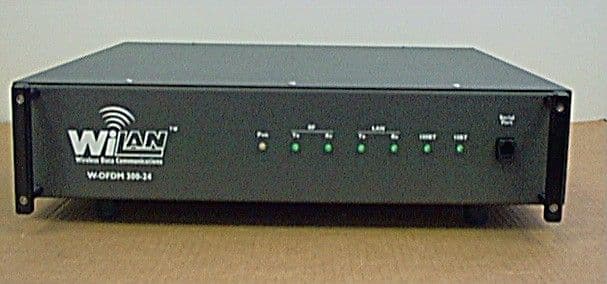
Click to zoom
Application Details
- Equipment Class
- DTS - Digital Transmission System
- Date of Grant
- Jun 03, 2001
- Application Purpose
- Original Equipment
- Date of Application
- Feb 16, 2000
- Frequency Range
- 2415.00000000 - 2465.00000000
- Company
- Wi Lan Inc
- Country
- Canada
Documents & Files
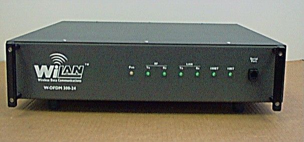
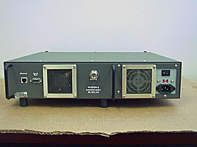
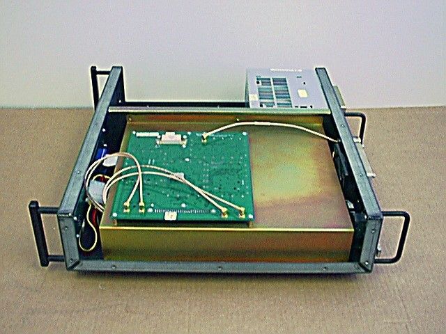
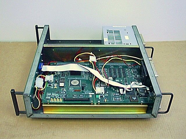
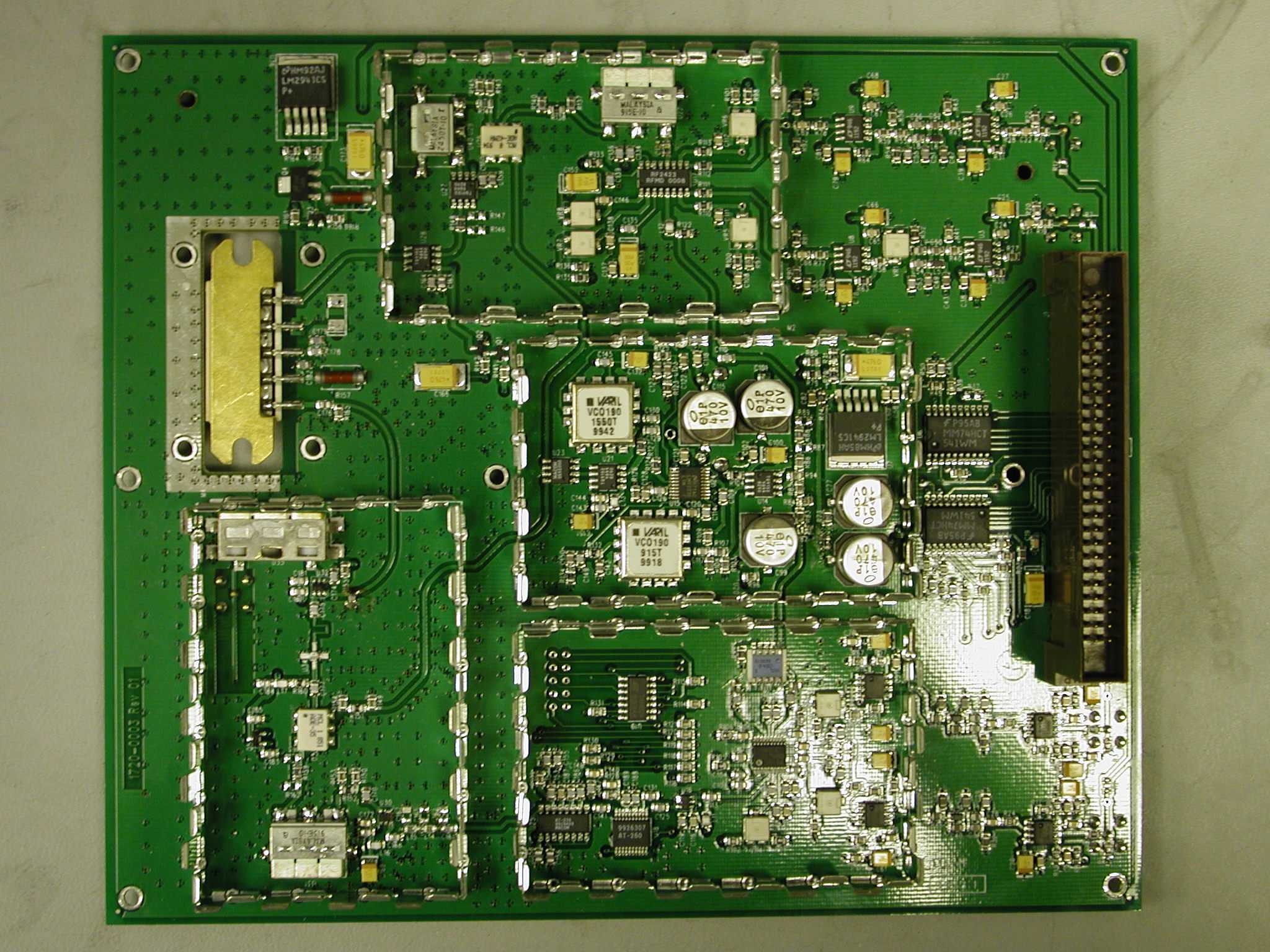
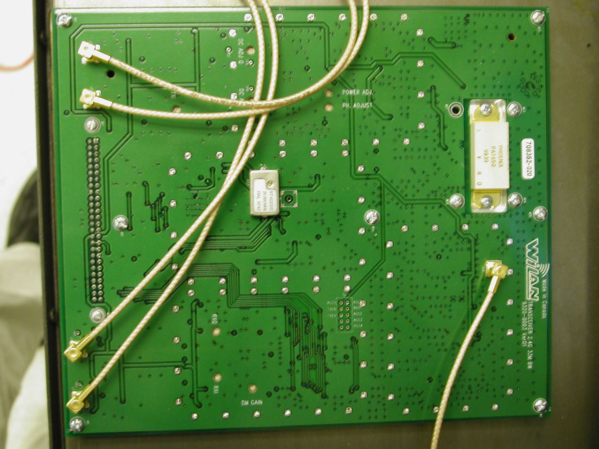
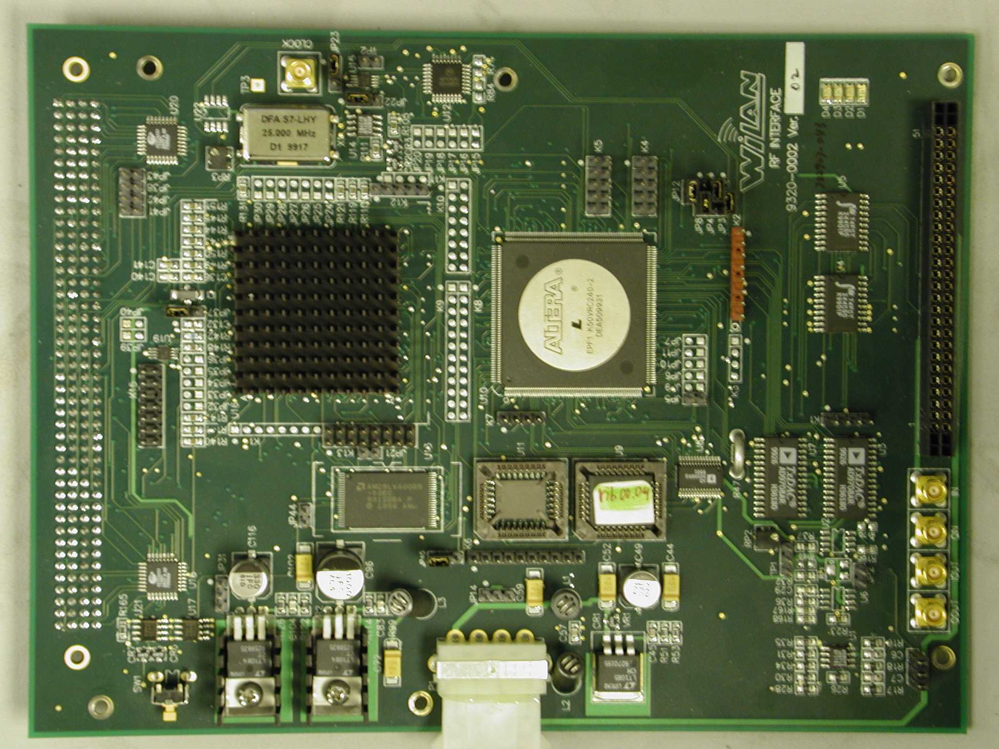
Document Text
Text extracted from the exhibit documents filed with the FCC. Open a document above to read the original.
Users Manual
Version 1.1 - 01/04/00i Contents Welcome ..................................................................... 1 Overview of the I.WiLL™ 300-24 Access Point ......................................... 1 About this Guide ........................................................................................ 1 What’s in this Guide ................................................................................... 1 Conventions Used in this Guide ................................................................. 2 Customer Support ...................................................................................... 3 Contacting Customer Support .............................................................. 3 Get Started .................................................................. 5 Overview .................................................................................................... 5 Understanding the Front and Back Panels ................................................ 5 The Front Panel .................................................................................... 5 The Back Panel .................................................................................... 7 Completing Pre-Installation ...................................... 9 Overview .................................................................................................... 9 Installation Requirements .......................................................................... 9 Planning the Physical Layout ................................................................... 10 Determining the Physical Distance Between Sites ............................. 10 Working with Antennas ....................................................................... 10 Determining Cable Requirements ...................................................... 11 Working with Fade Margins ................................................................ 11 Assessing the Weatherproofing Requirements .................................. 11 Pre-configuring the Stations ..................................................................... 11 Pre-configuring Stations ..................................................................... 11 Pre-configuring the Polling List ........................................................... 14 Bench Testing the 300-24 ........................................................................ 16 Determining the RF Link ......................................... 17 Overview .................................................................................................. 17 Calculating the Link Budget ..................................................................... 17 Link Budget Variables ......................................................................... 18 Working with System Gain ................................................................. 18 Contents iiVersion 1.1 - 01/04/00 Calculating ERP (Effective Radiated Power) ..................................... 19 Working with Antenna Gain ............................................................... 19 Calculating Propagation Loss ............................................................ 20 Calculating Cable Loss ...................................................................... 21 Calculating Path Loss ........................................................................ 22 Link Budget Example .............................................................................. 23 Verifying a Link Budget ........................................................................... 24 Reviewing the Link Statistics ............................................................. 24 Installing Base and Remote Stations ..................... 27 Overview ................................................................................................. 27 Installing the Antenna .............................................................................. 27 Powering Up the Units ............................................................................. 27 Verifying the RF Port .......................................................................... 28 Fine-tuning Antennas ......................................................................... 29 Completing the Installation Connections ............................................ 29 Installing the Units on a Rack .................................................................. 30 Configuring Using the Menus ................................. 31 Overview ................................................................................................. 31 Navigating the Configuration Menus ....................................................... 31 Accessing the Menus ......................................................................... 31 Using the Console .............................................................................. 32 Using Telnet ....................................................................................... 33 Exiting the Configuration Menus ........................................................ 34 Viewing System Information .................................................................... 35 Viewing System Revision Information ................................................ 35 Viewing System Software ROM Images ............................................ 36 Viewing Current System Status ......................................................... 37 Viewing the MAC Layer Statistics ...................................................... 39 Setting the System Security .................................................................... 42 Setting Access Types ........................................................................ 42 Setting Community Names ................................................................ 43 Setting Passwords ............................................................................. 44 Setting Automatic Timeouts ......…
Text truncated - open the document above for the full version.
Users Manual
MAY 2001 1 May 2001 Change to I.WiLL 300-24 Access Point Manual Please replace pages 19—20 of the I.WiLL 300-24 Access Point manual (Version 1.1 - 02/00) with the attached replacement page. Information about EIRP has been clarified and corrected on the replacement page. Calculating the Link Budget Version 1.1 - 05/0119 Calculating EIRP (Effective Isotropic Radiated Power) EIRP is the power radiating from an antenna taking into account the output power from the transmitter, the connector and cable losses, and the antenna gain. Because many antennas can provide a directional gain, the effective radiated power can increase. Losses, such as cable losses can subtract from this amount. You calculate the EIRP as follows: Note: All EIRP work must be completed by a professional installer. Working with Antenna Gain To ensure the best range and interference suppression, the external antenna should be directional, focusing the radio energy in one direction (toward the other end of the link). The direction can be azmuthal or a horizontal radiation angle. A directional antenna focuses the RF energy to the intended station rather than omni-directionally. This reduces interference from other systems that are operating at the same frequency. Note: In some situations, you may want to use an omni-directional antenna in your system design. For example, you would use an omni-directional antenna for a base station with remote sites situated in a 360... path around it. When you select an antenna, pay particular attention to the gain specification. When you select an antenna for a remote station, select an antenna with a gain that provides at least 13dB Fade Margin. Antenna gain is specified in either dBi or dBd. When an antenna is specified in dBd, add 2.14dB to the value to convert it to dBi. Note: All antenna gain work must be completed by a professional installer. Formula:EIRP = Tx Power (dBm) - Cable Losses (dBm) - Connector Losses (dBm) + Antenna Gain (dB) Note:The FCC regulatory body has set the peak EIRP limit to 400 mW for multipoint and fixed point-to-point applications per FCC 01-158 with a peak power output of 100 mW. Only the antenna with which the equipment is authorized may be used per FCC 47 CFR 15.204(c). Industry Canada RSS-139, Annex B specifies the maximum transmitter output at +30dBm, with a maximum EIRP (Equivalent Isotropically Radiated Power) at +36dBm for multi-point configurations and a maximum EIRP of +53dBm only for licensed point-to-point applications. In accordance with ETS 300-328 for 2.4GHz RLANs, the maximum EIRP shall not exceed +20dBm, with a maximum SPD (Spectral Power Density) not exceeding +10dBm/MHz. Confirmation is required with the relevant European national radio communications local authority for deviations from this specification. Unlike the Tx output power of the devices, EIRP is subject to both antenna gain and cable losses. Determining the RF Link 20Version 1.1 - 05/01 Calculating Propagation Loss The propagation loss is the attenuation (reduction) in RF signal energy as it travels through space. In most wireless systems, losses through space are the major contributor to signal attenuation. When you know the intended installation locations of the base and remote stations, determine the physical line of sight distance and then calculate the RF attenuation as follows: Note: All propagation loss work must be completed by a professional installer. Working with the Fresnel Zone It is essential to locate your antennas at maximum above-ground height to ensure the most effective and reliable link. Achieving maximum above-ground antenna height means that: ¥all ground-based obstructions are cleared from the line-of-sight path ¥the Fresnel Zone is clear of obstructions Formula:Attenuation (dB) = 100dB + 20log(d km ) where: d km = Distance in Kilometers 100dB = Pathloss Constant Note:The FCC regulatory body has set the peak EIRP limit to 400 mW for multipoint and fixed point-to-point applications per FCC 01-158 with a peak power output of 100 mW. Only the antenna with which the equipment is authorized may be used per FCC 47 CFR 15.204(c). Industry Canada RSS-139, Annex B specifies the maximum transmitter output at +30dBm, with a maximum EIRP (Equivalent Isotropically Radiated Power) at +36dBm for multi-point configurations and a maximum EIRP of +53dBm only for licensed point-to-point applications. Industry Canada RSS-139, Annex B specifies the maximum transmitter output at +30dBm, with a maximum EIRP (Equivalent Isotropically Radiated Power) at +36dBm for multi-point configurations and a maximum EIRP of +53dBm only for licensed point-to-point applications. In accordance with ETS 300-328 for 2.4GHz RLANs, the maximum EIRP shall not exceed +20dBm, with a maximum SPD (Spectral Power Density) not exceeding +10dBm/MHz. Confirmation is required with the relevant European national radiocommunications local authority for deviations from this specification.
Attestation Statements
May 29, 2001 Mr. Joe Dichoso Federal Communications Commission Office of Engineering & Technology Equipment Authorization Branch 7435 Oakland Mills Road Columbia, Md. U.S.A.21046 Re: FCC ID K4BAP01 Reply to Correspondence Reference Number 19280 Item 3) Justification of Professional Installation Dear Mr. Dichoso, This is to confirm that the marketing or sale of the I.WiLL 300-24 AP product will be restricted to authorized dealers and will not be offered for sale to the general public, through retail outlets or by mail order. The high-end price range of the product makes it prohibitive for general public sale. The application for use is for commercial and industrial deployment and it is not intended for use by the general public. As noted in the user manual, this equipment requires professional installation by experienced radio personnel. These must be knowledgeable about the radiated power requirements and restrictions under FCC 47 CFR Part 15 rules for intentional radiators. Operation, configuration and optimization of the equipment requires special authorized password protected access, as well as, knowledge of RF system link budgets and understanding of field strength and radio signal quality indicators. The entire user interface is suited to personnel who are technically competent in its use and training is recommended and available to augment proper use and installation. I trust this satisfies your query with respect to professional installation. Yours truly, Eric Godberson – Manager, Hardware Development & Technical Advisor, Regulatory Wi-LAN, Inc. 300, 801 Manning Road NE Calgary, AB. CanadaT2E 8J5 Tel: (403) 207-6486 Email: [email protected]
Block Diagram
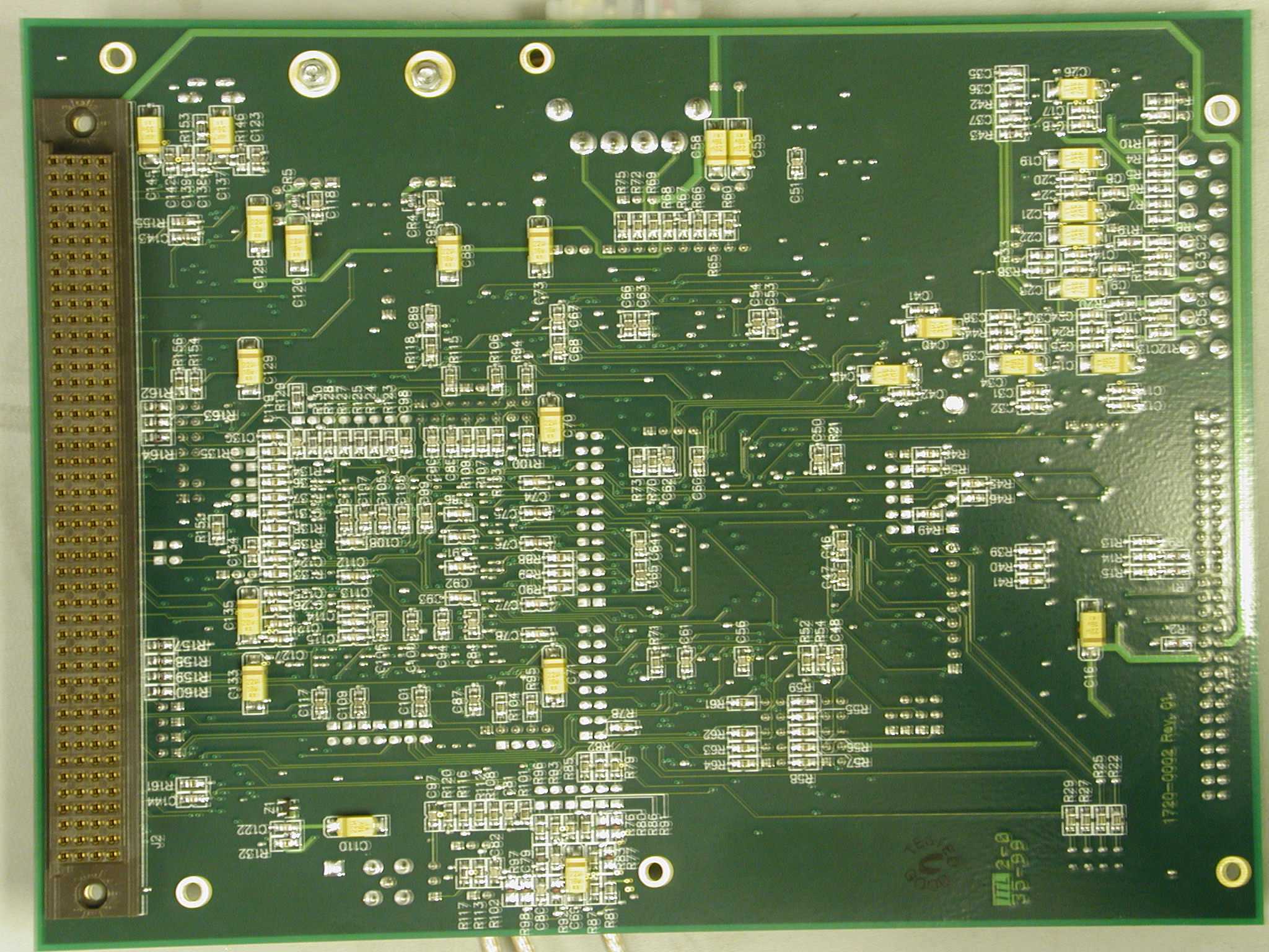
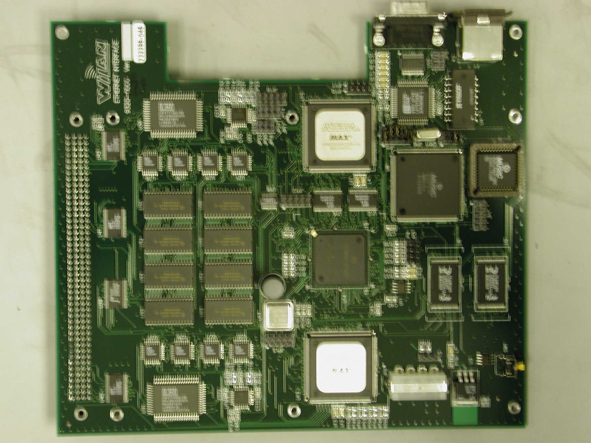
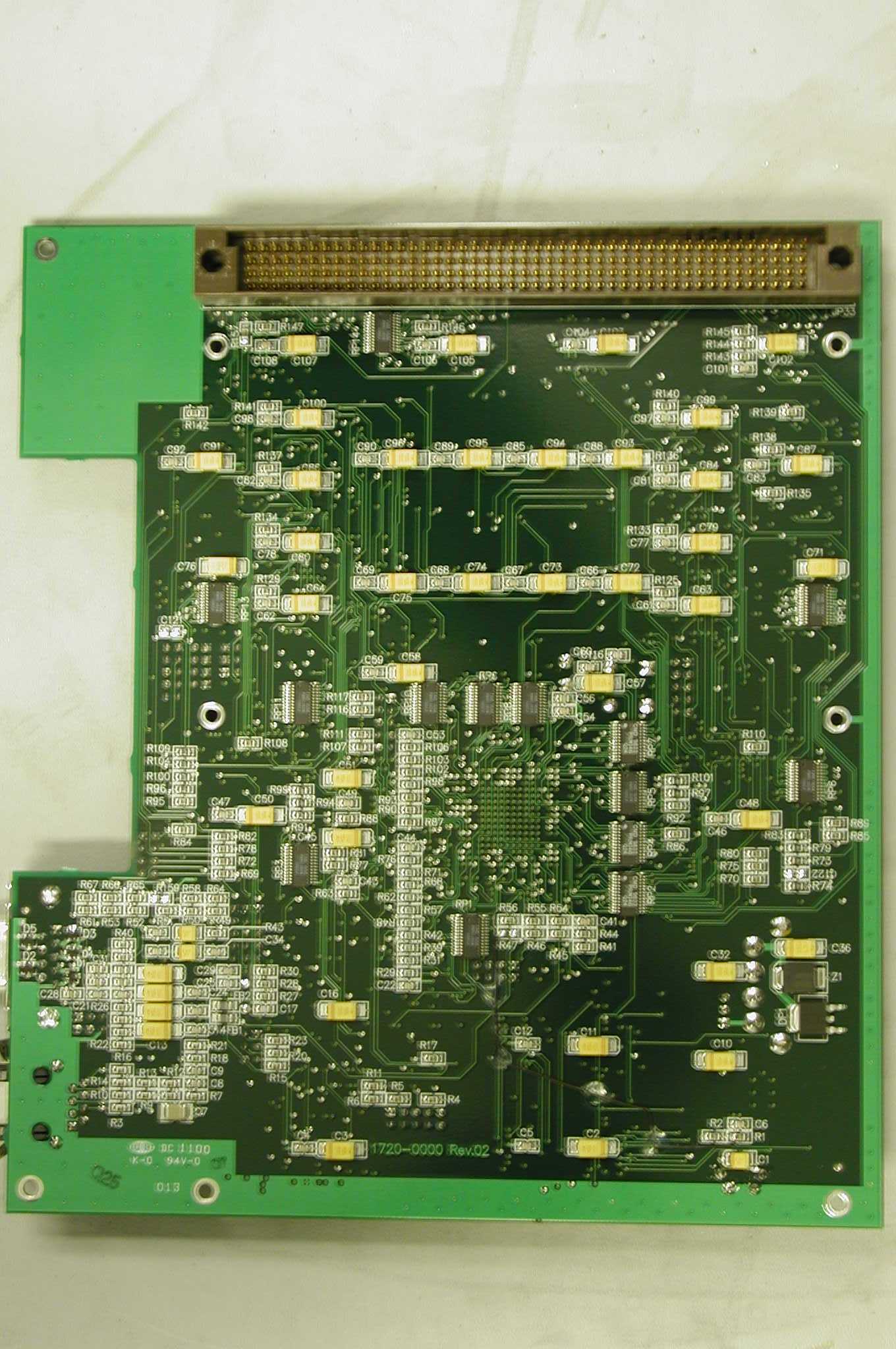
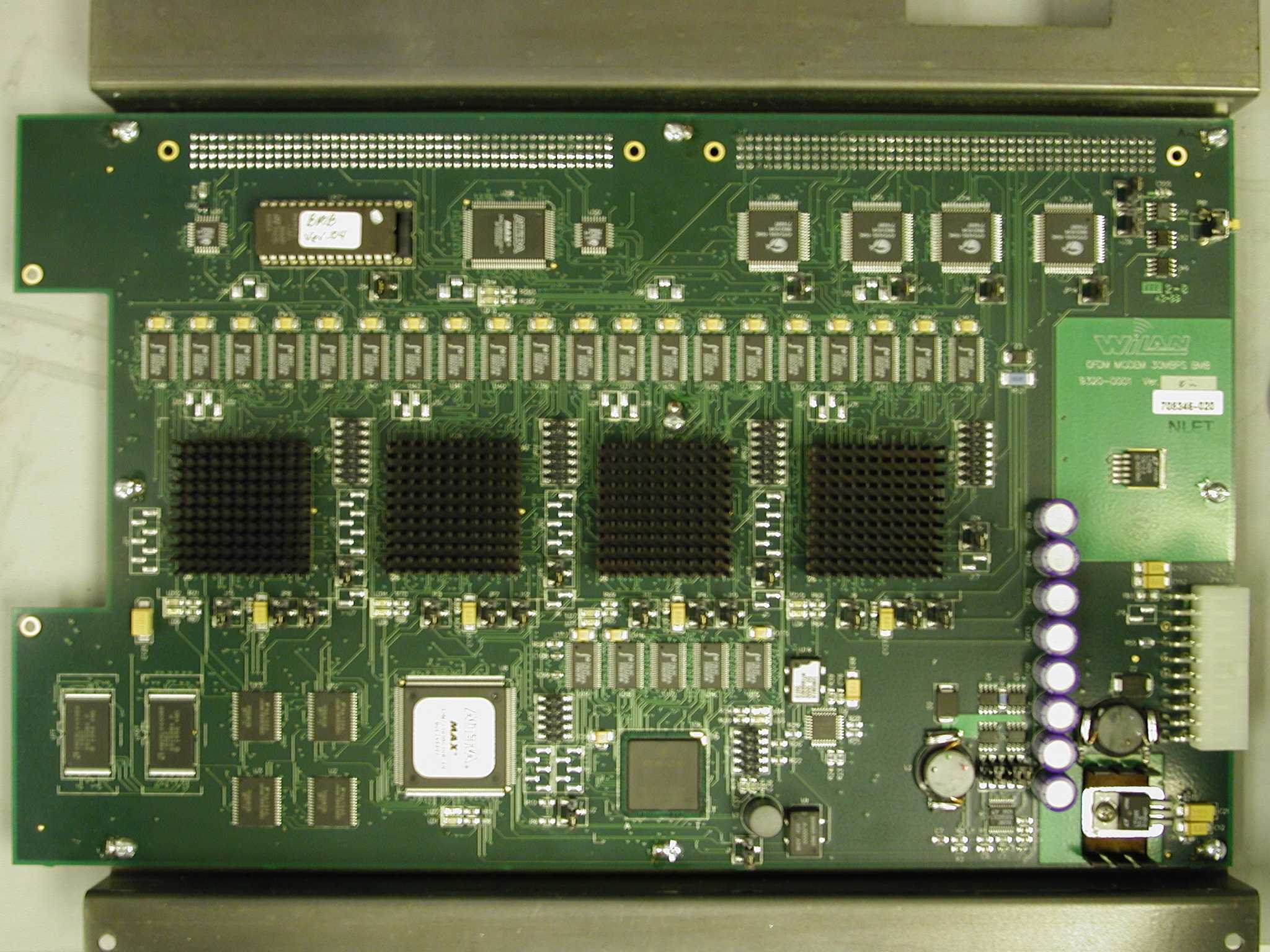
W-OFDM 30024 Overview Draft 1 INTRODUCTION The W-OFDM 30024 is a wireless Ethernet transceiver using Wide-band Orthogonal Frequency Division Multiplexing (W-OFDM) modulation/demodulation technology. The W-OFDM transceiver transfers data in half-duplex mode at a rate of 30 Mbps within a 25 MHz bandwidth in the 2.4 GHz Industrial, Scientific and Medical (ISM) band. Figure 1.1 shows the main functional blocks of a W-OFDM 30024 system. It consists four main boards, a Wire Interface Board (WIB), a Baseband Modulation Board (BMB), an RF Interface Board (RFIB), and an RF Board. This document delineates these major function boards. W-OFDM 30024 Overview Draft 2 WIB Fast Ethernet Interface Forward Error CorrectionSystem Maintenance Network Data Management BMB DSPWire-side Buffer Arbitration ControllerRF-side Buffer DB 9 RFIB DSP RF Sampling LogicData Conversion RF Board IF Conversion RF FrontSynthesizer Carrier Modulation/ Demodulation RJ 45 Figure 1 W-OFDM 30024 Block Diagram W-OFDM 30024 Overview Draft 3 FUNCTIONAL DESCRIPTION Wire Interface Board The Wire Interface Board connects the W-OFDM 30024 system to a data network. The board serves four major purposes, a Fast Ethernet Interface, network data management, system maintenance, and Forward Error Correction (FEC). The Fast Ethernet Interface on the WIB, which complies with the IEEE 802.3 Standard, can operate at a maximum data rate of 100 Mbps with auto-negotiation capability. The WIB is also responsible to control the data traffics passing through the system. Packet filtering is done on the data coming from the Ethernet network using Content Addressable Memory (CAM) to prevent local traffics from overflowing the wireless link. In addition, bandwidth management is implemented on the WIB to maintain the efficiency of the system. The transmitted data are encoded with a Forward Error Correction (FEC) scheme, and decoded on the receiving unit accordingly on the WIB. Due to the nature of the errors in OFDM symbols in a multi-path environment, Reed-Solomon Coding, one of the FEC schemes, is the best candidate for the W-OFDM 30024 system. There is a system maintenance port on the WIB. The major functions of the port are network statistics collection, network system configuration, and system maintenance. Baseband Modulation Board The Baseband Modulation Board is the heart of a W-OFDM 30024 system. The board modulates the transmitted data and demodulates the received data respectively according to the OFDM algorithm. It includes four blocks, Wire-side Buffer, DSP, Arbitration Controller and RF-side Buffer. The Wire-side Buffer is namely the storage of the transferred data between the WIB and the BMB. The requirement for the buffer on each direction is to hold minimum of two super-frames to increase the efficiency of data transferring – read from and write to the buffer simultaneously. The DSP block is responsible to modulate or demodulate the transferred data. On the transmitting side, the OFDM scheme is performed on the complex data generated by 16 QAM, whereas the exact reverse operation is performed on the receiving side. Channel estimation and phase randomization are also implemented in the DSP block to overcome the problems of high peak-to-average signal amplitude and fading due to multi-path effects. To achieve 30 Mbps data throughput, at least four DSPs are required based on the calculation of 9 Mbps per DSP, including arbitration latency. The TMS320C6201 of Texas Instrument running at 200 MHz is used in such calculation. W-OFDM 30024 Overview Draft 4 The function of the Arbitration Controller is to orchestrate the DSPs. Since the arbitration scheme can directly impact the throughput of the system, an effective method is needed to maintain a desired throughput. Similar to the Wire-side Buffer, the RF-side Buffer is used to store transferred data between the RFIB and the BMB. The buffers in each direction should be large enough to contain one modulated super-frame. Assuming a modulated super-frame is 0.5 ms long, with 25 M Samples/s, and 2 bytes (I and Q) per sample, the minimum size of the buffers in each direction therefore is 25 Kbytes. RF Interface Board The RF Interface Board converts baseband signals to analog ones or vise versa between the BMB and RF board. The RFIB, in addition, manages the automatic gain control, signal synchronization and wireless link protocol. Three main components, RF Sampling Logic, DSP, Data Conversion are on the RFIB. The RF Sampling Logic interfaces the A/D Conversion block and the D/A Conversion block on the RFIB with the BMB’s RF-side Buffer. Since the system is half-duplex operation, coordination of A/D conversion and D/A conversion is necessary. Automatic gain control and signal synchronization are also implemented in the block when a system is used as a receiver. The DSP serves two purposes, wireless link protocol and signal synchronization. Since the W-OFDM 30024 is designed for a point to multi-point network, a wireless link protocol is required to arbitrate the network traffics among stations. Prior to the actual OFDM data, a Direct Spread Spectrum Sequence (DSSS) header is generated by the DSP to obtain signal synchronization between a transmitter and a receiver. Data Conversion performs two functions, A/D conversion and D/A conversion. A/D converts the transmitted digital signal to analog one and output it to the RF board, while D/A converts the received analog signal to digital one. Eight-bit data bus is used at all digital channel. RF Board The RF board is the wireless link end of a W-OFDM 30024 system. As a transmitter, the board modulates the baseband signal from the RFIB to a desired frequency band, 2.4 GHz ISM band in this application. Reverse operation is performed when a system acts as a receiver. Four major blocks, Carrier Modulation/Demodulation, IF Conversion, RF Front, and Synthesizer are on the RF board. Carrier Modulation/Demodulation block is responsible to modulate the baseband signals,…
Text truncated - open the document above for the full version.
Cover Letter(s)
February 16, 2000 FCC, Laboratory Division Equipment Authorization Branch 7435 Oakland Mills Road Columbia, Md. U.S.A.21046 Re: Request for Confidentiality on I.Will 300-24 Access Point - Schematic Materials Ref. FCC ID: K4BAP01 Dear Sir/Madam, Please accept this request, as provided by Section 0.459, that the following materials or documents submitted as part of the Certification application for the I.Will 300-24 Access Point be treated as confidential, never to be disclosed by the Commission, due to the fact that such materials contain trade secrets and proprietary technical information, which is the sole and exclusive property of Wi-LAN, Inc. of 300, 801 Manning Road NE, Calgary, Canada, T2E 8J5: 1. Wi-LAN Schematic: Drawing No.: 9320-0000, Title: Ethernet Interface 10/100BASET, 15 Sheets 2. Wi-LAN Schematic: Drawing No.: 9320-0001, Title: OFDM MODEM 30MBPS, 28 Sheets 3. Wi-LAN Schematic: Drawing No.: 9320-0002, Title: RF Interface 30 MBPS, 13 Sheets 4. Wi-LAN Schematic: Drawing No.: 9320-0003, Title: TRANSCEIVER 2.4G 33M BW, 7 Sheets It is obvious that the above listed materials meet the trade secret and technical data requirements specified in Section 0.457(d), since possession of this material would allow another party technical capability in be ing able to reproduce the product and competitive advantage in understanding the products design. Wi-LAN has taken action to prevent unauthorized disclosure by providing on each and every sheet of the afore-mentioned schematic drawing materials a PROPRIETARY NOTE. Respectfully yours, Eric Godberson - Manager, Product Delivery Wi- LAN, Inc. 300, 801 Manning Rd. NE Calgary, AB. CanadaT2E 8J5 Telephone: 403-273-9133Fax.: 403-273-5100 E-Mail: [email protected]
RF Exposure Info
Maximum Permissible Exposure (MPE) Statement of Compliance FCC MPE Statement of Compliance Product Model: I.WiLL 300-24 AP Product Part Number: 9220-0000 Peak Transmitter Output Power: 100mW (20dBm) Center Channel Frequency Range: 2415-2465MHz Transmitter Type Classification: __Portable X _Mobile (Mobile apparatus defined as being at least 20cm away from human body) Equipment Exemption:__ Yes X_ No (Mobile above 1.5GHz < 3W ERP) Power Density Calculation for Small Antenna, RF Exposure: Max. Antenna Gain: 2.14dBi, Dipole Far-field ( /2 ):W = P T G/4 r² = (100mW)(1.64)/4 (0.23m)² = 0.247W/m² (@ 23cm) 47 CFR §1.1310 General Public/Uncontrolled Exposure Limit (1.5-100GHz): 1mW/cm² (10W/m²) The aforementioned equipment and antenna has been evaluated and found to comply with the MPE limits, as specified in 47 CFR §1.1310 for the general public and uncontrolled conditions, using the guidelines found in FCC OET Bulletin 65. ________________________________________ Date: May 16, 2001 Eric Godberson – Technical Advisor, Regulatory Wi-LAN, Inc. 300, 801 Manning Rd. NE Calgary, AB. T2E 8J5
Test Report
Master: ktlPT15CDST Date: November 5, 1999 KTL Test Report:9R02023 Applicant:WiLAN Inc. 300-801 Manning Road, NE Calgary, Alberta T2E 8J5 Equipment Under Test:OFDM 300-24 (E.U.T.) In Accordance With:FCC Part 15, Subpart C Direct Sequence Transmitters 2400-2483.5 MHz Tested By:KTL Ottawa Inc. 3325 River Road, R.R. 5 Ottawa, Ontario K1V 1H2 Authorized By: K. Carr, Technologist Date: Total Number of Pages:34 KTL OttawaFCC PART 15, SUBPART C DIRECT SEQUENCE TRANSMITTERS PROJECT NO.: 9R02023 EQUIPMENT: OFDM 300-24 Page 2 of 31 Table Of Contents Section 1. Summary Of Test Results.....................................................................................3 Section 2. General Equipment Specification........................................................................5 Section 3. Powerline Conducted Emissions..........................................................................7 Section 4. Occupied Bandwidth..........................................................................................11 Section 5. Peak Power Output.............................................................................................16 Section 6. Spurious Emissions (Antenna Conducted)........................................................18 Section 7. Spurious Emissions (Radiated)..........................................................................22 Section 8. Transmitter Power Density................................................................................26 Section 9. Processing Gain...................................................................................................30 Section 10.Test Equipment List............................................................................................31 Annex A Block Diagrams...................................................................................................A1 KTL OttawaFCC PART 15, SUBPART C DIRECT SEQUENCE TRANSMITTERS PROJECT NO.: 9R02023 EQUIPMENT: OFDM 300-24 Page 3 of 31 Section 1.Summary Of Test Results Manufacturer:WiLAN Inc. Model No.:W-OFDM 300-24 Serial No.:W700007 Date Received In Laboratory: December 2, 1999 KTL Identification No.: Item #1 General:All measurements are traceable to national standards. These tests were conducted on a sample of the equipment for the purpose of demonstrating compliance with FCC Part 15, Subpart C, Paragraph 15.247 for Direct Sequence Spread Spectrum devices. New SubmissionProduction Unit Class II Permissive ChangePre-Production Unit Equipment CodeFamily Listing THIS TEST REPORT RELATES ONLY TO THE ITEM(S) TESTED. THE FOLLOWING DEVIATIONS FROM, ADDITIONS TO, OR EXCLUSIONS FROM THE TEST SPECIFICATIONS HAVE BEEN MADE. See “ Summary of Test Data”. NVLAP LAB CODE: 100351-0 TESTED BY: _____________________________________ DATE: ___________________ Glen Westwell, Technologist KTL Ottawa Inc. authorizes the above named company to reproduce this report provided it is reproduced in its entirety and for use by the company’s employees only. Any use which a third party makes of this report, or any reliance on or decisions to be made based on it, are the responsibility of such third parties. KTL Ottawa Inc. accepts no responsibility for damages, if any, suffered by any third party as a result of decisions made or actions based on this report. This report applies only to the items tested. KTL OttawaFCC PART 15, SUBPART C DIRECT SEQUENCE TRANSMITTERS PROJECT NO.: 9R02023 EQUIPMENT: OFDM 300-24 Page 4 of 31 Summary Of Test Data NAME OF TESTPARA. NO.SPEC.RESULT Powerline Conducted Emissions15.207 (a) 48 dBμV Complies Occupied Bandwidth15.247 (a)(2) ≥500 kHz Complies Peak Power Output15.247 (b)1 wattComplies Spurious Emissions (Antenna Conducted) 15.247 (c)-20 dBcComplies Spurious Emissions (Radiated) 15.247 (c)Table 15.209 (a) Complies Transmitter Power Density15.247 (d) ≤ +8 dBm Complies Processing Gain15.247 (e) ≥ 10 dB To Be Supplied By Customer Footnotes For N/A’s: Test Conditions: IndoorTemperature:20 °C Humidity:25 % OutdoorTemperature:5.5 °C Humidity:31 % KTL OttawaFCC PART 15, SUBPART C DIRECT SEQUENCE TRANSMITTERS PROJECT NO.: 9R02023 EQUIPMENT: OFDM 300-24 Page 5 of 31 Section 2.General Equipment Specification Transmitter Power Input: 120 VAC/60 Hz, 240 VAC/50 Hz Frequency Range: 2415 – 2465 MHz Tunable Bands: 1 Number of Channels: 3 6 dB Bandwidth: 14.3 MHz Type of Modulation Combined Direct Sequence Spread Spectrum & Wide Band Orthogonal Frequency Division Multiplexing (W-OFDM) Data Rate: 30 Mbps Internal / External Data Source: Internal Emissions Designator: 23M2F1D Output Impedance: 50 ohms RF Power Output (Rated): 20 dBm Power Output Adjustment Capability: None KTL OttawaFCC PART 15, SUBPART C DIRECT SEQUENCE TRANSMITTERS PROJECT NO.: 9R02023 EQUIPMENT: OFDM 300-24 Page 6 of 31 Theory of Operation The I.WILL 300-24 Access Point (300-24) is the first Wi-LAN product based on the Wide-Band Orthogonal Frequency Division Multiplexing (W-OFMD) technology. With a peak data rate of 30 Mbps in 25 MHz of bandwidth. The Dynamic Time Allocation technique allocates variable time slots to busy stations when needed. Valuable bandwidth is not wasted allocated time to idle stations. The 300-24 operates in the 2.4 – 2.4835 GHz license-exempt ISM band allowing you to provide wireless networking connectivity at a fraction of the wire, cable or fibre networking costs. The user can manager, configure and monitor the entire wireless network through the RS-232 management port, SNMP or telnet. The I.WILL 300-24 Access Point (300-24) is a multi-point product that allows wireless connection of remote computers or LAN segments at signaling rates up to 30 Mbps. The unit is self-contained and easy to use. You do not need installation disks or software drivers to get started. The user connects the 300-24 to each LAN segment. W-OFDM Wide-band Orthogonal Frequency Division Multiplexing. A transmission scheme that encodes data inside a radio frequency signal. OFDM sends a high-speed signal concurrently on di…
Text truncated - open the document above for the full version.
Test Report
____________________________________________________________________________________________ Technology that goes the Distance Wi-LAN Inc. 300-801 Manning Rd. NE Calgary, Alberta, T2E 8J5 Phone: (403) 273-9133 Fax: (403) 273-5100 Wi-LAN inc. Supplemental Test report: #300 - 24 For Wi-LAN inc. W-OFDM 300-24 In Accordance With: FCC Part 15, Subpart C Direct Sequence Transmitters 2400-2483.5 MHz Tested By: Wi-LAN inc. Date: May 25, 2001 ____________________________________________________________________________________________ Technology that goes the Distance Peak Output Power Results: Channel Power (dBm) Power (W) Limit (W) Low 17.3 0.053 0.1 Mid 17.5 0.056 0.1 High 18.45 0.070 0.1 Data: Low Channel ____________________________________________________________________________________________ Technology that goes the Distance Mid Channel ____________________________________________________________________________________________ Technology that goes the Distance High Channel Method: • The output of the transmitter shall be coupled to a peak diode detector • The output of the detector shall be connected to an oscilloscope • The detector and the oscilloscope shall be capable of reproducing the peaks and the duty cycle of the transmitter output signal. • The peak level of this signal shall be recorded • The transmitter shall be replaced by a signal generator. The output frequency of the signal shall be made equal to the centre of the frequency range occupied by the transmitter • The signal generator shall be unmodulated. The output power of the signal generator shall be raised to a level such that the deviation of the Y-trace of the oscilloscope reaches the same level as the transmitter ____________________________________________________________________________________________ Technology that goes the Distance • The output power level (in dBm) of the signal generator shall be determined using a wideband, calibrated RF power meter with a thermocouple detector or an equivalent thereof • This level shall be recorded as the peak output power. ____________________________________________________________________________________________ Technology that goes the Distance Power Spectral Density Results: Channel Power (dBm) Limit (dBm) Low -3.84 8.0 Mid -3.08 8.0 High -2.83 8.0 get SA trace.vi \\WILAN_CORP1\Dept_Info\Technology\Technology_SystemsInt\pub\LIBS\Mask\get SA trace.vi Last modified on 5/26/01 at 10:50 AM Printed on 5/26/01 at 10:56 AM Page 1 31.9 -68.0 -60.0 -50.0 -40.0 -30.0 -20.0 -10.0 0.0 10.0 20.0 2417.1…
Text truncated - open the document above for the full version.
Contact Information
Applicant
Ian Guldberg(Regulatory/Certification)
Test Firm
Nemko Canada Inc.Stuart Beck
Technical Specifications
| # | Rule Parts | Frequency Range | Power Output |
|---|---|---|---|
| 1 | 15C | 2.42 GHz - 2.46 GHz | 70.00 mW |
Other Applications from Wi Lan Inc
K4BEB05
Sep 24, 2003Wireless Network Transmitter
Equipment Class
DTS - Digital Transmission System
K4BEB04
May 13, 2002Wireless Ethernet Bridge, AWE 120-58 MKIII
Equipment Class
DSS - Part 15 Spread Spectrum Transmitter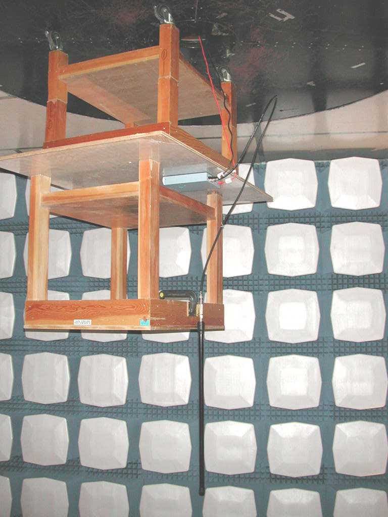
K4BEB03
Aug 02, 2001DSSS data Transceiver for LAN or WAN
Equipment Class
DSS - Part 15 Spread Spectrum Transmitter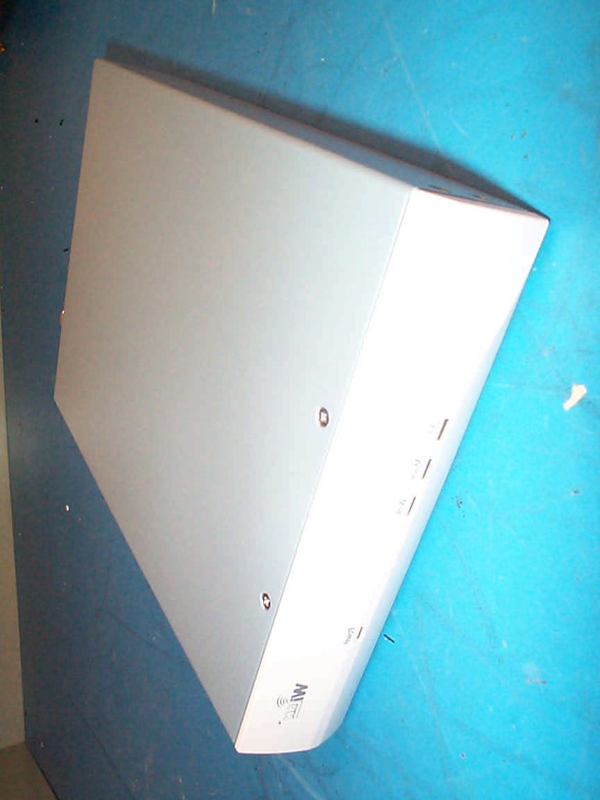
K4BEB02
Apr 17, 2001Advanced Wireless Ethernet Bridge
Equipment Class
DSS - Part 15 Spread Spectrum Transmitter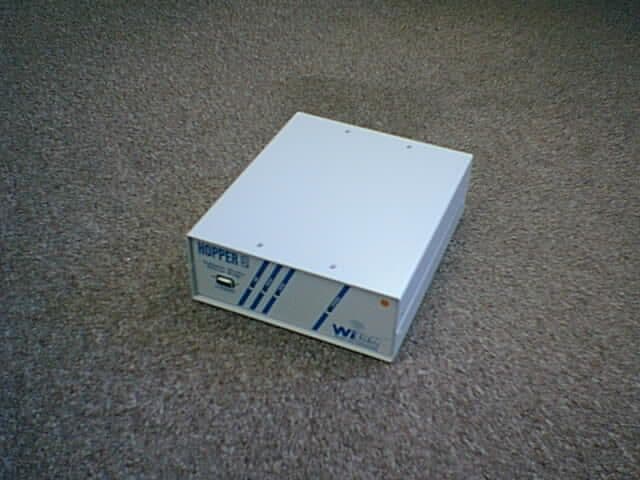
K4BEB01
Aug 25, 2000Wireless Ethernet Bridge
Equipment Class
DSS - Part 15 Spread Spectrum Transmitter