K5IHSC1632HSC 1632
Huge Automations Co Ltd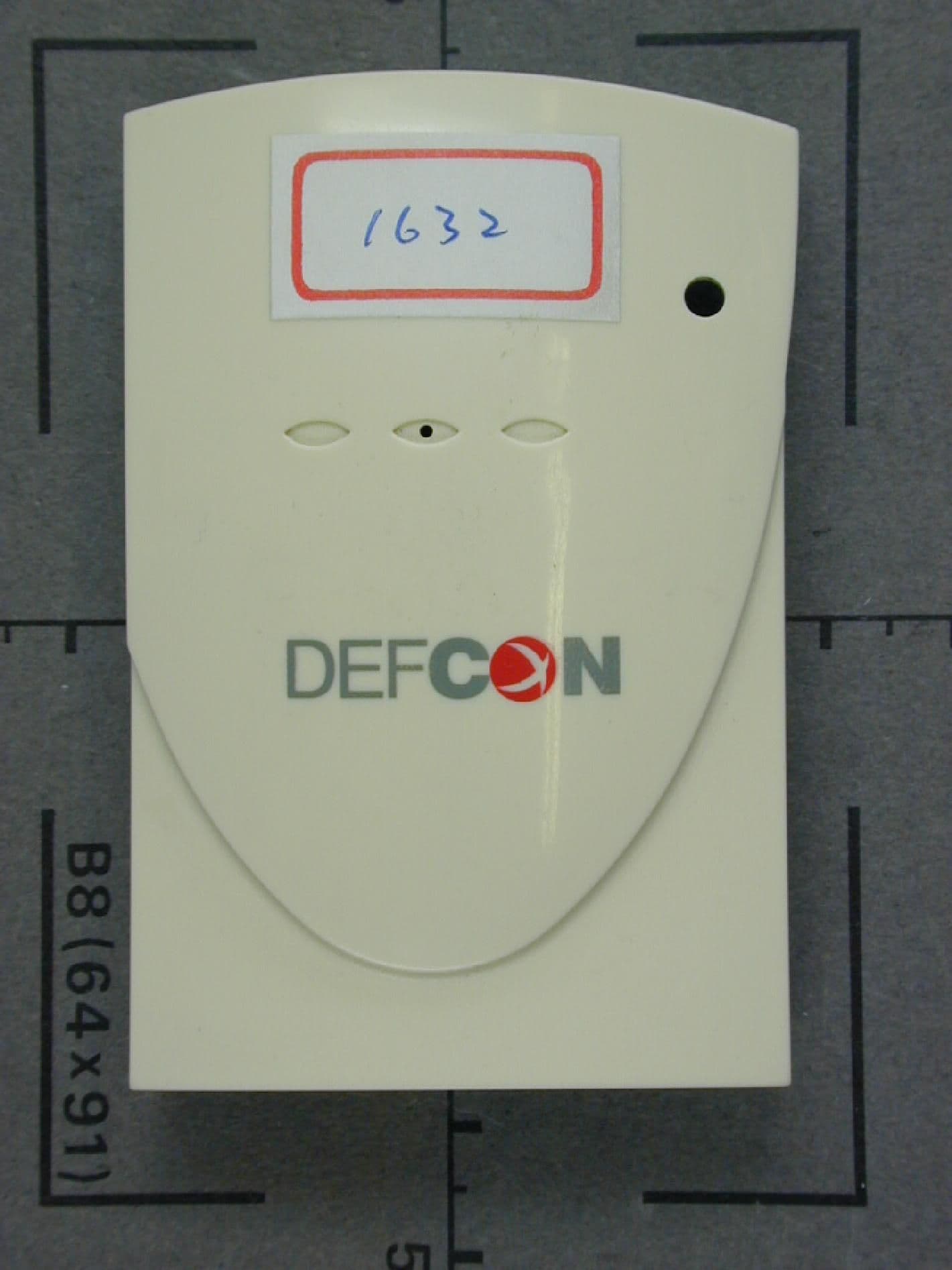
Click to zoom
Application Details
- Equipment Class
- DSC - Part 15 Security/Remote Control Transmitter
- Date of Grant
- Mar 24, 2000
- Application Purpose
- Original Equipment
- Date of Application
- Oct 20, 1999
- Equipment Note
- HSC 1632
- Frequency Range
- 433.05000000 - 434.79000000
- Company
- Huge Automations Co Ltd
- Country
- Taiwan
Documents & Files
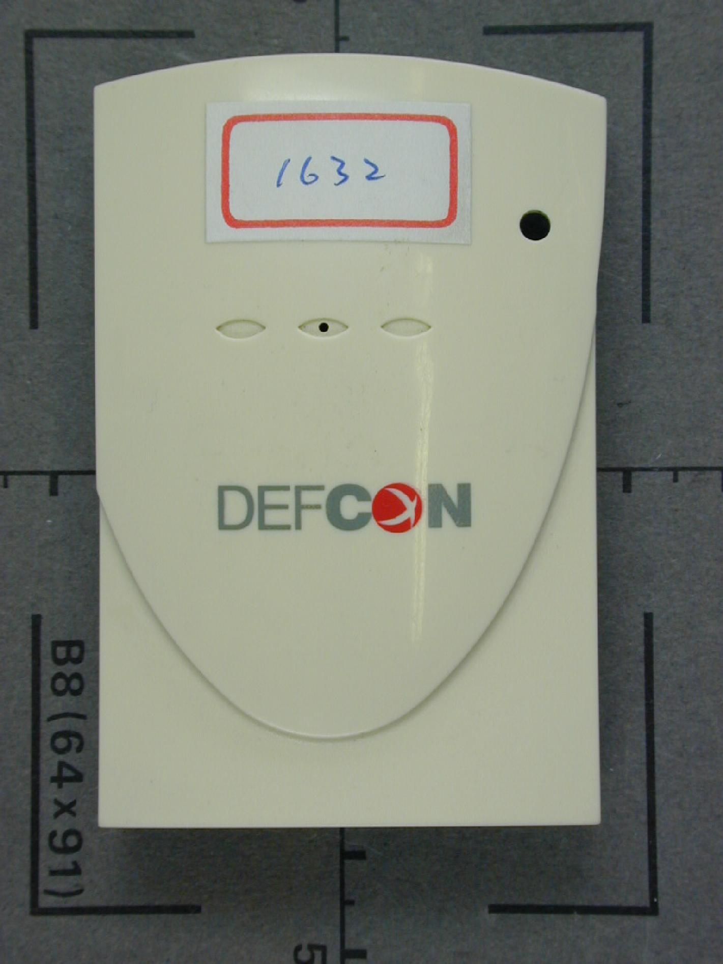
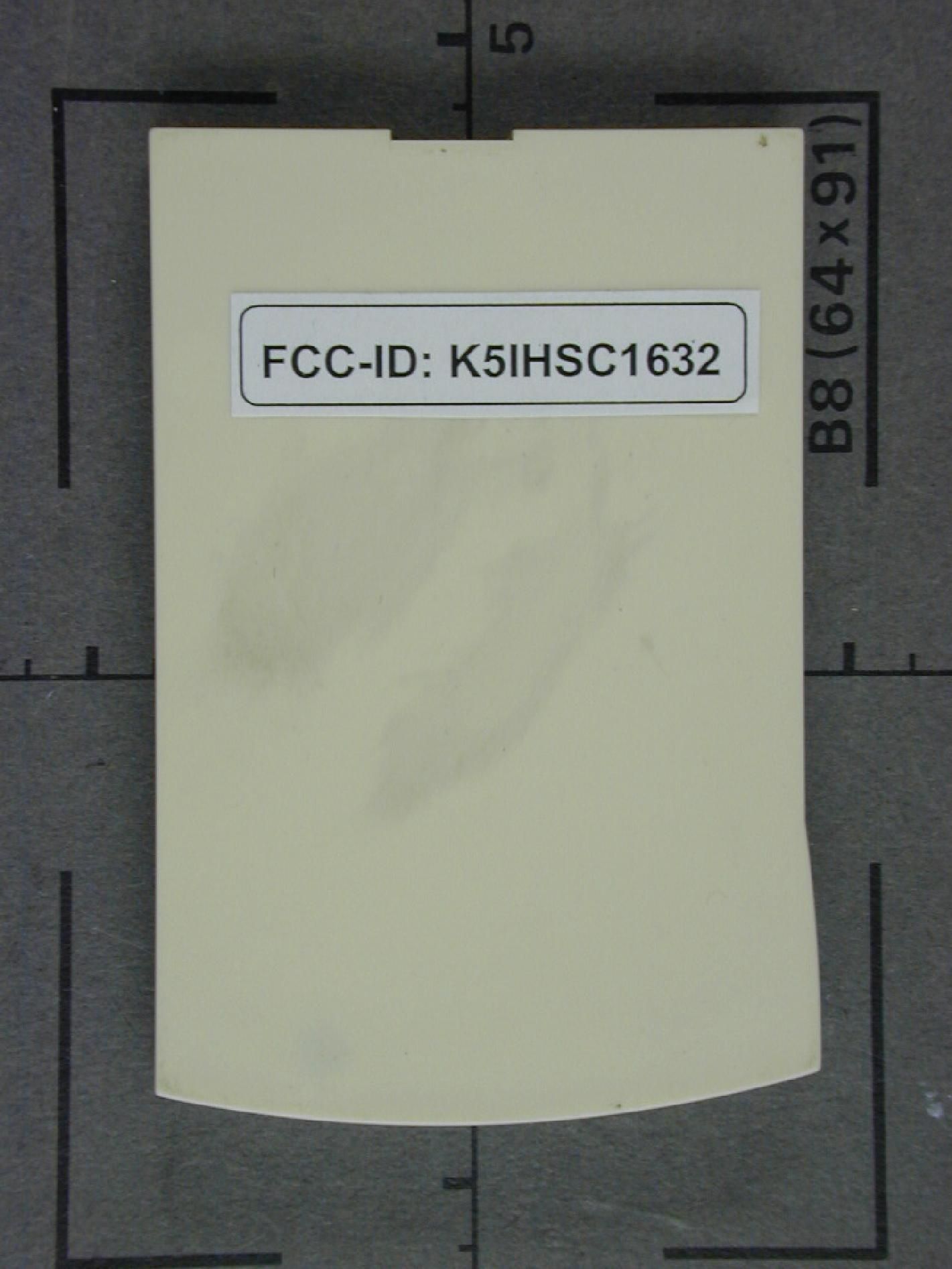
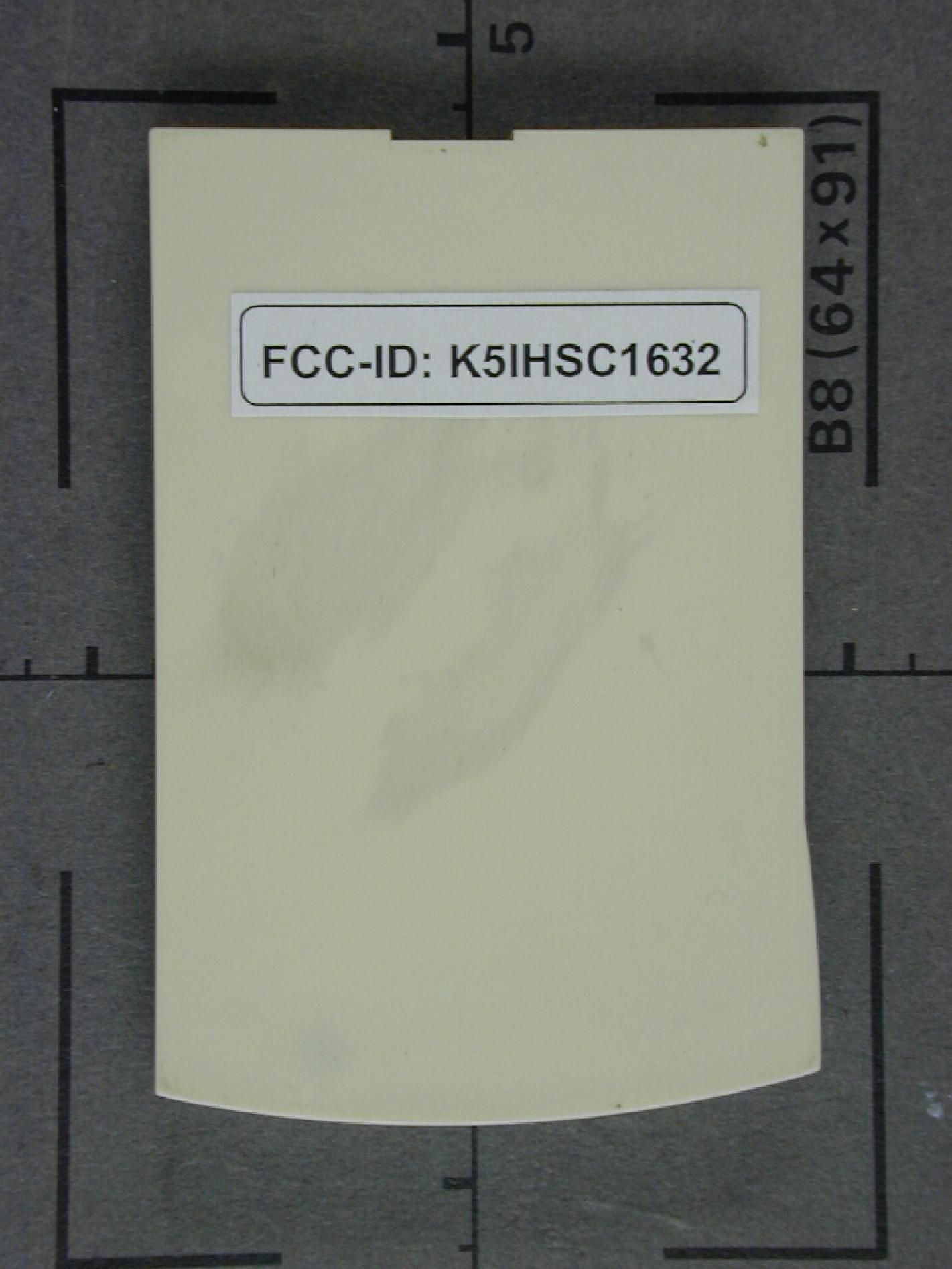
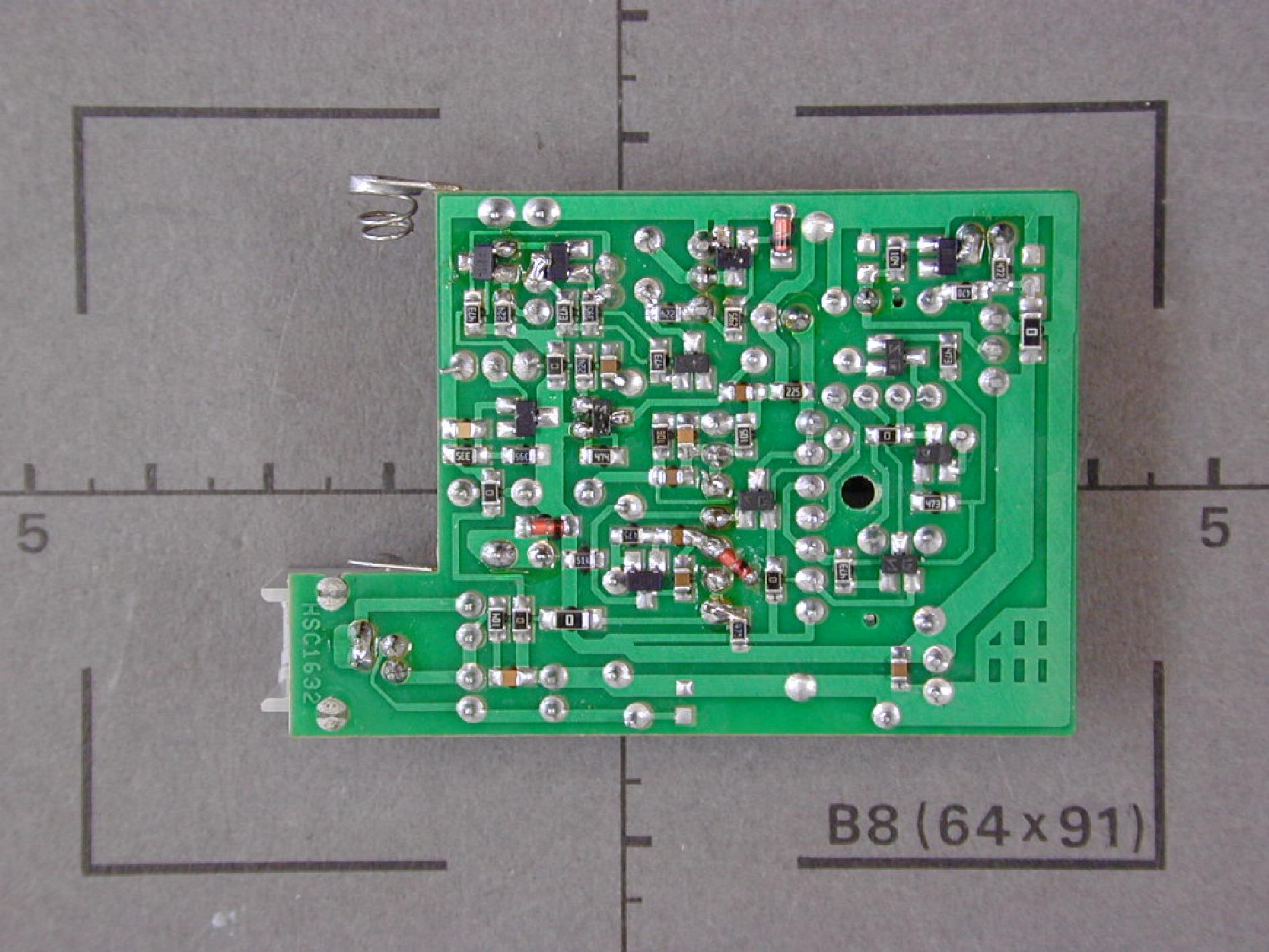
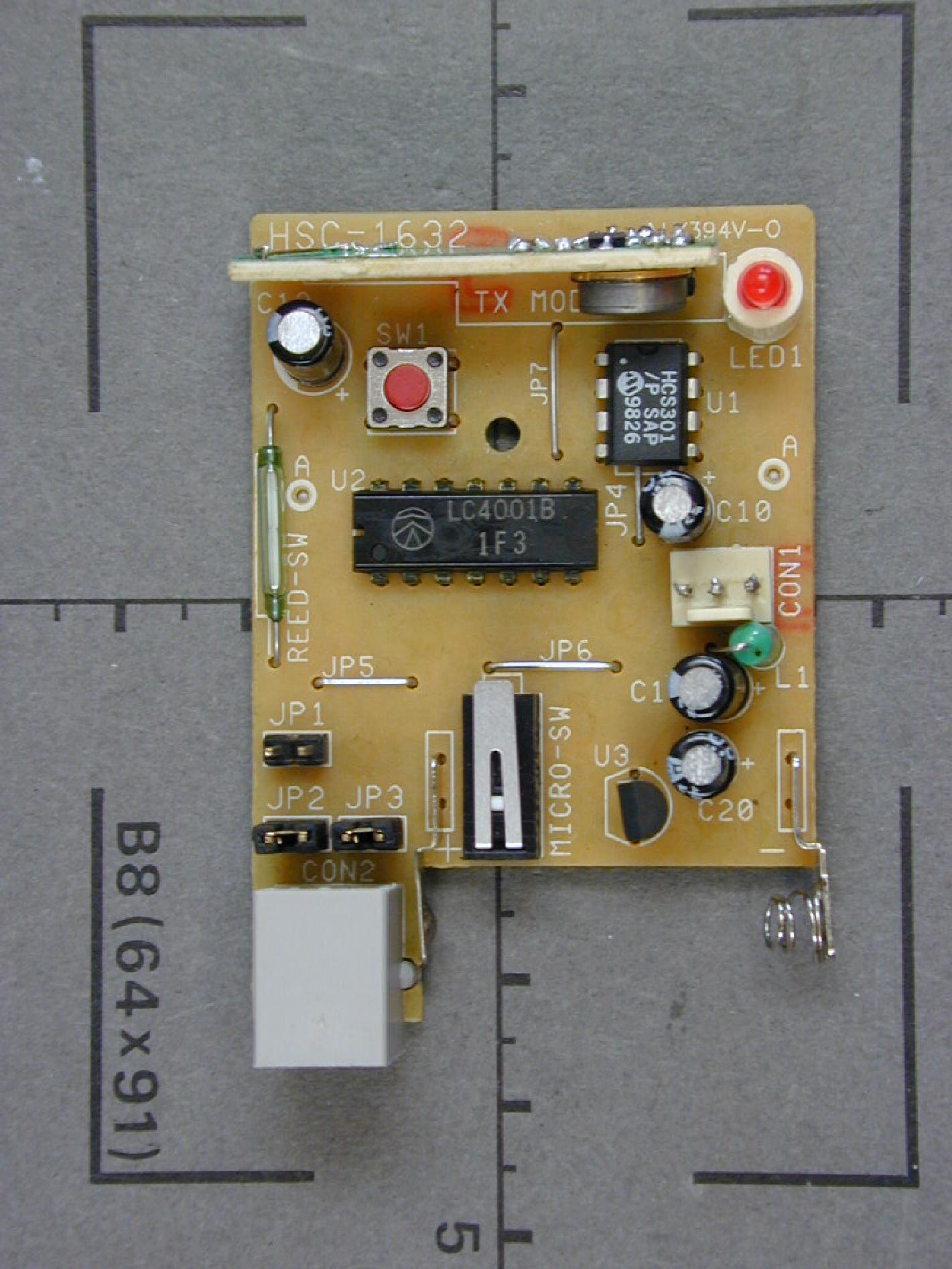
Document Text
Text extracted from the exhibit documents filed with the FCC. Open a document above to read the original.
Users Manual
Application: FCC Compliance statement This device complies with Part 15 of the FCC Rules. Operation is subject to the following two conditions: (1) This device may not cause harmful interference, and (2) this device must accept any interference received, Including interference that may cause undesired operation. Information to the user Changes or modifications not expressly approved by the party responsible for compliance could void the user’s authority to operate the equipment. M a g n e t i c JP1 JP2 JP3 Case2: Increase One Reed Switch JP1 Open JP2 Open JP3 Short Reed Switch HSC-1632 Magnetic JP1 JP2 JP3 M a g n e t i c Case1: Standard JP1 Open JP2 Short JP3 Short HSC-1632 JP1 JP2 JP3 M a g n e t i c Case3: Increase Two Reed Switch JP1 Open JP2 Open JP3 Open HSC-1632 Reed SwitchReed Switch MagneticMagnetic JP1 JP2 JP3 Case4: Use One Reed Switch JP1 Short JP2 Open JP3 Short HSC-1632 Magnetic Reed Switch JP1 JP2 JP3 Case5: Use Two Reed Switch JP1 Short JP2 Open JP3 Open HSC-1632 Reed SwitchReed Switch MagneticMagnetic SPECIFICTION: DC Power: V23A/12V × 1 piece Stand-by Current: 15uA Transmitting Current: 7mA Broadcast Range: 50Meters in open space Operating Temperature: -20 ¢J ~ 40 ¢J Frequency: 433.92MHz Size: 51 × 76 × 30 mm Magnetic LED Buzzer Expanding Socket Reed Switch Tamper Switch Test Button Battery DC12V
Test Report
FCC-ID: K5IHSC1632Test Report No. 56404-90446 Page 1 of 30 Pages EMI/EMC-TestcenterEMV-Prüfzentrum Straubing, March 30, 1999 T E S T - R E P O R T No. 56404-90446 for HSC-1632 Wireless Magnetic Sensor Applicant:Huge Automations Co., Ltd. Purpose of testing:To show compliance with FCC Code of Federal Regulations, Part 15 Subpart C, Section §15.231 Note: The test data of this report relate only to the individual item which has been tested. This report shall not be reproduced except in full extent without the written approval of the testing laboratory. FCC-ID: K5IHSC1632Test Report No. 56404-90446 Page 2 of 30 Pages EMI/EMC-TestcenterEMV-Prüfzentrum Table of Contents 1. Administrative Data3 2. Summary of Test Results4 3. Operation Mode of EUT5 4. Changes made to the EUT during this certification test6 5. Configuration of EUT and Peripheral Devices7 6. Measuring Methods8 7. Photographs Taken During Testing14 8. List of Measurements16 9. Test Results17 10. Equipment List21 11. Charts Taken During Testing23 FCC-ID: K5IHSC1632Test Report No. 56404-90446 Page 3 of 30 Pages EMI/EMC-TestcenterEMV-Prüfzentrum 1.Administrative Data Equipment Under Test (EUT):HSC-1632 Type of equipment:Wireless Magnetic Sensor Parts/accessories:--- Serial number: Version of EUT: FCC-ID:K5IHSC1632 Applicant:Huge Automations Co., Ltd. (full address)No. 35, Lane 36, Ding-Gin Rd., Sanmin Dist., Kaohsiung City, Taiwan, R.O.C. Contract identification:N/A Contact person:Mr. Paul Chen Manufacturer:N/A Receipt of EUT:July 08, 1999 Date of test:August 1999 Responsible for testing:Mr. Johann Roidt Responsible for test report:Mr. Johann Roidt FCC-ID: K5IHSC1632Test Report No. 56404-90446 Page 4 of 30 Pages EMI/EMC-TestcenterEMV-Prüfzentrum 2.Summary of Test Results The tested sample fully complies with the requirements for intentional radiators set forth in the Code of Federal Regulations CFR 47 Part 15 Subpart C, Section §15.231 of the Federal Communication Commission (FCC). Johann Roidt Technical Manager FCC-ID: K5IHSC1632Test Report No. 56404-90446 Page 5 of 30 Pages EMI/EMC-TestcenterEMV-Prüfzentrum 3.Operation Mode of EUT Transmitter in non-conductive test fixture which allows continous operation of the transmitter. FCC-ID: K5IHSC1632Test Report No. 56404-90446 Page 6 of 30 Pages EMI/EMC-TestcenterEMV-Prüfzentrum 4.Changes made to the EUT during this certification test No changes have been made to the EUT during this certification test. FCC-ID: K5IHSC1632Test Report No. 56404-90446 Page 7 of 30 Pages EMI/EMC-TestcenterEMV-Prüfzentrum 5.Configuration of EUT and Peripheral Devices Configuration of cables of EUT Not applicable Configuration of peripheral devices connected to EUT Not applicable FCC-ID: K5IHSC1632Test Report No. 56404-90446 Page 8 of 30 Pages EMI/EMC-TestcenterEMV-Prüfzentrum 6.Measuring Methods 6.1.Transmitter Parameter Tests (§ 15.249 (a)). All transmitter parameter tests were performed at a test-distance of 3 meters in a semi-anechoic room (radiated). During the tests the EUT was rotated all around and the receiving-antenna was raised and lowered from 1 meter to 4 meters to find the maximum levels of emissions. Cables and equipment were placed and moved within the range of position likely to find their maximum emissions. Measurements were made in horizontal and vertical polarization. EUT was operating in transmit mode at the appropriate frequency with its internal modulation. The bandwidth of the emission was measured with a spectrum analyzer. Resolution (RBW) and video bandwidth (VBW) were set to 10 kHz (RBW and VBW) Wooden turntable 70 cm high Test fixture with EUT Semi-anechoic chamber Test distance 3 meter Measuring antenna Spectrum analyzer Test equipment used (see equipment list for details: 02, 08, 10, 40, 61, 64 FCC-ID: K5IHSC1632Test Report No. 56404-90446 Page 9 of 30 Pages EMI/EMC-TestcenterEMV-Prüfzentrum 6.2.Radiated Emissions 30 MHz - 1 GHz (§15.209, §15.231) Radiated emissions were measured over the frequency range from 30 MHz to 1 GHz. The bandwidth of the EMI-receiver was set to 100 kHz and the detector- function was set to CISPR quasi-peak. The test setup was made in accordance with ANSI C63.4-1992. Measurements were made in horizontal and vertical polarization. Preliminary scans were taken in a semi-anechoic room using a spectrum analyzer with the detector function set to peak. All tests were performed at a test-distance of 3 meters. For final testing an open-area test-site was used. During the tests the EUT was rotated all around and the receiving-antenna was raised and lowered from 1 meter to 4 meters to find the maximum levels of emissions. Cables and equipment were placed and moved within the range of position likely to find their maximum emissions. test-distance 3 meters Receiving antenna Spectrum analyzer Wooden Turntable 80 cm high Test fixture with EUT Test equipment used (see equipment list for details: 01, 05, 12, 38, 39, 40, 41, 58, 61, 64, 66 FCC-ID: K5IHSC1632Test Report No. 56404-90446 Page 10 of 30 Pages EMI/EMC-TestcenterEMV-Prüfzentrum 6.3.Radiated Emissions above 1 GHz Radiated emissions were measured in the frequency range 1 GHz to 3.15 GHz in transmit mode .The resolution bandwidth and the video bandwidth of the spectrum analyzer was set to 1 MHz. Prescans with video bandwidth 1 MHz (peak mode) were taken to check out the highest levels (with reference to the limits), see 6.4 for details to prescan procedure. Final measurements were performed at the three highest emissions per band. EUT was rotated all around and receiving antenna was raised and lowered to find the maximum levels of emission. Cables and equipment were placed and moved within the range of position likely to find their maximum emissions. Measurements were made in horizontal and vertical polarization. All tests were performed in a semi-anechoic chamber with a test-distance of 3 meters. To avoid overload in transmit mode a high pass filter was connected to the input of the preamplifier (in case when a preamp…
Text truncated - open the document above for the full version.
Contact Information
Applicant
Chung Chang-Hwa(President)
886 7 342-6911Fax: 886 7 342-8031
Technical Contact
Senton GmbHJohann Roidt
[email protected]+49 9421 55 22 13
Aeussere Fruehlingstrasse 45 · Straubing · Germany
Non-Technical Contact
Senton GmbHJohann Roidt
[email protected]+49 9421 55 22 13
Test Firm
TUV SUD Product Service GmbH PS-EMC-STRRainer Heller
Technical Specifications
| # | Rule Parts | Frequency Range | Power Output | Tolerance |
|---|---|---|---|---|
| 1 | 15C | 433.05 MHz - 434.79 MHz | - | % |
Other Applications from Huge Automations Co Ltd

K5IHSC1672
Jan 31, 2000HSC 1672
Equipment Class
DSC - Part 15 Security/Remote Control Transmitter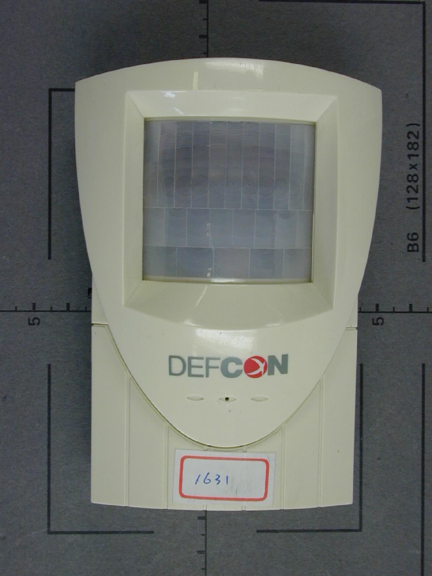
K5IHSC1631
Jan 31, 2000HSC 1631
Equipment Class
DSC - Part 15 Security/Remote Control Transmitter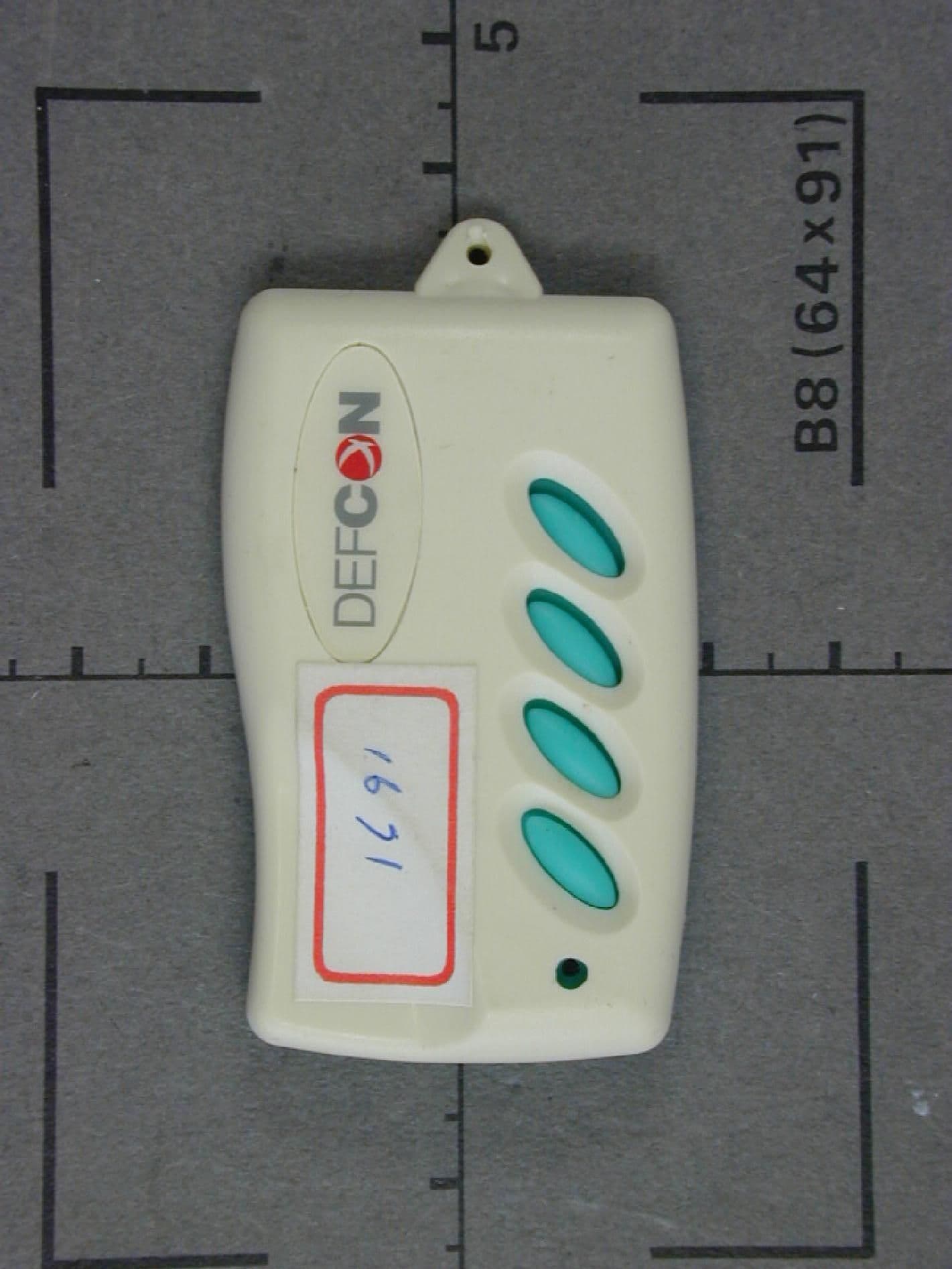
K5IHSC1671
Jan 05, 2000DSC - Part 15 Security/Remote Control Transmitter
Equipment Class
DSC - Part 15 Security/Remote Control TransmitterK5ILD-200SR
May 18, 1995CRR - Superregenerative Receiver
Equipment Class
CRR - Superregenerative ReceiverK5ILD-200ST1
Mar 23, 1995DSC - Part 15 Security/Remote Control Transmitter
Equipment Class
DSC - Part 15 Security/Remote Control Transmitter