K6KA781-MK2A350 Satellite Data Unit
EMS Technologies Canada, Ltd.
Click to zoom
Application Details
- Equipment Class
- TNB - Licensed Non-Broadcast Station Transmitter
- Date of Grant
- May 01, 2013
- Application Purpose
- Original Equipment
- Date of Application
- May 01, 2013
- Equipment Note
- A350 Satellite Data Unit
- Frequency Range
- 1626.50000000 - 1660.50000000
- Country
- Canada
Documents & Files
Document Text
Text extracted from the exhibit documents filed with the FCC. Open a document above to read the original.
Users Manual
Honeywell International Inc. 400 Maple Grove Drive Ottawa, Ontario K2V 1B8 Canada CAGE: 38473 Telephone: (800) 601-309 9 (Toll Free U.S.A./Canada) Telephone: (602) 365-3099 (International Direct) Website:w ww.myaerospace.com Abbreviated Component Maintenance Manual A350 SDU and SCM Part NumberCAGE 1458-A-1101 38473 1458-A-1300 38473 This document contains technical data and is subject to U.S. export regulations. These commodities, technology, or software were exported from the United States in accordance with the export administration regulations. Diversion contrary to U.S. law is prohibited. ECCN: 7E994, NLR Eligible. 23-15-30 Page1of70 Publication Number D201207000045, Revision 0Initial 5 Oct 2012 © Honeywell International Inc. Do not copy without express permission of Honeywell. Interim DRAFT for FCC Approval Purposes Do Not Use for Maintenance 10-Feb-2013 ABBREVIATED COMPONENT MAINTENANCE MANUAL 1458-A-1101 / 1458-A-1300 Honeywell - Confidential THIS COPYRIGHTED WORK AND ALL INFORMATION ARE THE PROPERTY OF HONEYWELL INTERNATIONAL INC., CONTAIN TRADE SECRETS AND MAY NOT, IN WHOLE OR IN PART, BE USED, DUPLICATED, OR DISCLOSED FOR ANY PURPOSE WITHOUT PRIOR WRITTEN PERMISSION OF HONEYWELL INTERNATIONAL INC. ALL RIGHTS RESERVED. Honeywell Materials License Agreement The documents and information contained herein ("the Materials") are the proprietary data of Honeywell International Inc. and Honeywell Intellectual Properties Inc. (collectively "Honeywell"). These Materials are provided for the exclusive use of Honeywell Service Centers; Honeywell-authorized repair facilities; operators of Honeywell aerospace products subject to an applicable product support agreement, their wholly owned-subsidiaries or a formally designated third party service provider; and direct recipients of Materials from Honeywell’s Aerospace Technical Publication Distribution. The terms and conditions of this License Agreement govern your use of these Materials, except to the extent that any terms and conditions of another applicable agreement with Honeywell regarding the operation, maintenance, or repair of Honeywell aerospace products conflict with the terms and conditions of this License Agreement, in which case the terms and conditions of the other agreement will govern. However, this License Agreement will govern in the event of a conflict between its terms and conditions and those of a purchase order or acknowledgement. 1. License Grant - If you are a party to an applicable product support agreement, a Honeywell Service Center agreement, or an authorized repair facility agreement, Honeywell hereby grants you a limited, non-exclusive license to use these Materials to operate, maintain, or repair Honeywell aerospace products only in accordance with that agreement. If you are a direct recipient of these Materials from Honeywell’s Aerospace Technical Publication Distribution and are not a party to an agreement related to the operation, maintenance or repair of Honeywell aerospace products, Honeywell hereby grants you a limited, non-exclusive license to use these Materials to maintain or repair the subject Honeywell aerospace products only at the facility to which these Materials have been shipped ("the Licensed Facility"). Transfer of the Materials to another facility owned by you is permitted only if the original Licensed Facility retains no copies of the Materials and you provide prior written notice to Honeywell. 2. Rights In Materials - Honeywell retains all rights in these Materials and in any copies thereof that are not expressly granted to you, including all rights in patents, copyrights, trademarks, and trade secrets. No license to use any Honeywell trademarks or patents is granted under this License Agreement. 3. Confidentiality - You acknowledge that these Materials contain information that is confidential and proprietary to Honeywell. You agree to take all reasonable efforts to maintain the confidentiality of these Materials. 4. Assignment And Transfer - This License Agreement may be assigned to a formally designated service designee or transferred to a subsequent owner or operator of an aircraft containing the subject Honeywell aerospace products. However, the recipient of any such assignment or transfer must assume all of your obligations under this License Agreement. No assignment or transfer shall relieve any party of any obligation that such party then has hereunder. 5. Copies of Materials - Unless you have the express written permission of Honeywell, you may not make or permit making of copies of the Materials. Notwithstanding the foregoing, you may make copies of only portions of the Material for your internal use. You agree to return the Materials and any copies thereof to Honeywell upon the request of Honeywell. 6. Term - This License Agreement is effective until terminated as set forth herein. This License Agreement will terminate immediately, without notice from Honeywell, if you fail to comply with any provision of this 23-15-30 Page2of70 5 Oct 2012 © Honeywell International Inc. Do not copy without express permission of Honeywell. Interim DRAFT for FCC Approval Purposes Do Not Use for Maintenance 10-Feb-2013 ABBREVIATED COMPONENT MAINTENANCE MANUAL 1458-A-1101 / 1458-A-1300 License Agreement or will terminate simultaneously with the termination or expiration of your applicable product support agreement, authorized repair facility agreement, or your formal designation as a third party service provider. Upon termination of this License Agreement, you will return these Materials to Honeywell without retaining any copies and will have one of your authorized officers certify that all Materials have been returned with no copies retained. 7. Remedies - Honeywell reserves the right to pursue all available remedies and damages resulting from a breach of this License Agreement. 8. Limitation of Liability - Honeywell does not make any representation regarding the use or sufficiency of the Materials. THE…
Text truncated - open the document above for the full version.
External Photos
A350 Isometric External View A350 Front External View A350 Rear External View
ID Label/Location Info
1458D1416REVA00.CDR JOE AZEVEDO A350 FCC ID LABEL, A350, SDU 1458-D-1416 A00 NTS NOTE: 1. USE BLANK LABEL STOCK (ITEM 10) WITH ARTWORK (ITEM 30) TO PERMANENTLY MARK IDENTIFICATION LABEL FOR: - FCC ID - FCC STATEMENT 2. THE BORDER OF THE LABEL ARE SHOWN FOR ORIENTATION PURPOSES ONLY. 3. PROTECT COMPLETED LABEL BY APPLYING OVERLAMINATE (ITEM 20). 4. IF REQUIRED, CUT THE LABEL TO THE WIDTH SHOWN. 11OCT12 SEE SEPARATE PARTS LIST 400 MAPLE GROVE ROAD OTTAWA, ONTARIO K2V 1B8 J. AZEVEDO P. MARCHAND I. MILANOVIC CorelDraw 12 K. CULLEN P. BUNYON A00 ALPHA RELEASE 11OCT12 JA N/A N/A 0 . 7 5 ” 2.25” FCC ID: K6KA781-MK2 This device complies with part 15 of the FCC Rules. Operation is subject to the following two conditions: (1) This device may not cause harmful interference, and (2) This device must accept any interference received, including interference that may cause undesired operation. 16-FEB-11 15-FEB-11 15-FEB-11 16-FEB-11 16-FEB-11 16-FEB-11 15-FEB-11 S. MULDER N. IBRAHIM
Internal Photos
This document contains information that is proprietary and confidential to either or both of EMS Technologies Canada, Ltd., or EMS Aviation Inc. (collectively “EMS Aviation”). Neither this document nor the information contained within may be disclosed or copied without the prior written permission of EMS Aviation. © 2012 EMS Technologies Canada, Ltd., EMS Aviation Inc. Page 1 Table of Figures Figure 1 1485-A-1142 Splitter Combiner ...................................................................................... 2 Figure 2 1458-F-1143 Power Supply ............................................................................................. 2 Figure 3 1394-F-1117 10 MHz Reference OCXO ......................................................................... 3 Figure 4 1210-A-1510 MCC Channel Card Top ........................................................................... 3 Figure 5 1210-A-1510 MCC Channel Card Bottom ...................................................................... 4 Figure 6 1210-A-1510 MCC Channel Card Part Numbers ............................................................ 4 Figure 7 1458-A-1103 Control and Data Processor Top ............................................................... 5 Figure 8 1458-A-1103 Control and Data Processor Bottom .......................................................... 5 Figure 9 1458-A-1103 Control and Data Processor Part numbers ................................................ 6 Figure 10 1210-A-0002-01 HSD Digital Module Base Card Top with 1210-A0010 RF Module 6 Figure 11 1210-A-0002-01 HSD Digital Module (Part of BGAN Channel) Bottom ................... 7 Figure 12 1210-A-0002-01 HSD Digital Module (Part of BGAN Channel card) Part Numbers . 7 PROPRIETARY NOTICE This document contains information that is proprietary and confidential to either or both of EMS Technologies Canada, Ltd., or EMS Aviation Inc. (collectively “EMS Aviation”) and is supplied on the express condition that it is not to be used for any purpose other than the purpose for which it was issued, nor is it to be copied or communicated in whole or in part, to any third party other than the recipient organization, without the prior written permission of EMS Aviation. © 2012 EMS Technologies Canada, Ltd., EMS Aviation Inc. This document contains information that is proprietary and confidential to either or both of EMS Technologies Canada, Ltd., or EMS Aviation Inc. (collectively “EMS Aviation”). Neither this document nor the information contained within may be disclosed or copied without the prior written permission of EMS Aviation. © 2012 EMS Technologies Canada, Ltd., EMS Aviation Inc. Page 2 Figure 1 1485-A-1142 Splitter Combiner Figure 2 1458-F-1143 Power Supply This document contains information that is proprietary and confidential to either or both of EMS Technologies Canada, Ltd., or EMS Aviation Inc. (collectively “EMS Aviation”). Neither this document nor the information contained within may be disclosed or copied without the prior written permission of EMS Aviation. © 2012 EMS Technologies Canada, Ltd., EMS Aviation Inc. Page 3 Figure 3 1394-F-1117 10 MHz Reference OCXO Figure 4 1210-A-1510 MCC Channel Card Top This document contains information that is proprietary and confidential to either or both of EMS Technologies Canada, Ltd., or EMS Aviation Inc. (collectively “EMS Aviation”). Neither this document nor the information contained within may be disclosed or copied without the prior written permission of EMS Aviation. © 2012 EMS Technologies Canada, Ltd., EMS Aviation Inc. Page 4 Figure 5 1210-A-1510 MCC Channel Card Bottom Figure 6 1210-A-1510 MCC Channel Card Part Numbers This document contains information that is proprietary and confidential to either or both of EMS Technologies Canada, Ltd., or EMS Aviation Inc. (collectively “EMS Aviation”). Neither this document nor the information contained within may be disclosed or copied without the prior written permission of EMS Aviation. © 2012 EMS Technologies Canada, Ltd., EMS Aviation Inc. Page 5 Figure 7 1458-A-1103 Control and Data Processor Top Figure 8 1458-A-1103 Control and Data Processor Bottom This document contains information that is proprietary and confidential to either or both of EMS Technologies Canada, Ltd., or EMS Aviation Inc. (collectively “EMS Aviation”). Neither this document nor the information contained within may be disclosed or copied without the prior written permission of EMS Aviation. © 2012 EMS Technologies Canada, Ltd., EMS Aviation Inc. Page 6 Figure 9 1458-A-1103 Control and Data Processor Part numbers Figure 10 1210-A-0002-01 HSD Digital Module Base Card Top with 1210-A0010 RF Module (BGAN Channel Card) This document contains information that is proprietary and confidential to either or both of EMS Technologies Canada, Ltd., or EMS Aviation Inc. (collectively “EMS Aviation”). Neither this document nor the information contained within may be disclosed or copied without the prior written permission of EMS Aviation. © 2012 EMS Technologies Canada, Ltd., EMS Aviation Inc. Page 7 Figure 11 1210-A-0002-01 HSD Digital Module (Part of BGAN Channel) Bottom Figure 12 1210-A-0002-01 HSD Digital Module (Part of BGAN Channel card) Part Numbers
Test Report
p12a0002_FCC_Part 87_Rev 2.0 Page: 1 of 49 Test Report Prepared for: EMS Technologies of Canada, Ltd., now part of Honeywell Model: A350 Part number 1458-A-1100 Description: A350 Satellite Data Unit To FCC Part 87 Date of Issue: October 18, 2012 On the behalf of the applicant: EMS Technologies of Canada, Ltd., now part of Honeywell 400 Maple Grove Rd. Ottawa, ON K2V 1B8 Canada Attention of: Ron Halka, Manager Sr. Product Mfg. Eng. Phone: (613) 591-9040 E-Mail: [email protected] Prepared by Compliance Testing, LLC 3356 N San Marcos Pl, Suite 107 Chandler, AZ 85225-7176 (866) 311-3268 phone / (480) 926-3598 fax www.compliancetesting.com Project No: p12a0002 John Erhard Project Test Engineer This report may not be reproduced, except in full, without written permission from Compliance Testing All results of this test report relate only to the item(s) there were tested p12a0002_FCC_Part 87_Rev 2.0 Page: 2 of 49 Test Report Revision History Revision Date Revised By Reason for Revision 1.0 October 18, 2012 John Erhard Original Document 2.0 April 3, 2013 Karen Springer Corrected Emission Designator p12a0002_FCC_Part 87_Rev 2.0 Page: 3 of 49 Table of Contents Description Page Standard Test Conditions Engineering Practices ......................................................................................... 5 Carrier Output Power (Conducted) ............................................................................................................. 7 Conducted Spurious Emissions ................................................................................................................. 8 Field Strength of Spurious Radiation ........................................................................................................ 17 Emission Masks (Occupied Bandwidth) .................................................................................................... 21 Frequency Stability (Temperature Variation) ............................................................................................. 44 Frequency Stability (Voltage Variation) ..................................................................................................... 45 Necessary Bandwidth and Emission Bandwidth ......................................................................................... 46 Test Equipment Utilized: ......................................................................................................................... 49 p12a0002_FCC_Part 87_Rev 2.0 Page: 4 of 49 ILAC / A2LA Compliance Testing, LLC, has been accredited in accordance with the recognized International Standard ISO/IEC 17025:2005. This accreditation demonstrates technical competence for a defined scope and the operation of a laboratory quality management system (refer joint ISO-ILAC-IAF Communiqué dated January 2009) The tests results contained within this test report all fall within our scope of accreditation, unless noted in the table below Please refer to http://www.compliancetesting.com/labscope.html for current scope of accreditation. Testing Certificate Number: 2152.01 FCC OATS Reg, #933597 IC Reg. #2044A-1 Non-accredited tests contained in this report: N/A p12a0002_FCC_Part 87_Rev 2.0 Page: 5 of 49 Standard Test Conditions Engineering Practices All tests and measurement data shown were performed in accordance with FCC Rules and Regulations, Volume II; Part 2, Sub-part J, Sections 2.947, 2.1033(c), 2.1041, 2.1046, 2.1047, 2.1051, 2.1053, 2.1055, 2.1057 and the following individual Parts: 87. Except as noted herein, the following conditions and procedures were observed during the testing. In accordance with ANSI C63.10-2009 and unless otherwise indicated in the specific measurement results, the ambient temperature of the actual EUT was maintained within the range of 10° to 40°C (50° to 104°F) unless the particular equipment requirements specify testing over a different temperature range. Also, unless otherwise indicated, the humidity levels were in the range of 10% to 90% relative humidity. Measurement results, unless otherwise noted, are worst-case measurements. Environmental Conditions Temperature (º C) Humidity (%) Pressure (mbar) 26.20 36.10 966.900 EUT Description Model: A350 Part number 1458-A-1100 Description: A350 Satellite Data Unit Firmware: N/A Software: N/A Additional Information The EUT is an aviation earth station. EUT Operation during Tests The EUT was in a normal hardware configuration with a rack mount PC running test software allowing manual control of the radio functions. . p12a0002_FCC_Part 87_Rev 2.0 Page: 6 of 49 Test Results Summary Specification Test Name Pass, Fail, N/A Comments 2.1046, 87.131 Carrier Output Power (Conducted) Pass 2.1051, 87.139(i)(1) Unwanted Emissions (Transmitter Conducted) Pass 2.1053 Field Strength of Spurious Radiation Pass 2.1049, 87.139(i)(3) Emission Masks (Occupied Bandwidth) Pass See FCC waiver for allowable variance 2.1047 Audio Low Pass Filter (Voice Input) N/A The EUT does not contain an audio input 2.1047 Audio Frequency Response N/A The EUT does not contain an audio input 2.1047 Modulation Limiting N/A The EUT does not contain an audio input 2.1055, 87.133(a) Frequency Stability (Temperature Variation) Pass 2.1055, 87.133(a) Frequency Stability (Voltage Variation) Pass p12a0002_FCC_Part 87_Rev 2.0 Page: 7 of 49 Carrier Output Power (Conducted) Name of Test: Carrier Output Power (Conducted) Engineer: John Erhard Test Equipment Utilized: i00331 Test Date: 10/15/2012 Test Procedure The Equipment Under Test (EUT) was connected directly to a spectrum analyzer with the RBW set to 1 MHz and the VBW set to 3 X RBW. This guaranteed that the RBW was greater than the transmit signal occupied bandwidth ensuring there was no signal suppression. The peak readings were taken for each modulation type and the result was then compared to the limit. Test Setup BPSK Transmitter Peak Output Power Tuned Frequency (MHz) Measured Power (dBm) Measured Power (W) Limit (W) Re…
Text truncated - open the document above for the full version.
Test Setup Photos
Page 1 of 3 Test Setup Photos: EMS Technologies FCC ID: K6KA781-MK2 Conducted Frequency Conducted Frequency Page 2 of 3 Radiated Radiated Page 3 of 3 Radiated
Contact Information
Applicant
Subhadeep Pal(Director of Engineering - SATCOM)
Technical Specifications
| # | Rule Parts | Frequency Range | Power Output | Emission | Tolerance |
|---|---|---|---|---|---|
| 15 | 87 | 1.63 GHz - 1.66 GHz | 50.1 W | 840HG1D | 320 Hz |
Other Applications from EMS Technologies Canada, Ltd.
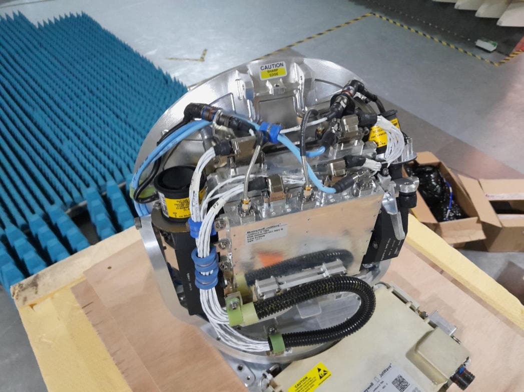
K6KJETWAVE4
Mar 09, 2026Jetwave X
Equipment Class
TNB - Licensed Non-Broadcast Station Transmitter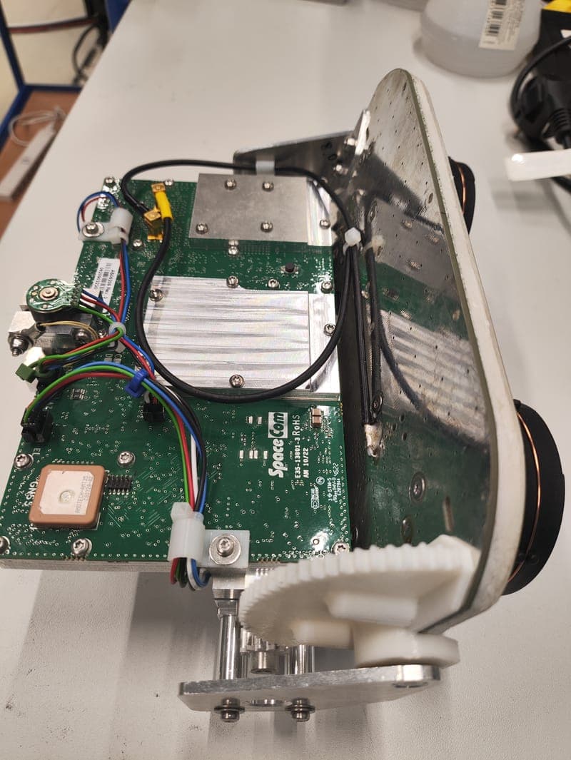
K6KSATCOM5G
Apr 17, 2024L Band SATCOM terminal with 5G cellular modem
Equipment Class
TNB - Licensed Non-Broadcast Station Transmitter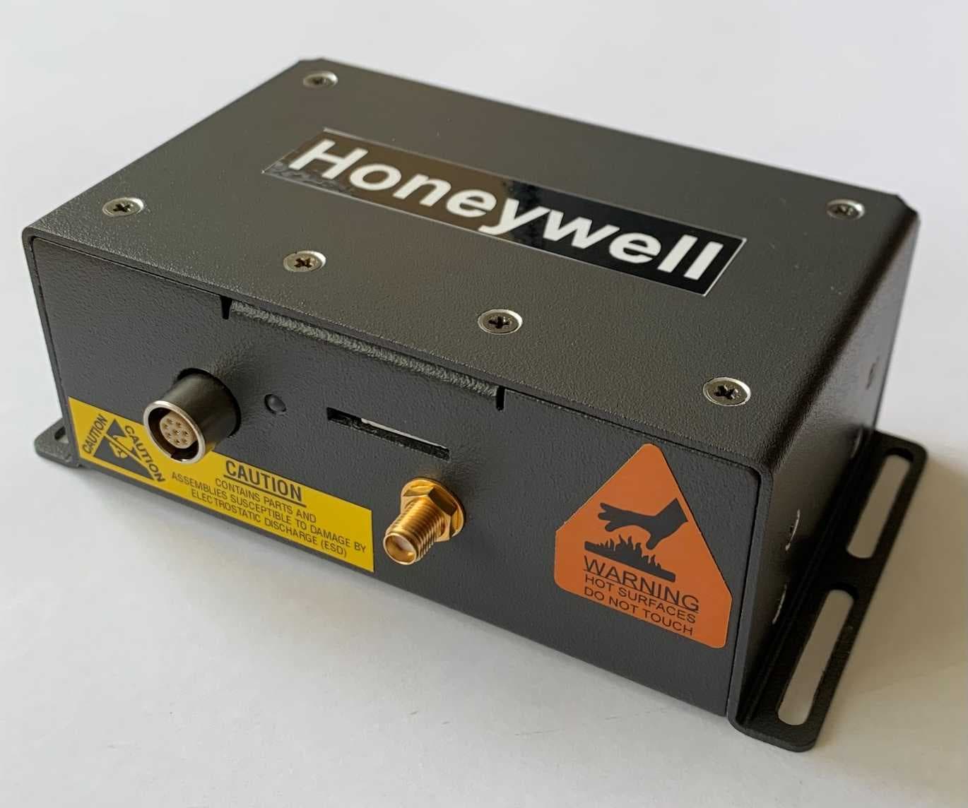
K6KSMALLSATCOM
May 16, 2021Small UAV Satcom
Equipment Class
TNB - Licensed Non-Broadcast Station Transmitter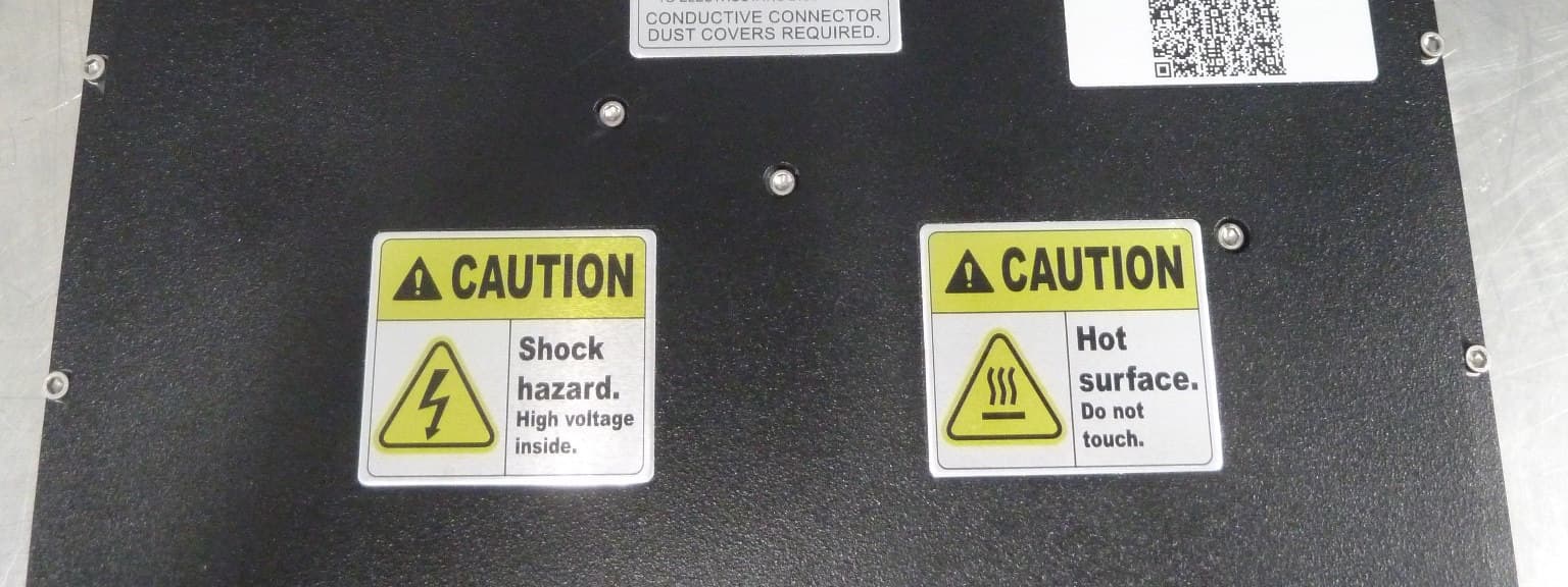
K6KJETWAVE3
Dec 22, 2020Jetwave
Equipment Class
TNB - Licensed Non-Broadcast Station Transmitter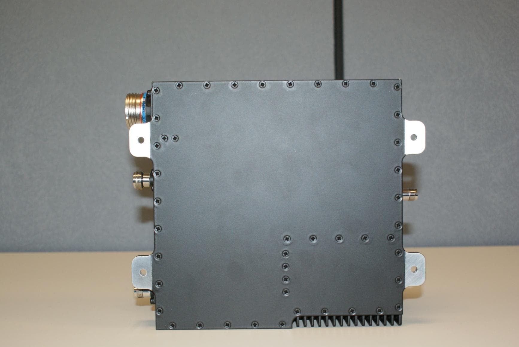
K6KIPLD
Sep 17, 2020Aircraft Earth Station
Equipment Class
TNB - Licensed Non-Broadcast Station Transmitter