K6KA781-MK3A781-200 Satcom Transceiver
EMS Technologies Canada, Ltd.
Click to zoom
Application Details
- Equipment Class
- TNB - Licensed Non-Broadcast Station Transmitter
- Date of Grant
- Jul 02, 2012
- Application Purpose
- Original Equipment
- Date of Application
- Jul 02, 2012
- Equipment Note
- A781-200 Satcom Transceiver
- Frequency Range
- 1626.50000000 - 1660.50000000
- Country
- Canada
Documents & Files
Document Text
Text extracted from the exhibit documents filed with the FCC. Open a document above to read the original.
Users Manual
23-15-30TITLE PAGE T-1 DATE TBD ARINC 781-200 SDU and SCM System Description, Installation, and Maintenance Manual MN-0000243, Revision 1.0 This document provides procedures for the equipment listed below. ModelPart Number ARINC 781-200 Satellite Data Unit1530-A-1100 ARINC 781-200 SDU Configuration Module—Single SBB 1530-A-1300-01 ARINC 781-200 SDU Configuration Module—Dual SBB 1530-A-1300-02 23-15-30TITLE PAGE T-2 DATE TBD PROPRIETARY STATEMENT This document contains information that is proprietary and confid ential to either or both of EMS Technologies Canada, Ltd., or EMS Aviation Inc. (collectively "EMS Aviation") and is supplied on the express condition that it is not to be used for any purpose other than the purpose for which it was issued, nor is it to be copied or communicated in whole or in part, to any third party other than the recipient organization, without the prior written permission of EMS Aviation. © 2012 EMS Technologies Canada, Ltd., EMS Aviation Inc. ARINC 781-200 SDU and SCM System Description , Installation, and Maintenance Manual Document Number: MN-0000243, Revision 1.0 Revision Table RevisionECRDescription Windows® is a registered trademark of Microsoft Corporation in the United States and other countries. Other product, brand, service, and company names herein are the trademarks of their respective owners. Our products are under continuous research and devel opment. Any information may therefore be changed without prior notice. EMS Aviation reserves the right to make improvements or changes in the product described in this manual at any time without notice. While reasonable efforts have been made in the preparation of this document to assure its accuracy, EMS Aviation assumes no liability resulting from any errors or omissions in this document, or from the use of the information contained herein. Printed in Canada. EMS Aviation 400 Maple Grove Road, Ottawa, Ont ario, K2V 1B8, CANADA EMS Aviation Reception:(613) 591-9064 EMS Aviation Product Support:(888) 300-7415 (calls are routed to an on-call Product Support specialist after regular business hours) +44 1684 290 020 (UK) (613) 591-3086 (outside North America) EMS Aviation E-mail Help:[email protected] EMS Aviation Web site:www.emsaviation.com EMS Aviation Sales and Marketing:800-600-9759 23-15-30CR-1 DATE TBD CUSTOMER RESPONSE FORM To help us improve the quality of our product documentation, EMS Aviation would appreciate your comments and suggestions on this publication. Please complete the following customer survey and send to EMS Aviation at: EMS Aviation 400 Maple Grove Road Ottawa, ON K2C 0P9 E-mail: [email protected] Publication information: Publication number:MN-0000243 Publication title:ARINC 781-200 SDU and SCM System Descr iption, Installation, and Maintenance Manual Latest issue date:DATE TBD Document revision:1.0 Customer information: Name: Company: Tel: Fax: Email: Comments and suggestions: Date: Comments: 23-15-30CR-2 DATE TBD Blank Page SYSTEM DESCRIPTION, INSTALLATION, AND MAINTENANCE MANUAL ARINC 781-200 SDU and SCM 23-15-30RR-1 DATE TBD RECORD OF REVISIONS When revisions are received, insert revised pages, record the date, and initial. Revision Number Issue Date Date Inserted Inserted b y (initial) Revision Number Issue Date Date Inserted Inserted by (initial) SYSTEM DESCRIPTION, INSTALLATION, AND MAINTENANCE MANUAL ARINC 781-200 SDU and SCM 23-15-30RR-2 DATE TBD Blank Page SYSTEM DESCRIPTION, INSTALLATION, AND MAINTENANCE MANUAL ARINC 781-200 SDU and SCM 23-15-30SBL-1 DATE TBD SERVICE BULLETIN LIST Service Bulletin Number Subject Manual Rev. Number Manual Rev. Da te SYSTEM DESCRIPTION, INSTALLATION, AND MAINTENANCE MANUAL ARINC 781-200 SDU and SCM 23-15-30SBL-2 DATE TBD Blank Page SYSTEM DESCRIPTION, INSTALLATION, AND MAINTENANCE MANUAL ARINC 781-200 SDU and SCM 23-15-30LEP-1 DATE TBD LIST OF EFFECTIVE PAGES * An asterisk indicates pages changed, added, or deleted by the current revision. F ind icates a right foldout page with a blank back. SectionPageDate SYSTEM DESCRIPTION, INSTALLATION, AND MAINTENANCE MANUAL ARINC 781-200 SDU and SCM 23-15-30LEP-2 DATE TBD Blank Page SYSTEM DESCRIPTION, INSTALLATION, AND MAINTENANCE MANUAL ARINC 781-200 SDU and SCM 23-15-30TC-1 DATE TBD TABLE OF CONTENTS INTRODUCTION 1. Illustration of Equipment ............................................................................. INTRO-1 2. Acronyms and Abbreviations ..................................................................... INTRO-2 3. Safety Advisories ......................................................................................... INTRO-4 SYSTEM DESCRIPTION 1. Inmarsat System Overview................................................................................... 1-1 2. Equipment Overview ............................................................................................. 1-2 A. SDU ................................................................................................................................. 1-3 B. SCM ................................................................................................................................. 1-3 3. Equipment Specifications .................................................................................... 1-4 4. System Interfaces.................................................................................................. 1-6 A. SDU ................................................................................................................................. 1-7 B. SCM ................................................................................................................................. 1-8 5. User Interfaces ...................................................................................................... 1-8 A. MCDU .............................................................................................................................. 1-8 B. 4-Wire Audio ..........................…
Text truncated - open the document above for the full version.
Cover Letter(s)
Fn'S_. [:\l\ le'cllnt,lLryr.:( ¡n¡'ia [.td -f ¡1. ll tjl] i9l1)()6-[ [-\l! \t irrtiu¡i - (,)tt¿ir,.u I ¡11. f l ôli iql (/l](.) -l{lt) \llrIl¡ ('irrrr.. [ìr)irtl \\\\\\ itììsir\iiriìrì!1.(\)¡rl ( )ltiì\\:r- ()N l<l\ I llfÌ C.lìttlrl:: Avrnnorv 4 May 2010 Federal Aviation Administration Office of Spectrum Policy and Management ASR-1 800 lndependence Avenue, SW Washington D.C.20591 Reference: FAA Notification of FCC Equipment under FCC Part 87 4781,4781-MK2, and A78l-MK3, Aeronautical Earth Station Satellite Gommunications Transceive¡s FCG l.D.'s K6K4781, KOKA781-MK2, and K6KA781-MK3 Dear Sir, ln accordance with Federal Communications Commission (FCC) Rules and Regulations, Part 87.147(d), EMS Technologies Canada, Ltd. (EMS) hereby notifies the Federal Aviation Administration of its filing with the FCC of an application for certification of the 4781 Aeronautical Earth Station Satellite Communications Transceiver models referenced above. Please find below the information required pursuant to Part 87.147(d)(1). f ) Description of Equipment The EMS 4781 Aeronautical Earth Station (AES) satellite communication transceiver supports the lnmarsat Classic-Aero H+, Swift64, and SwiftBroadband aeronautical satellite communications services. The A781 meets the applicable requirements of ARINC Characteristic 781 "Mark 3 Aviation Satellite Communication Systems" and RTCA/DO-210D "Minimum Operational Performance Standards for Geosynchronous Orbit Aeronautical Mobile Satellite Services (AMSS) Avionics". The 4781 transceiver system consists of an 4781 Satellite Data Unit (SDU), an SDU Configuration Module (SCM), and an optional Flange Mount Power Amplifier (FMPA). The SDU is packaged in a six Modular Concept Unit (6-MCU) enclosure as defined in ARINC Specification 600. The SDU contains 2 channel card circuit card assemblies (CCA), an RF power amplifier, a voice and data processor CCA, a control processor CCA, a multi-voltage output power supply, and interconnection wiring. The channel cards provide the interface between the user voice or data and the lnmarsat L-band satellite signal. Multiple L-band signals are produced on each channel card. The various models of the A78l (4781, A781-Ml<2, and 4781-MK3) differ in the type and capability of channel card used. The voice and data processor CCA provides the interface between user data and voice circuits and the channel cards. The control processor CCA provides the interface to the aircraft and controls the overall operation of the SDU. The power amplifier combines the RF signals from the channel cards and provides signal gain. The amount of gain depends upon whether or not the SDU is configured to operate with the external the Flange Mount Power Amplifier (FMPA). The FMPA provides additional RF gain with a nominal maximum output power of 32 watts. The SDU Configuration Module provides configuration information forthe SDU, and the Universal Subscriber ldentity Module (USIM) cards necessary for SwiftBroadband operation. The interconnection between the A78l transceiver and the other sub-systems of the Aeronautical Earth Station is illustrated in Figure 1 and Figure 2 for operation with and withoutthe FMPA respectively. Avnnoru EñlS Tc'chnologies Canada Ltcl. ENIS Ar iation - Ouasa 40() tr,laple Grr¡ve Ro¿rd Ottana, ON KzV lB8 Canada Tel. +l 613 591 9061 [ax. +l ó13 591 9120 rl u'u . emsaviation.c'oln Pmr + Pmr Pffi t Figure 1: ATS1 Transceiver with External Power Amplifier Poüü t PoüarPor + Figure 2: 4781 Transceiver without FMPA Power Amplifier 2l Manufacturer's ldentification The EMS model identification and the FCC ldentifier for the 4781 equipment are presented in Table 1. For reference, the supported Inmarsat services are included. 8Dl' iFïx Pmt t RF TI DLI{A Alll{G r.r q Alll{C r.r tñldm 3td.il ,*^ll (Em'¡omHPA| I lultlcmùoD ^Rl¡C a2t lBllE lm Aî!.nn.l 3l¡nrl¡ng 8Ct eou RFRT DLI{A IF ¡.- lllllG ¡r q Allllc r.r Altaon! ¡'¡Ln nF& ARINC ¡l20llt*codrolt âill{C lze |lllEfunAilÍn ) 8f¡.fù 8C¡tl EJIS.-_ Av¡nnoru t:\lS'l iclrn,rltrr:i.: C¡n¡.la [.i,1. -l rl.- I rili 591 ()tì(r-l f-.\iS \rirri,rri - ()rra$il Iar.'il trll -i9l tl:l{) -li){t\írrltli:(rtrrr'¡fìrttr.l \\\\\\\'ilriir\iilti\ìtl.c{ìllt t )ti.rll. ()N I.,l\ Illlì Clnrl.lu Table 1: Equipment ldentification Equ ipment ldentification lnmarsat Services EMS ModelFCC ID Classic Aero Swift64 SwiftBroadband 4781 K6KA781 PRT Data 1 SCPC voice 64kbps MPDS 64kbps ISDN voice (optional) 64kbps CS data (optional) ABME 4.Bkbps voice (optional) PS Background Class PS Streaming Class 64kbps CS data AMBE 4kbps voice A7B1-MK2 K6KA781-MK2 PRT Data 2 SCPC voice 64kbps MPDS 64kbps ISDN voice (optional) 64kbps CS data (optional) ABME 4.8kbps voice (optional) PS Background Class PS Streaming Class 64kbps CS data AMBE 4kbps voice 4781-MK3 K6lG781-MK3 PRT Data 1 SCPC voice 64kbps MPDS 64kbps ISDN voice (optional) 64kbps CS data (optional) ABME 4.8kbps voice (optional) 2 of the following: PS Background Class PS Streaming Class 64kbps CS data AMBE 4kbos voice 3) Antenna Characteristics The 4781 equipment is designed to operate with lnmarsat approved Satcom aeronautical antenna systems. These antennas meet the requirements of ARINC CharacteristicT4l andlor ARINC Characteristic 781, and RTCA/DO-210. 4l Rated Output Power 32 watts 5) Emission Types and Characteristics The 4781 equipment emission types and characteristics are summarized in Table 2. Avrnnoru l:\l\'lcclrrli'ìr'.-r.'.(.lrrll,lir{t,l'l¡1.I I rilli9l (){X)I f:\i\ \riirli(-)tì - ()ìta\\ir ll\. il lìl.i j!)l 9l:10 -la)l) \lirl)lù (i¡o\'c fìrtirtl \\ \\\\.('lììsiì\iirtiL,ll.r(,il1 ( )rtrrrr r. ()N lll\ ¡ IJS Crrnail¡ 6) 7l Table 2: Emission Types and Characteristics Frequencies of Operat¡on 1626.5 to 1660.5 MHz transmitting 1525 to 1559 MHz receiving Receiver Characteristics The receiving characteristics of the 4781 equipment meet the applicable requirements of the lnmarsat System Definition Manuals (SDMs) and RTCA/DC,-210. lf this information meets with your approval, EMS herei…
Text truncated - open the document above for the full version.
Cover Letter(s)
Fn'S_. [:\l\ le'cllnt,lLryr.:( ¡n¡'ia [.td -f ¡1. ll tjl] i9l1)()6-[ [-\l! \t irrtiu¡i - (,)tt¿ir,.u I ¡11. f l ôli iql (/l](.) -l{lt) \llrIl¡ ('irrrr.. [ìr)irtl \\\\\\ itììsir\iiriìrì!1.(\)¡rl ( )ltiì\\:r- ()N l<l\ I llfÌ C.lìttlrl:: Avrnnorv 4 May 2010 Federal Aviation Administration Office of Spectrum Policy and Management ASR-1 800 lndependence Avenue, SW Washington D.C.20591 Reference: FAA Notification of FCC Equipment under FCC Part 87 4781,4781-MK2, and A78l-MK3, Aeronautical Earth Station Satellite Gommunications Transceive¡s FCG l.D.'s K6K4781, KOKA781-MK2, and K6KA781-MK3 Dear Sir, ln accordance with Federal Communications Commission (FCC) Rules and Regulations, Part 87.147(d), EMS Technologies Canada, Ltd. (EMS) hereby notifies the Federal Aviation Administration of its filing with the FCC of an application for certification of the 4781 Aeronautical Earth Station Satellite Communications Transceiver models referenced above. Please find below the information required pursuant to Part 87.147(d)(1). f ) Description of Equipment The EMS 4781 Aeronautical Earth Station (AES) satellite communication transceiver supports the lnmarsat Classic-Aero H+, Swift64, and SwiftBroadband aeronautical satellite communications services. The A781 meets the applicable requirements of ARINC Characteristic 781 "Mark 3 Aviation Satellite Communication Systems" and RTCA/DO-210D "Minimum Operational Performance Standards for Geosynchronous Orbit Aeronautical Mobile Satellite Services (AMSS) Avionics". The 4781 transceiver system consists of an 4781 Satellite Data Unit (SDU), an SDU Configuration Module (SCM), and an optional Flange Mount Power Amplifier (FMPA). The SDU is packaged in a six Modular Concept Unit (6-MCU) enclosure as defined in ARINC Specification 600. The SDU contains 2 channel card circuit card assemblies (CCA), an RF power amplifier, a voice and data processor CCA, a control processor CCA, a multi-voltage output power supply, and interconnection wiring. The channel cards provide the interface between the user voice or data and the lnmarsat L-band satellite signal. Multiple L-band signals are produced on each channel card. The various models of the A78l (4781, A781-Ml<2, and 4781-MK3) differ in the type and capability of channel card used. The voice and data processor CCA provides the interface between user data and voice circuits and the channel cards. The control processor CCA provides the interface to the aircraft and controls the overall operation of the SDU. The power amplifier combines the RF signals from the channel cards and provides signal gain. The amount of gain depends upon whether or not the SDU is configured to operate with the external the Flange Mount Power Amplifier (FMPA). The FMPA provides additional RF gain with a nominal maximum output power of 32 watts. The SDU Configuration Module provides configuration information forthe SDU, and the Universal Subscriber ldentity Module (USIM) cards necessary for SwiftBroadband operation. The interconnection between the A78l transceiver and the other sub-systems of the Aeronautical Earth Station is illustrated in Figure 1 and Figure 2 for operation with and withoutthe FMPA respectively. Avnnoru EñlS Tc'chnologies Canada Ltcl. ENIS Ar iation - Ouasa 40() tr,laple Grr¡ve Ro¿rd Ottana, ON KzV lB8 Canada Tel. +l 613 591 9061 [ax. +l ó13 591 9120 rl u'u . emsaviation.c'oln Pmr + Pmr Pffi t Figure 1: ATS1 Transceiver with External Power Amplifier Poüü t PoüarPor + Figure 2: 4781 Transceiver without FMPA Power Amplifier 2l Manufacturer's ldentification The EMS model identification and the FCC ldentifier for the 4781 equipment are presented in Table 1. For reference, the supported Inmarsat services are included. 8Dl' iFïx Pmt t RF TI DLI{A Alll{G r.r q Alll{C r.r tñldm 3td.il ,*^ll (Em'¡omHPA| I lultlcmùoD ^Rl¡C a2t lBllE lm Aî!.nn.l 3l¡nrl¡ng 8Ct eou RFRT DLI{A IF ¡.- lllllG ¡r q Allllc r.r Altaon! ¡'¡Ln nF& ARINC ¡l20llt*codrolt âill{C lze |lllEfunAilÍn ) 8f¡.fù 8C¡tl EJIS.-_ Av¡nnoru t:\lS'l iclrn,rltrr:i.: C¡n¡.la [.i,1. -l rl.- I rili 591 ()tì(r-l f-.\iS \rirri,rri - ()rra$il Iar.'il trll -i9l tl:l{) -li){t\írrltli:(rtrrr'¡fìrttr.l \\\\\\\'ilriir\iilti\ìtl.c{ìllt t )ti.rll. ()N I.,l\ Illlì Clnrl.lu Table 1: Equipment ldentification Equ ipment ldentification lnmarsat Services EMS ModelFCC ID Classic Aero Swift64 SwiftBroadband 4781 K6KA781 PRT Data 1 SCPC voice 64kbps MPDS 64kbps ISDN voice (optional) 64kbps CS data (optional) ABME 4.Bkbps voice (optional) PS Background Class PS Streaming Class 64kbps CS data AMBE 4kbps voice A7B1-MK2 K6KA781-MK2 PRT Data 2 SCPC voice 64kbps MPDS 64kbps ISDN voice (optional) 64kbps CS data (optional) ABME 4.8kbps voice (optional) PS Background Class PS Streaming Class 64kbps CS data AMBE 4kbps voice 4781-MK3 K6lG781-MK3 PRT Data 1 SCPC voice 64kbps MPDS 64kbps ISDN voice (optional) 64kbps CS data (optional) ABME 4.8kbps voice (optional) 2 of the following: PS Background Class PS Streaming Class 64kbps CS data AMBE 4kbos voice 3) Antenna Characteristics The 4781 equipment is designed to operate with lnmarsat approved Satcom aeronautical antenna systems. These antennas meet the requirements of ARINC CharacteristicT4l andlor ARINC Characteristic 781, and RTCA/DO-210. 4l Rated Output Power 32 watts 5) Emission Types and Characteristics The 4781 equipment emission types and characteristics are summarized in Table 2. Avrnnoru l:\l\'lcclrrli'ìr'.-r.'.(.lrrll,lir{t,l'l¡1.I I rilli9l (){X)I f:\i\ \riirli(-)tì - ()ìta\\ir ll\. il lìl.i j!)l 9l:10 -la)l) \lirl)lù (i¡o\'c fìrtirtl \\ \\\\.('lììsiì\iirtiL,ll.r(,il1 ( )rtrrrr r. ()N lll\ ¡ IJS Crrnail¡ 6) 7l Table 2: Emission Types and Characteristics Frequencies of Operat¡on 1626.5 to 1660.5 MHz transmitting 1525 to 1559 MHz receiving Receiver Characteristics The receiving characteristics of the 4781 equipment meet the applicable requirements of the lnmarsat System Definition Manuals (SDMs) and RTCA/DC,-210. lf this information meets with your approval, EMS herei…
Text truncated - open the document above for the full version.
External Photos
CONFIDENTIAL, UNPUBLISHED PROPERTY OF ONE OR MORE OF THE FOLLOWING - EMS TECHNOLOGIES CANADA, LTD., FORMATION INC., SKY CONNECT LLC (COLLECTIVELY “E MS AVIATION”). USE AND DISTRIBUTION LIMITED SOLELY TO AUTHORIZED PERSONNEL The use, disclosure, reproduction, modification, transfer or transm ittal of this work for any purpose, in any form, or by any m eans without the prior written permission of EMS Aviation is strictly prohibited. This document does not contain technical data as defined in the International Traffic and Arms Regulations (ITAR) 22 CFR 120-130. Figure 1: SDU Front View CONFIDENTIAL, UNPUBLISHED PROPERTY OF ONE OR MORE OF THE FOLLOWING - EMS TECHNOLOGIES CANADA, LTD., FORMATION INC., SKY CONNECT LLC (COLLECTIVELY “E MS AVIATION”). USE AND DISTRIBUTION LIMITED SOLELY TO AUTHORIZED PERSONNEL The use, disclosure, reproduction, modification, transfer or transm ittal of this work for any purpose, in any form, or by any m eans without the prior written permission of EMS Aviation is strictly prohibited. This document does not contain technical data as defined in the International Traffic and Arms Regulations (ITAR) 22 CFR 120-130. Figure 2: SDU Isometric View CONFIDENTIAL, UNPUBLISHED PROPERTY OF ONE OR MORE OF THE FOLLOWING - EMS TECHNOLOGIES CANADA, LTD., FORMATION INC., SKY CONNECT LLC (COLLECTIVELY “E MS AVIATION”). USE AND DISTRIBUTION LIMITED SOLELY TO AUTHORIZED PERSONNEL The use, disclosure, reproduction, modification, transfer or transm ittal of this work for any purpose, in any form, or by any m eans without the prior written permission of EMS Aviation is strictly prohibited. This document does not contain technical data as defined in the International Traffic and Arms Regulations (ITAR) 22 CFR 120-130. Figure 3: SDU Side View CONFIDENTIAL, UNPUBLISHED PROPERTY OF ONE OR MORE OF THE FOLLOWING - EMS TECHNOLOGIES CANADA, LTD., FORMATION INC., SKY CONNECT LLC (COLLECTIVELY “E MS AVIATION”). USE AND DISTRIBUTION LIMITED SOLELY TO AUTHORIZED PERSONNEL The use, disclosure, reproduction, modification, transfer or transm ittal of this work for any purpose, in any form, or by any m eans without the prior written permission of EMS Aviation is strictly prohibited. This document does not contain technical data as defined in the International Traffic and Arms Regulations (ITAR) 22 CFR 120-130. Figure 4: SDU Back View CONFIDENTIAL, UNPUBLISHED PROPERTY OF ONE OR MORE OF THE FOLLOWING - EMS TECHNOLOGIES CANADA, LTD., FORMATION INC., SKY CONNECT LLC (COLLECTIVELY “E MS AVIATION”). USE AND DISTRIBUTION LIMITED SOLELY TO AUTHORIZED PERSONNEL The use, disclosure, reproduction, modification, transfer or transm ittal of this work for any purpose, in any form, or by any m eans without the prior written permission of EMS Aviation is strictly prohibited. This document does not contain technical data as defined in the International Traffic and Arms Regulations (ITAR) 22 CFR 120-130. Figure 5: SDU Bottom View
ID Label/Location Info
1530D1325REVB00.CDR I. MILANOVIC A781-200 FCC LABEL, A781-200, SDU UNIT 1530-D-1325 B00 NTS 15-FEB-11 SEE SEPARATE PARTS LIST N/A 400 MAPLE GROVE ROAD OTTAWA, ONTARIO K2V 1B8 P. MARCHAND P. MARCHAND I. MILANOVIC CorelDraw 12 K. CULLEN P. BUNYON A00 ALPHA RELEASE 15-FEB-10 IM B00 120369 ADD FCC STATEMENT AND ID 18-MAY-12 MB 0.75” 2.25” This device complies with part 15 of the FCC Rules. Operation is subject to the following two conditions: (1) This device may not cause harmful interference, and (2) This device must accept any interference received, including interference that may cause undesired operation. FCC ID: K6KA781-MK3 NOTE: 1. USE BLANK LABEL STOCK (ITEM 10) WITH ARTWORK (ITEM 30) TO PERMANENTLY MARK IDENTIFICATION LABEL FOR: - FCC ID. - FCC Statement 2. THE BORDERS OF THE LABEL ARE SHOWN FOR ORIENTATION PURPOSES ONLY. 3. PROTECT COMPLETED LABEL BY APPLYING OVERLAMINATE (ITEM 20). 4. IF REQUIRED, CUT THE LABEL TO THE SIZE SHOWN.
Internal Photos
CONFIDENTIAL, UNPUBLISHED PROPERTY OF ONE OR MORE OF THE FOLLOWING - EMS TECHNOLOGIES CANADA, LTD., FORMATION INC., SKY CONNECT LLC (COLLECTIVELY “E MS AVIATION”). USE AND DISTRIBUTION LIMITED SOLELY TO AUTHORIZED PERSONNEL The use, disclosure, reproduction, modification, transfer or transm ittal of this work for any purpose, in any form, or by any m eans without the prior written permission of EMS Aviation is strictly prohibited. This document does not contain technical data as defined in the International Traffic and Arms Regulations (ITAR) 22 CFR 120-130. L IST OF F IGURES F IGURE 1: 1530 ‐ A ‐ 1103 C ONTROL P ROCESSOR T OP ............................................................................................................................... ................................................................................... 2 F IGURE 2: 1530 ‐ A ‐ 1103 C ONTROL P ROCESSOR B OTTOM ............................................................................................................................... ............................................................................. 3 F IGURE 3: 1210 ‐ A ‐ 2010 DABC C HANNEL C ARD T OP ............................................................................................................................... .................................................................................. 4 F IGURE 4: 1210 ‐ A ‐ 2010 DABC C HANNEL C ARD T OP WITHOUT H EAT S INK ............................................................................................................................... ..................................................... 5 F IGURE 5: 1210 ‐ A ‐ 2010 DABC C HANNEL C ARD B OTTOM ............................................................................................................................... ........................................................................... 6 F IGURE 6:1210 ‐ A ‐ 0010 ‐ 01 BGAN 1 C HANNEL C ARD T OP ............................................................................................................................... .......................................................................... 7 F IGURE 7: 1210 ‐ A ‐ 0010 ‐ 01 BGAN 1 C HANNEL C ARD B OTTOM ............................................................................................................................... ................................................................... 8 F IGURE 8: 1210 ‐ A ‐ 0002 ‐ 01 HSD D IGITAL M ODULE T OP (P ART OF THE BGAN 1 C HANNEL C ARDS ) ............................................................................................................................... .................... 9 F IGURE 9: 1210 ‐ A ‐ 0002 ‐ 01 HSD D IGITAL M ODULE B OTTOM (P ART OF THE BGAN 1 C HANNEL C ARDS ) ............................................................................................................................... ........... 10 F IGURE 10: 1210 ‐ A ‐ 0003 RF M ODULE T OP (P ART OF THE BGAN 1 C HANNEL C ARDS ) ............................................................................................................................... ................................... 11 F IGURE 11: 1210 ‐ A ‐ 0003 RF M ODULE B OTTOM (P ART OF THE BGAN 1 C HANNEL C ARDS ).............................................................................................................................. .............................. 11 F IGURE 12: 1394 ‐ F ‐ 1117 OXCO T OP ............................................................................................................................... .................................................................................................... 12 F IGURE 13: 1394 ‐ F ‐ 1117 OXCO B OTTOM ............................................................................................................................... ............................................................................................. 13 F IGURE 14: 1394 ‐ F ‐ 1117 OXCO I NSTALLED ............................................................................................................................... ........................................................................................... 14 F IGURE 15: 1530 ‐ F ‐ 1106 P OWER S UPPLY T OP ............................................................................................................................... ........................................................................................ 15 F IGURE 16: 1530 ‐ F ‐ 1106 P OWER S UPPLY B OTTOM ............................................................................................................................... .................................................................................. 16 F IGURE 17: 1530 ‐ F ‐ 1140 P OWER A MPLIFIER T OP ............................................................................................................................... .................................................................................... 17 F IGURE 18: 1530 ‐ F ‐ 1140 P OWER A MPLIFIER B OTTOM ............................................................................................................................... .............................................................................. 18 F IGURE 19: I NTERCONNECTIONS ............................................................................................................................... .............................................................................................................. 19 CONFIDENTIAL, UNPUBLISHED PROPERTY OF ONE OR MORE OF THE FOLLOWING - EMS TECHNOLOGIES CANADA, LTD., FORMATION INC., SKY CONNECT LLC (COLLECTIVELY “E MS AVIATION”). USE AND DISTRIBUTION LIMITED SOLELY TO AUTHORIZED PERSONNEL The use, disclosure, reproduction, modification, transfer or transm ittal of this work for any purpose, in any form, or by any m eans without the prior written permission of EMS Aviation is strictly prohibited. This document does not…
Text truncated - open the document above for the full version.
Test Report
p1250003_FCC Part 87_Rev 2.0 Page: 1 of 45 Test Report Prepared for: EMS Technologies Canada, Ltd Model: A781-200 FCC ID: K6KA781-MK3 Description: A781-200 Satcom Transceiver To FCC Part 87 Date of Issue: May 25, 2012 On the behalf of the applicant: EMS Technologies Canada, Ltd. 400 Maple Grove Rd. Ottawa, Ontario K2V 1B8 Canada Attention of: Gilles Robitaille, Certification REA Ph: (613) 591-9064, ext. 3244 E-Mail: [email protected] Prepared by Compliance Testing, LLC 3356 N San Marcos Pl, Suite 107 Chandler, AZ 85225-7176 (866) 311-3268 phone / (480) 926-3598 fax www.compliancetesting.com Project No: p1250003 John Erhard Project Test Engineer This report may not be reproduced, except in full, without written permission from Compliance Testing All results of this test report relate only to the item(s) there were tested p1250003_FCC Part 87_Rev 2.0 Page: 2 of 45 Test Report Revision History Revision Date Revised By Reason for Revision 1.0 May 25, 2012 John Erhard Original Document 1.0 June 13, 2012 John Erhard Update emissions designator in necessary BW calculations p1250003_FCC Part 87_Rev 2.0 Page: 3 of 45 Table of Contents Description Page Standard Test Conditions Engineering Practices 5 Test Results Summary 6 Carrier Output Power (Conducted) 7 Conducted Spurious Emissions 8 Field Strength of Spurious Radiation 17 Emission Masks (Occupied Bandwidth) 21 Frequency Stability (Temperature Variation) 40 Frequency Stability (Voltage Variation) 41 Necessary Bandwidth and Emission Bandwidth 42 Test Equipment Utilized 45 p1250003_FCC Part 87_Rev 2.0 Page: 4 of 45 ILAC / A2LA Compliance Testing, LLC, has been accredited in accordance with the recognized International Standard ISO/IEC 17025:2005. This accreditation demonstrates technical competence for a defined scope and the operation of a laboratory quality management system (refer joint ISO-ILAC-IAF Communiqué dated January 2009) The tests results contained within this test report all fall within our scope of accreditation, unless noted below Please refer to http://www.compliancetesting.com/labscope.html fo…
Text truncated - open the document above for the full version.
Contact Information
Applicant
Subhadeep Pal(Director of Engineering - SATCOM)
Technical Specifications
| # | Rule Parts | Frequency Range | Power Output | Emission | Tolerance |
|---|---|---|---|---|---|
| 15 | 87 | 1.63 GHz - 1.66 GHz | 31.84 W | 200KD7W | 320 Hz |
Other Applications from EMS Technologies Canada, Ltd.
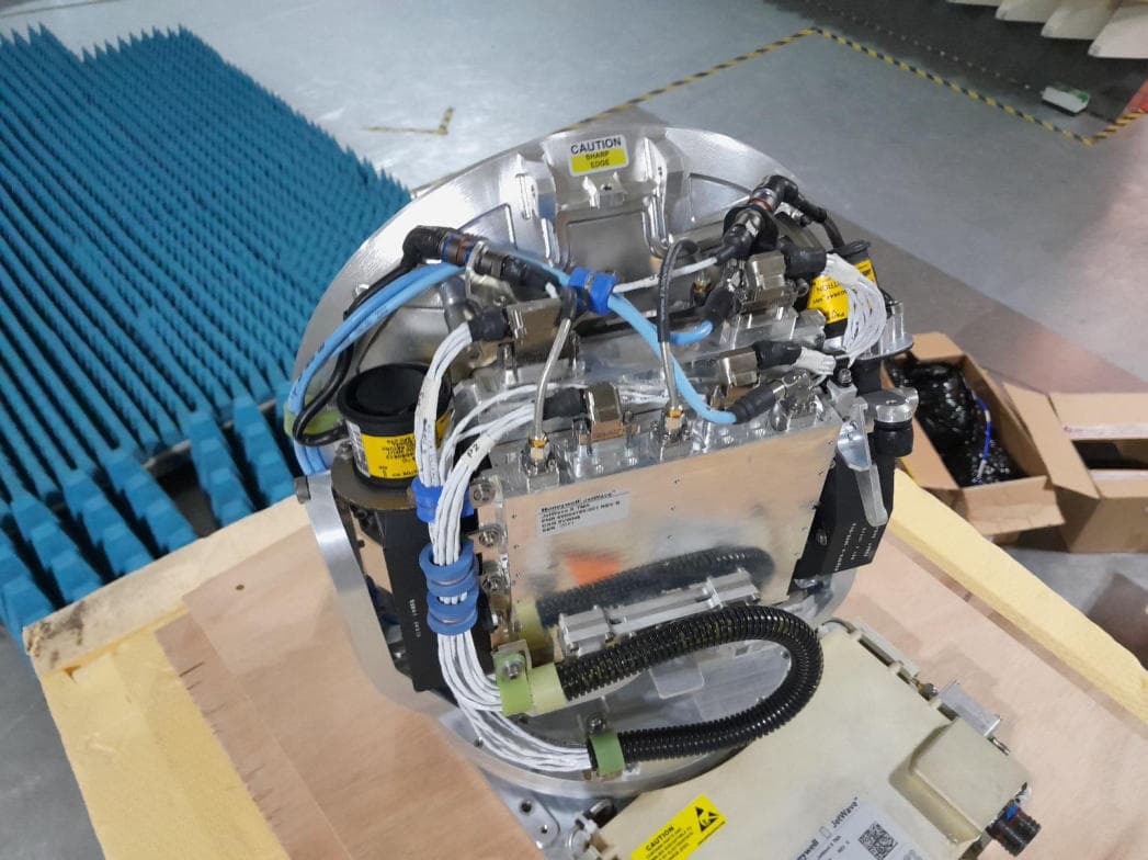
K6KJETWAVE4
Mar 09, 2026Jetwave X
Equipment Class
TNB - Licensed Non-Broadcast Station Transmitter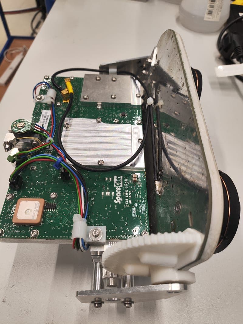
K6KSATCOM5G
Apr 17, 2024L Band SATCOM terminal with 5G cellular modem
Equipment Class
TNB - Licensed Non-Broadcast Station Transmitter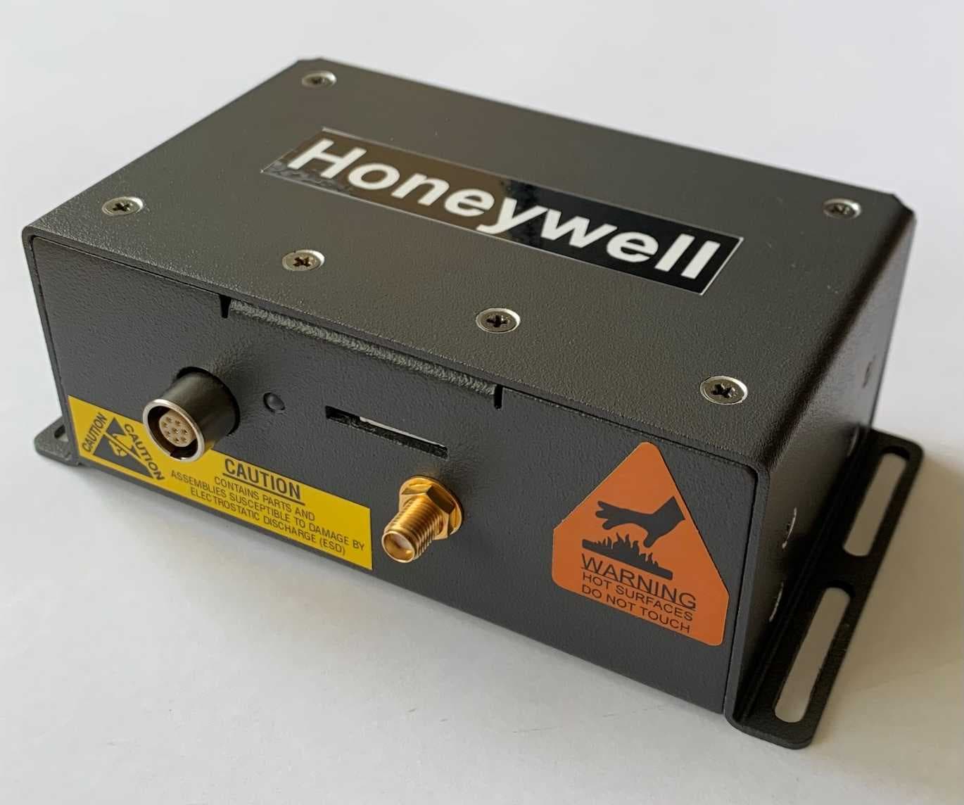
K6KSMALLSATCOM
May 16, 2021Small UAV Satcom
Equipment Class
TNB - Licensed Non-Broadcast Station Transmitter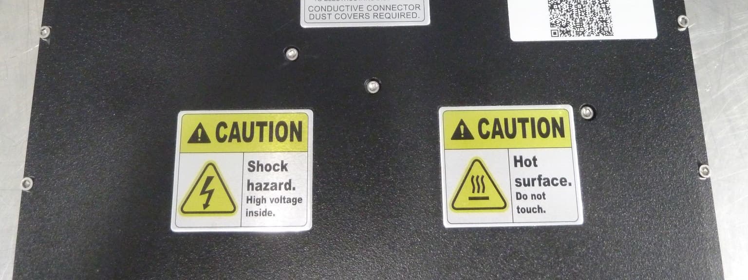
K6KJETWAVE3
Dec 22, 2020Jetwave
Equipment Class
TNB - Licensed Non-Broadcast Station Transmitter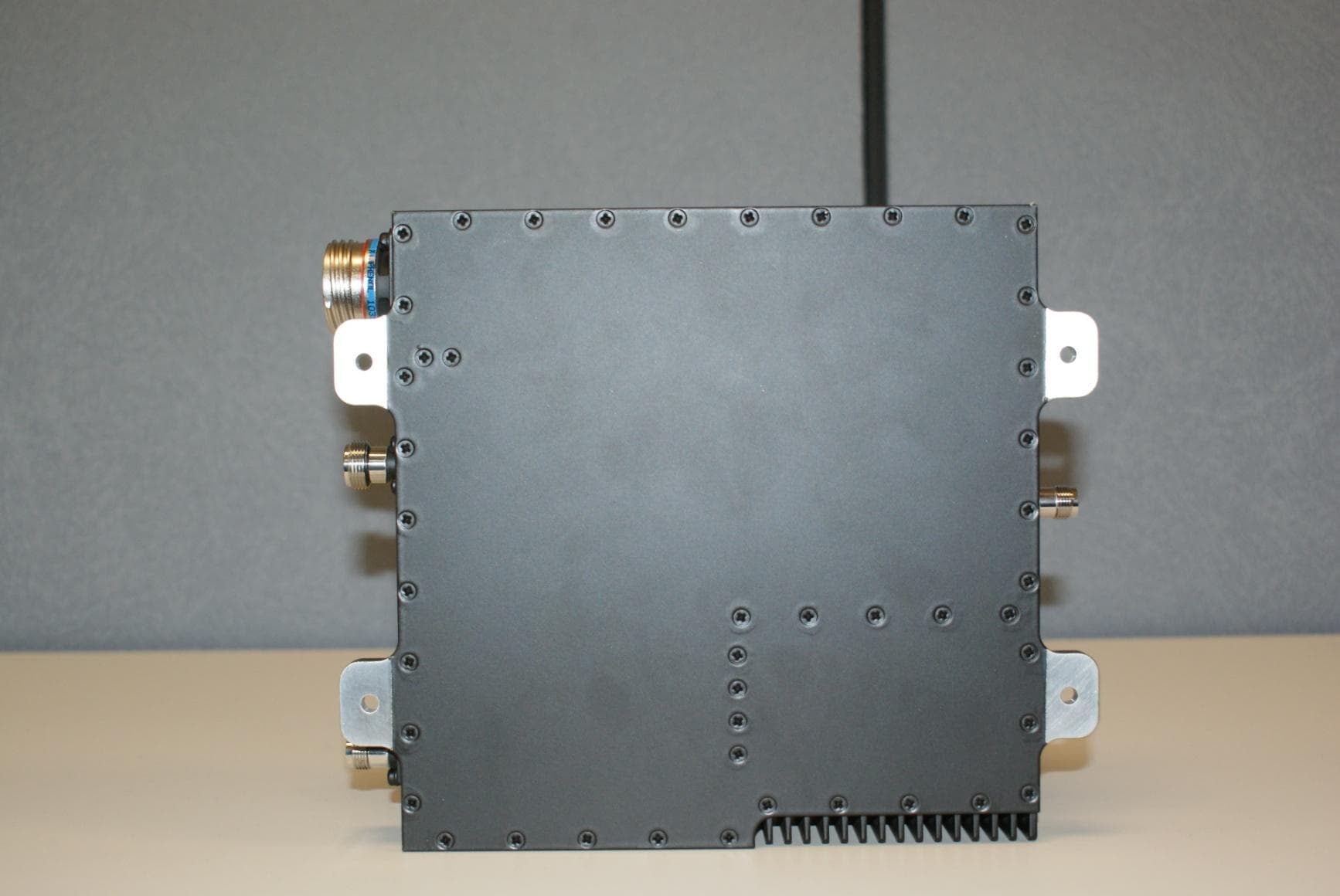
K6KIPLD
Sep 17, 2020Aircraft Earth Station
Equipment Class
TNB - Licensed Non-Broadcast Station Transmitter