K7SAV55000Wireless Video Adapter
Belkin International, Inc.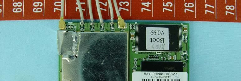
Click to zoom
Application Details
- Equipment Class
- NII - Unlicensed National Information Infrastructure TX
- Date of Grant
- Oct 12, 2004
- Application Purpose
- Original Equipment
- Date of Application
- Oct 12, 2004
- Equipment Note
- Wireless Video Adapter
- Frequency Range
- 5260.00000000 - 5320.00000000
- Company
- Belkin International, Inc.
- Country
- United States
Documents & Files
Document Text
Text extracted from the exhibit documents filed with the FCC. Open a document above to read the original.
Users Manual
User Manual RemoteTV ™ 5GHz Wireless TV Adapter Transmit high-quality audio video wirelessly to a TV in another room PureAV RemoteTV Table of Contents 1 Page Introduction ......................................................................................... 2 Benefits ....................................................................................3 Package Contents ...................................................................4 System Application Diagram .........................................................5 Transmitter and Receiver Details .................................................6 Front Panel ...............................................................................6 Rear Panel ................................................................................7 Installation Using Local Display ...............................................8-9 Installation without Local Display ..........................................10-11 Installation ......................................................................................12 Frequently Asked Questions ........................................................13 Specifications ................................................................................14 PureAV Power Protection .............................................................15 Information ...............................................................................16-18 Introduction PureAV RemoteTV Congratulations and thank you for purchasing the PureAV RemoteTV. This product delivers superior-quality MPEG-2 audio video in two rooms at once through the 5GHz frequency range, without interruption, so you can experience home entertainment like never before. Now you can view your favorite movies anywhere in your home without the hassle of running cables or moving media players from room to room. PureAV RemoteTV delivers the quality, ease of use, and freedom you need. Please review this User Manual carefully to ensure you enjoy the superior home entertainment experience PureAV offers. This package consists of two primary pieces—the PureAV RemoteTV Transmitter (the Transmitter) and the PureAV RemoteTV Receiver (the Receiver). The Transmitter sends audio and video from a source component, such as a cable box, satellite receiver, digital video recorder, or DVD/CD player to the Receiver, which is connected to a receiving component, such as a TV, LCD, or plasma display. The Transmitter converts analog input into high-quality digital MPEG-2 transport streams, which are transmitted wirelessly to the Receiver. The Receiver decodes the digital MPEG-2 stream and converts it to the analog format to display on an audio video device. Our Remote Control Extender lets you use an existing remote to control your video source in the other room. This saves you the hassle of walking back and forth and the expense of buying a separate remote. 2 PureAV RemoteTV Benefits • Provides long reach between Transmitter and Receiver for full-house coverage up to 350 ft. or 106m (subject to change due to environment) • Provides uninterrupted service and optimal resolution utilizing proprietary wireless technology to reduce interference and deliver up to 40Mbps of bandwidth—far exceeding the performance of the average wireless audio video sender • Incorporates component-video connectivity option for obtaining optimal resolution and brighter, more accurate movies and programs • Delivers superior video quality using MPEG-2 technology in both the encoder/Transmitter and decoder/Receiver • Allows use of an existing remote to control the video source in one room from a receiving source in the other room with the included Remote Control Extender (IR pass-through device) • Contains integrated antennas; requires no external antennas • Thwarts viewing by unauthorized receivers with 3DES content encryption • Supports NTSC video format • Supports standard-definition TV (SDTV) at full D1 MP@ML levels • Connects to TV via AV or SV terminal • Installs easily; simply plug in audio and video cables and go* *For optimal performance, we recommend upgrading your cables to premium PureAV Silver Series RCA Audio and Component Video Cables. PureAV Interconnects are designed to deliver the full potential of your home theater components, and capture the true sound and image experience of today’s high-tech music and movies. Component Video separates color into its primary components using three cables to transmit three distinct signals. This provides brighter, more accurate colors and sharper detail. If your equipment does not have a Component Video option, upgrade to S-Video. S-Video separates brightness from color using two separate conductors to create clean, accurate video reproduction, exceeding the performance of Composite Video. 3 PureAV RemoteTV Package Contents • One PureAV RemoteTV Transmitter • One PureAV RemoteTV Receiver • Two RCA Audio Video Cables • Two 5VDC Adapters • One PureAV Remote Control Extender (IR adapter) • User Manual 4 PureAV RemoteTV System Application Diagram 5 Following are two types of connections that can be made using the PureAV RemoteTV. a) A single audio video stream sent wirelessly to a single receiver. b) A single audio video stream sent wirelessly to a single receiver while connected to a local display. ���������� ����������������������������� ���������� ���������� ���������� ������������������� Transmitter and Receiver Details PureAV RemoteTV 6 ����� ����� ���� ����� ������ ���������������������� ������������������ ���������������������������� �������������� ������������ ���������������������� ���������������������� �������������������� ���������������� ��������� TransmitterReceiver This section describes the front and rear panels of the PureAV RemoteTV Transmitter and RemoteTV Receiver. Front Panel PureAV RemoteTV Transmitter and Receiver Details 7 S-Video Output Component-Video Output Composite-Video Output Left/Right Audio Output ON/OFF Button DC-5V Inlet DC-5V I…
Text truncated - open the document above for the full version.
Cover Letter(s)
FCC ID: K7SAV55000 Report No. RF930909L03A Modular Approval Request Letter Advance Data Technology Oct. 07, 2004 Dear Application Examiner, Belkin Corporation’s WIRELESS VIDEO ADAPTER with FCC ID: K7SAV55000, would like to have your authorization as a full modular approval specific to the mobile device such as access point. The requirements of Public Notice DA00-1407 have been met and shown on the following statements. 1. “The modular transmitter must have its own RF shielding.”: The radio portion of this module has been shielded, please see exhibition External Photo. 2. “The modular transmitter must have buffered modulation/data inputs.” The EUT has buffered data inputs, it is integrated in chipMGS6218. 3. “The modular transmitter must have its own power supply regulation.” The chips IF converter and RF/IF converter which will influence the frequency radiation, have to be 2.89Vdc powered. The mini-pci interface provides 3.3VDC, so there are regulators in front of these chips, the part number of this regulator is TPS79401 4. “The modular transmitter must comply with the antenna requirements of section 15.203 and 15.204(C).” The EUT meets the FCC antenna requirements. The spurious emission, unique antenna connector and photo of antennas are shown in the test report. 5. “The modular transmitter must be tested in a stand-alone configuration” Due to the mini-pci card with brand Intel, and the model name WM3B2200BG is specified to the Laptop PC, the EUT is tested in full system configuration. Please see section Photographs of Test Configuration in the test report. 6. “The modular transmitter must be labeled with its own FCC ID number.” Please see exhibition Label Sample for the FCC ID of this module. And also in the exhibition Users Manual, there are instructions given to the OEM on how to label the end product. FCC ID: K7SAV55000 Report No. RF930909L03A 7. “The modular transmitter must comply with any specific rule or operating requirements applicable to the transmitter and the manufacturer must provide adequate instructions along with the module to explain any such requirements.” The EUT is compliant with all applicable FCC rules. Detail instructions for maintaining compliance are given in the Users Manual. 8. “The modular transmitter must comply with any applicable RF exposure requirements.” The EUT is compliant with all applicable RF exposure requirements. RF Exposure is addressed in the RF exposure exhibition. Please contact me if you have any further questions. Thanks for your attention. Best Regards, Cody Chang / Deputy Manager Advance Data Technology
Cover Letter(s)
American Telecommunications Certification Body Inc. 6731 Whittier Ave, McLean, VA 22101 October 10, 2004 RE: Belkin Corporation FCC ID: K7SAV55000 After a review of the submitted information, I have a few comments on the above referenced Application. 1) The FRN provided does not appear to match any manufacture. Please check. Note that a grant can not be issued without a proper FRN number. 2) This device appears to contain multiple antennas. Please confirm how many antennas are used for TX and how many are used for Rx. 3) It is uncertain if the device may TX on multiple antennas at the same time. Please explain if the device may TX on multiple antennas at the same time. If so, this would likely be considered MIMO (multiple input/multiple output) technology. If considered as MIMO, this would require certification by the FCC since it would be considered new technology. 4) The label placed on the outside of the end device should contain the words “Contains”. However, the label applied directly to the mini-PCI module should not. Please correct. 5) Page 20 of the test report shows 8480 MHz as a restricted band, but does not provide average data to show compliance to 54 dBuV/m. Timothy R. Johnson Examining Engineer mailto: [email protected] The items indicated above must be submitted before processing can continue on the above referenced application. Failure to provide the requested information may result in application termination. Correspondence should be considered part of the permanent submission and may be viewed from the Internet after a Grant of Equipment Authorization is issued. Please do not respond to this correspondence using the email reply button. In order for your response to be processed expeditiously, you must submit your documents through the AmericanTCB.com website. Also, please note that partial responses increase processing time and should not be submitted. Any questions about the content of this correspondence should be directed to the sender.
Cover Letter(s)
Dear Tim Our client confirms there are just one PCB antenna is fixed to use for transmission. And the 731 form, label and test report have been revised today. Please check and really need your help to send the grant today. Thanks for your assistance! Best Regards Wendy Liao Page 1 of 1In 10/12/2004Printed for "Timothy R. Johnson" <[email protected]>
External Photos
Page 1 CONSTRUCTION PHOTOS OF EUT Page 2
ID Label/Location Info
FCC ID Label Location
Internal Photos
Page 3 Page 4
Operational Description
FCC ID: K7SAV55000 Report No.RF930909L03A Technical Description The transmitter of the EUT is powered from AC adapter. The antenna is PCB antenna with UFL antenna connector. Under normal use condition, the user has to keep at least 20cm separation distance between radiator and the body of the user. For more detailed instruction, please take a look at the user’s manual. FCC 15.407(c) states: The device shall automatically discontinue transmission in case of either absence of information to transmit or operational failure. These provisions are not intended to preclude the transmission of control or signaling information or the use of repetitive codes used by certain digital technologies to complete frame or burst intervals. Applicants shall include in their application for equipment authorization a description of hoe this requirement is met” Data transmission is always initiated by software, which is then pass down through the MAC, through the digital and analog baseband, and finally to the RF chip. Several special packets (ACKs, CTS, PSPoll, etc...) are initiated by the MAC. There are the only ways the digital baseband portion will turn on the RF transmitter, which it then turns off at the end of the packet. Therefore, the transmitter will be on only while one of the aforementioned packets are being transmitted.
RF Exposure Info
Report No: RF930909L03A 1 RF EXPOSURE REPORT REPORT NO.: RF920909L03A MODEL NO.: AV55000 ACCORDING: FCC Guidelines for Human Exposure IEEE C95.1 APPLICANT: Belkin Corporation ADDRESS: 501 West Walnut Street Compton, CA90220- 5221, U.S.A. ISSUED BY: Advance Data Technology Corporation TEST LOCATION: No. 19, Hwa Ya 2nd Rd., Wen Hwa Tsuen, Kwei Shan Hsiang, Taoyuan Hsien 333, Taiwan, R.O.C. Report No: RF930909L03A 2 RF Exposure Measurement (Mobile Device) 1. Introduction In this document, we try to prove the safety of radiation harmfulness to the human body for our product. The limit for Maximum Permissible Exposure (MPE) specified in FCC 1.1310 is followed. The Gain of the antenna used in this product is measured in a Fully Anechoic Chamber (FAC) calibrated for antenna measurement in ADT, and also the maximum total power input to the antenna is measured. Through the Friis transmission formula and the maximum gain of the antenna, we can calculate the distance, away from the product, where the limit of MPE is reached. Although the Friis transmission formula is a far field assumption, the calculated result of that is an over-prediction for near field power density. We will take that as the worst case to specify the safety range. 2. RF Exposure Limit According to FCC 1.1310: The criteria listed in the following table shall be used to evaluate the environmental impact of human exposure to radio-frequency (RF) radiation as specified in 1.1307(b) LIMITS FOR MAXIMUM PERMISSIBLE EXPOSURE (MPE) Frequency Range (MHz) Electric Field Strength (V/m) Magnetic Field Strength (A/m) Power Density (mW/cm 2 ) Average Time (minutes) (A)Limits For Occupational / Control Exposures 300-1500......F/3006 1500-100,000......56 (B)Limits For General Population / Uncontrolled Exposure 300-1500......F/15006 1500-100,000......1.030 F = Frequency in MHz Report No: RF930909L03A 3 3. Friis Formula Friis transmission formula : Pd = (Pout*G) / (4*pi*r 2 ) where Pd = power density in mW/cm 2 Pout = output power to antenna in mW G = gain of antenna in linear scale Pi = 3.1416 R = distance between observation point and center of the radiator in cm If we know the maximum Gain of the antenna and the total power input to the antenna, through the calculation, we will know the MPE value at distance 20cm. Ref. : David K. Cheng, Field and Wave Electromagnetics, Second Edition, Page 640, Eq. (11-133). 4 EUT Operating condition The software provided by Manufacturer enabled the EUT to transmit and receive data at lowest, middle and highest channel individually. 5. Classification The antenna of this product, under normal use condition, is at least 20cm away from the body of the user. Warning statement to the user for keeping at least 20cm or more separation distance with the antenna should be included in users manual. So, this device is classified as Mobile Device. Report No: RF930909L03A 4 6 Test Results 6.1 Antenna Gain The maximum Gain measured in Fully Anechoic Chamber are 5.0dBi or 3.162 (numeric). 6.2 Output Power Into Antenna & RF Exposure value at distance 20cm: Channel Channel Frequency (MHz) Output Power to Antenna (mW) Power Density (mW/cm 2 ) Limit of Power Density (mW/cm 2 ) 1 5180 31.842 0.0200 1.0 4 5240 28.642 0.0180 1.0 55260 28.249 0.01781.0 8 5320 17.906 0.0113 1.0
Test Report
FCC ID: K7SAV55000 Report No.: RF930909L03A1Issued: Oct. 06, 2004 FCC TEST REPORT REPORT NO.: RF930909L03A MODEL NO.: AV55000 RECEIVED: Sep. 08, 2004 TESTED: Sep. 08 ~ Sep. 29, 2004 APPLICANT: Belkin Corporation ADDRESS: 501 West Walnut Street Compton, CA90220- 5221, U.S.A. ISSUED BY: Advance Data Technology Corporation LAB ADDRESS: No. 47, 14th Ling, Chia Pau Tsuen, Lin Kou Hsiang 244, Taipei Hsien, Taiwan, R.O.C. TEST LOCATION: No. 19, Hwa Ya 2nd Rd., Wen Hwa Tsuen, Kwei Shan Hsiang, Taoyuan Hsien 333, Taiwan, R.O.C. This test report consists of 64 pages in total. It may be duplicated completely for legal use with the approval of the applicant. It should not be reproduced except in full, without the written approval of our laboratory. The client should not use it to claim product endorsement by CNLA, A2LA or any government agencies. The test results in the report only apply to the tested sample. 0528 ILAC MRA FCC ID: K7SAV55000 Report No.: RF930909L03A2Issued: Oct. 06, 2004 Table of Contents 1.CERTIFICATION ......................................................................................................4 2.SUMMARY OF TEST RESULTS ..............................................................................5 2.1MEASUREMENT UNCERTAINTY ...........................................................................5 3.GENERAL INFORMATION.......................................................................................6 3.1GENERAL DESCRIPTION OF EUT.........................................................................6 3.2DESCRIPTION OF TEST MODES...........................................................................7 3.3GENERAL DESCRIPTION OF APPLIED STANDARDS ..........................................7 3.4DESCRIPTION OF SUPPORT UNITS .....................................................................7 3.5CONFIGURATION OF SYSTEM UNDER TEST ......................................................7 4.TEST TYPES AND RESULTS ..................................................................................8 4.1CONDUCTED EMISSION MEASUREMENT ...........................................................8 4.1.1 LIMITS OF CONDUCTED EMISSION MEASUREMENT......................................... 8 4.1.2 TEST INSTRUMENTS.............................................................................................. 8 4.1.3 TEST PROCEDURES .............................................................................................. 9 4.1.4 DEVIATION FROM TEST STANDARD .................................................................... 9 4.1.5 TEST SETUP ......................................................................................................... 10 4.1.6 EUT OPERATING CONDITIONS ........................................................................... 10 4.1.7 TEST RESULTS ..................................................................................................... 11 4.2RADIATED EMISSION MEASUREMENT ..............................................................13 4.2.1 LIMITS OF RADIATED EMISSION MEASUREMENT............................................ 13 4.2.2 LIMITS OF UNWANTED EMISSION OUT OF THE RESTRICTED BANDS .......... 14 4.2.3 TEST INSTRUMENTS............................................................................................ 15 4.2.4 TEST PROCEDURES ............................................................................................ 16 4.2.5 DEVIATION FROM TEST STANDARD .................................................................. 16 4.2.6 TEST SETUP ......................................................................................................... 17 4.2.7 EUT OPERATING CONDITIONS ........................................................................... 17 4.2.8 TEST RESULTS ..................................................................................................... 18 4.3PEAK TRANSMIT POWER MEASUREMENT .......................................................24 4.3.1 LIMITS OF PEAK TRANSMIT POWER MEASUREMENT..................................... 24 4.3.2 TEST INSTRUMENTS............................................................................................ 24 4.3.3 TEST PROCEDURE............................................................................................... 25 4.3.4 DEVIATION FROM TEST STANDARD .................................................................. 25 4.3.5 TEST SETUP ......................................................................................................... 25 4.3.6 EUT OPERATING CONDITIONS ........................................................................... 25 4.3.7 TEST RESULTS ..................................................................................................... 26 4.4PEAK POWER EXCURSION MEASUREMENT ....................................................35 4.4.1 LIMITS OF PEAK POWER EXCURSION MEASUREMENT.................................. 35 4.4.2 TEST INSTRUMENTS............................................................................................ 35 4.4.3 TEST PROCEDURE............................................................................................... 36 4.4.4 DEVIATION FROM TEST STANDARD .................................................................. 36 4.4.5 TEST SETUP ......................................................................................................... 36 4.4.6 EUT OPERATING CONDITIONS ........................................................................... 36 FCC ID: K7SAV55000 Report No.: RF930909L03A3Issued: Oct. 06, 2004 4.4.7 TEST RESULTS ..................................................................................................... 37 4.5PEAK POWER SPECTRAL DENSITY MEASUREMENT ......................................42 4.5.1 LIMITS OF PEAK POWER SPECTRAL DENSITY MEASUREMENT.................... 42 4.5.2 TEST INSTRUMENTS..............................................................................…
Text truncated - open the document above for the full version.
Test Setup Photos
FCC ID: K7SAV55000 Report No.: RF930909L03A60Issued: Oct. 06, 2004 5. PHOTOGRAPHS OF THE TEST CONFIGURATION CONDUCTED EMISSION TEST FCC ID: K7SAV55000 Report No.: RF930909L03A61Issued: Oct. 06, 2004 FCC ID: K7SAV55000 Report No.: RF930909L03A62Issued: Oct. 06, 2004 RADIATED EMISSION TEST FCC ID: K7SAV55000 Report No.: RF930909L03A63Issued: Oct. 06, 2004
Contact Information
Applicant
Jay TU(Manager, Regulatory Compliance)
Technical Contact
Advance Data Technology CorporationEllis Wu
[email protected]+886-3-318-3232
No. 19 Hwa Ya 2nd rd. · Kueishan Taoyuan · Taiwan
Non-Technical Contact
Advance Data Technology CorporationEllis Wu
[email protected]+886-3-318-3232
Test Firm
Bureau Veritas CPS (H.K.) Ltd. Taoyuan BranchTommy Wu
Technical Specifications
| # | Rule Parts | Frequency Range | Power Output |
|---|---|---|---|
| 2 | 15E | 5.26 GHz - 5.32 GHz | 28.00 mW |
Other Applications from Belkin International, Inc.
K7S-CAB029
Aug 11, 2026SureFind Loop Cable Tag
Equipment Class
DTS - Digital Transmission SystemK7SBPD024
Aug 10, 2026UltraCharge Pro Slim Magnetic Power Bank 5K with BoostSolid Cell
Equipment Class
DCD - Part 15 Low Power Transmitter Below 1705 kHzK7SMMA016
Jul 22, 2026SureFind Wallet Stand
Equipment Class
DTS - Digital Transmission SystemK7SMMA015
Jul 10, 2026SureFind
Equipment Class
DTS - Digital Transmission SystemK7SAUC018
Jun 17, 2026SoundForm Dot ANC Earbuds, SoundForm Dot Earbuds
Equipment Class
DTS - Digital Transmission System