K7SF1DG102WComputing Device Peripheral
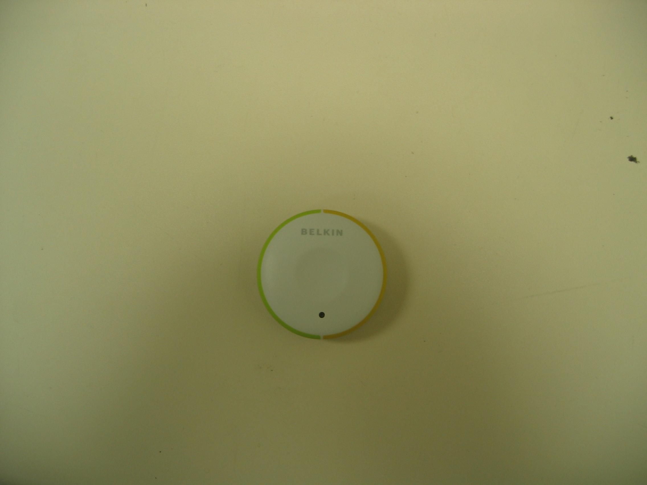
Belkin International, Inc.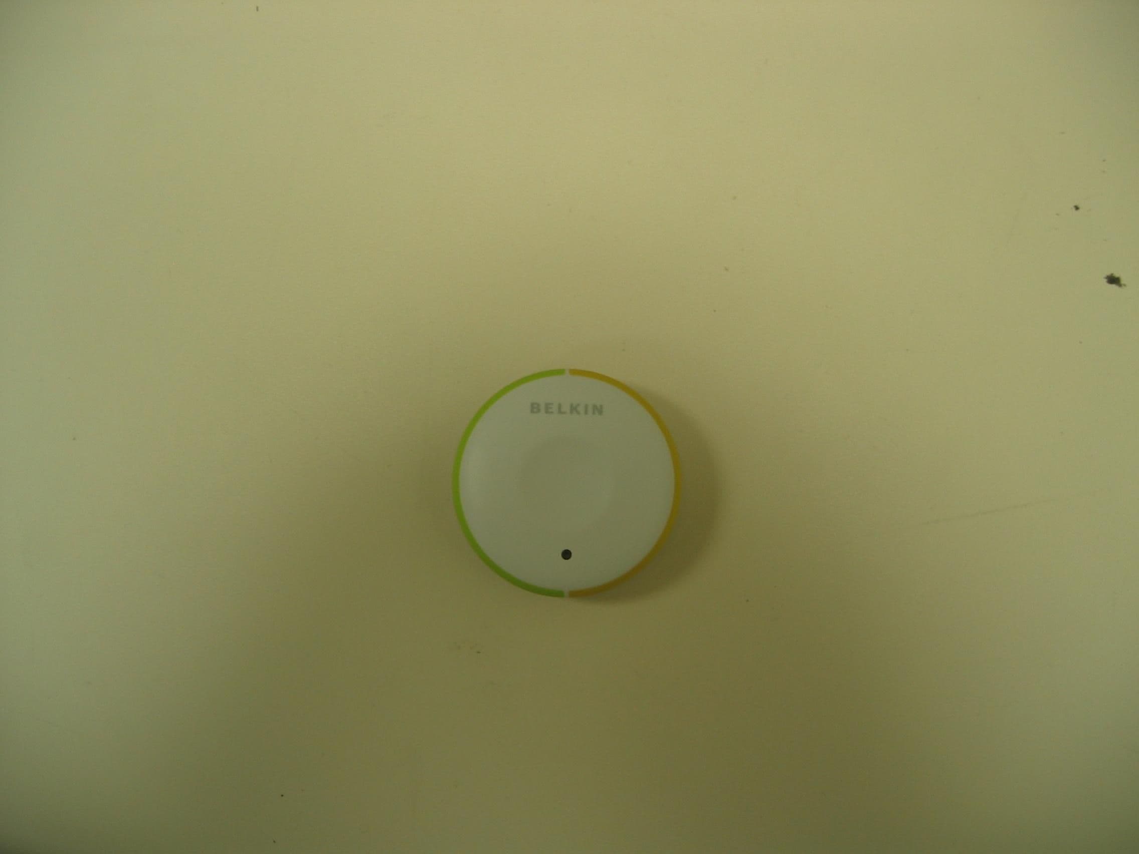
Click to zoom
Application Details
- Equipment Class
- DSC - Part 15 Security/Remote Control Transmitter
- Date of Grant
- Jun 20, 2006
- Application Purpose
- Original Equipment
- Date of Application
- Jun 20, 2006
- Equipment Note
- Computing Device Peripheral
- Frequency Range
- 433.91000000 - 433.91000000
- Company
- Belkin International, Inc.
- Country
- United States
Documents & Files
Document Text
Text extracted from the exhibit documents filed with the FCC. Open a document above to read the original.
Users Manual
System Requirements Monitor Flip supports any monitor with a VGA connection. You can also use your DVI-I monitor with Flip by connecting a VGA adapter to the DVI cable. Flip does not support direct DVI connections from monitors. Keyboard/Mouse Flip supports any keyboard and mouse with a USB connection. Computers Flip can be used with any PC or Mac ® desktop or notebook computer that supports USB keyboard and mouse connections, and that runs on one of these operating systems: • Windows ® 98 SE, 2000, XP, 2003 • Mac OS ® X v10.0 and above • Linux ® Package Contents • Wireless Remote • Base with Cables • Audio Extension Cable • Fastener Strip • Battery Introduction Congratulations and thank you for purchasing Flip Wireless. Flip is easy to set up and use, and comes with everything you need to share one monitor, keyboard, mouse, and one set of speakers between your two computers. No additional cables or software are required. The diagram below shows a typical Flip Wireless setup. The wireless remote sits on your desk. Your monitor, keyboard, mouse, and speakers plug into the base, and the base connects to your two computers through the attached cables. Installing your Flip Before you begin, make sure that your USB keyboard and mouse work properly with both computers. 1. Power on your computers. 2. Connect your monitor, keyboard, mouse, and speakers to the base. Insert the battery into the wireless remote (positive side facing out), and place the remote anywhere on your desk within 10 feet of the base. 3. Connect one set of cables to the monitor, USB, and speaker ports on your first computer. Wait for your computer to recognize the new USB device (Flip). Then connect the other set of cables to the monitor, USB, and speaker ports on your second computer. If the cable is not long enough to connect to your speaker port, use the included audio extension cable. You are now ready to use your Flip. Flip Tip: Use the included fastener strip to attach the remote to your monitor, keyboard, desk, or other item. Flip Tip: Keep the base behind your computers to keep your desk free of cable clutter. Package Contents/Introduction 1System Requirements 2Installing your Flip 3Installing your Flip 4 Using your Flip When you power up your computers, your first computer’s desktop will appear on your monitor. You are now ready to use that computer as if it were directly connected to your monitor, keyboard, mouse, and speakers. To switch access to your other computer, simply press the remote. Your other computer’s desktop will appear on your monitor. You are now ready to use your other computer as if it were directly connected to your monitor, keyboard, mouse, and speakers. Press the remote each time you want to switch access from one computer to the other. Optional Software You can install software onto your computers that will allow you to flip between computers using a desktop icon or keyboard hot-key sequence. The software will also allow you to listen to music files on one computer while you work on the other. To download the free software, please visit our website at www.belkin.com/flip. Note: For a list of frequently asked questions and troubleshooting tips, please visit our website at www.belkin.com/flip. Using your Flip 5 USB connection VGA connection User Guide F1DG102W Information FCC Statement DECLARATION OF CONFORMITY WITH FCC RULES FOR ELECTROMAGNETIC COMPATIBILITY We, Belkin Corporation, of 501 West Walnut Street, Compton CA 90220, declare under our sole responsibility that the product F1DG102W, to which this declaration relates: Complies with Part 15 of the FCC Rules. Operation is subject to the following two conditions: (1) this device may not cause harmful interference, and (2) this device must accept any interference received, including interference that may cause undesired operation. Changes or modifications not expressly approved by the party responsible for compliance could void the user’s authority to operate the equipment. CE Declaration of Conformity We, Belkin Corporation, declare under our sole responsibility that the F1DG102W, to which this declaration relates, is in conformity with Emissions Standard EN55022 and with Immunity Standard EN55024, LVP EN61000-3-2, and EN61000-3-3. ICES This Class B digital apparatus complies with Canadian ICES-003. Cet appareil numérique de la classe B est conforme á la norme NMB-003 du Canada. Belkin Corporation Limited 3-Year Product Warranty What this warranty covers. Belkin Corporation warrants to the original purchaser of this Belkin product that the product shall be free of defects in design, assembly, material, or workmanship. What the period of coverage is. Belkin Corporation warrants the Belkin product for three years. What will we do to correct problems? Product Warranty. Belkin will repair or replace, at its option, any defective product free of charge (except for shipping charges for the product). Belkin Corporation 501 West Walnut Street Los Angeles, CA 90220-5221, USA 310-898-1100 310-898-1111 fax Belkin Ltd. Express Business Park, Shipton Way Rushden, NN10 6GL, United Kingdom +44 (0) 1933 35 2000 +44 (0) 1933 31 2000 fax Belkin Ltd. 7 Bowen Crescent, West Gosford NSW 2250, Australia +61 (0) 2 4372 8600 +61 (0) 2 4372 8603 fax Belkin B.V. Boeing Avenue 333 1119 PH Schiphol-Rijk, The Netherlands +31 (0) 20 654 7300 +31 (0) 20 654 7349 fax Belkin Tech Support US: 800-223-5546 ext. 2263 310-898-1100 ext. 2263 Europe: 00 800 223 55 460 Australia: 1800 235 546 New Zealand: 0800 235 546 Singapore: 800 616 1790 © 2006 Belkin Corporation. All rights reserved. All trade names are registered trademarks of respective manufacturers listed. Mac and Mac OS are trademarks of Apple Computer, Inc., registered in the U.S. and other countries. Windows is either a registered trademark or trademark of Microsoft Corporation in the United States and/or other countries. Information 7 What is not covered by this warranty? All above warranties are null and void if the …
Text truncated - open the document above for the full version.
Cover Letter(s)
501W.WalnutStreet- Compton- California90220USA May31,2006 FederalCommunicationsCommission EquipmentApprovalServices P.O.Box358315 Pittsburgh,PA15251-5315 USA FCCID:K7SFlDGI02W ToWhomIt MayConcern: Werequestunder47CFR0.459and47CFR0.457thatmaterialssubmittedtotheTelecommunications CertificationBodybewithheldfrompublicinspection. Specifically,BelkinCorporationrequeststhatthefollowingmaterialsbewithheldfrompublicinspectionunder 47CFR0.459and47CFR0.457becausetheyareconfidentialtradesecretsandtechnicaldatawhichwouldbe guardedfromcompetitors. (1)Detailedcircuitschematicofunitundertest (2)Partslist (3)Blockdiagram Therefore,inaccordancewith47CFR0.459and47CFR0.457werequestthattheabovelistedmaterials,copies ofwhichareattachedhere,bewithheldfrompublicinspection. MarcMatejka EngineeringServicesManager
Cover Letter(s)
Non-Conformities FCC ID: K7SF1DG102W (Ref # E06-000163-1) OK # Non-Conformity or Comment Submitted Response Respondent / Date of Response X 1 Please provide test setup photos as a separate exhib it. Separate exhibits uploaded. Belkin 6/15/06 X 2 In accordance with 2.1033(b)(5), Please supply a block diagram showing the frequency of all oscillators in the device. Updated block diagram pr ovided. Belkin 6/19/06 X 3 In accordance with 2.1033(b)(7), Please provide updated internal photos showing all sides of the PCB in sufficient detail to read the silkscreen. Updated internal photos provided Belkin 6/19/06 X 4 Please provide additional external photos of the back of th e enclosure. Updated external photos provided Belkin 6/19/06 X 5 Please provide FCC ID label information including a photo or drawing of the ID label and an exhibit showing label placement. Updated ID label exhibit provided Belkin 6/19/06 X 6 Please provide a users manual incorporating the statement required by 15.21, “Changes or modifications not expressly approved by the party responsible for compliance could void the user's authority to operate the equipment” Updated users manual provided. Belkin 6/16/06 X 7 Equipment class JBP is reserved for part 15B computer peripherals. CKC CS suggests the use of DSC fo r the correct equipment class for the transmitter. “DSC-Part 15 Security/Remote Control Transmitter 15.231”. Please confirm whether this is correct. Equipment Class DSC confirmed. Belkin 6/14/06 X 8 Please confirm testing was performed in accordance with 15.31(e), ie. A fresh battery installed for testing. “In accordance with FCC 15.31(e) for intentional radiators, the Belkin Flip for PC, Wireless (S/N 72858) testing was performed using a new battery.” Belkin 6/15/06 X 9 Please confirm preliminary testing was performed in three orthogonal axis in accordance with ANSI C63.4 in order to determine orientation of maximum emissions. Confirmation obtained from test lab. Belkin 6/20/06 X 10 Please provide demonstration of compliance to 15.231(a)(1), the device must cease operation within 5 seconds of the button being released. Additional information provided. Belkin 6/21/06 X 11 CKC CS to confirm FCC ID numbers are consistent Confirmed 6/19/06 X 12 CKC CS to confirm equipment class Confirmed. 6/14/06
Operational Description
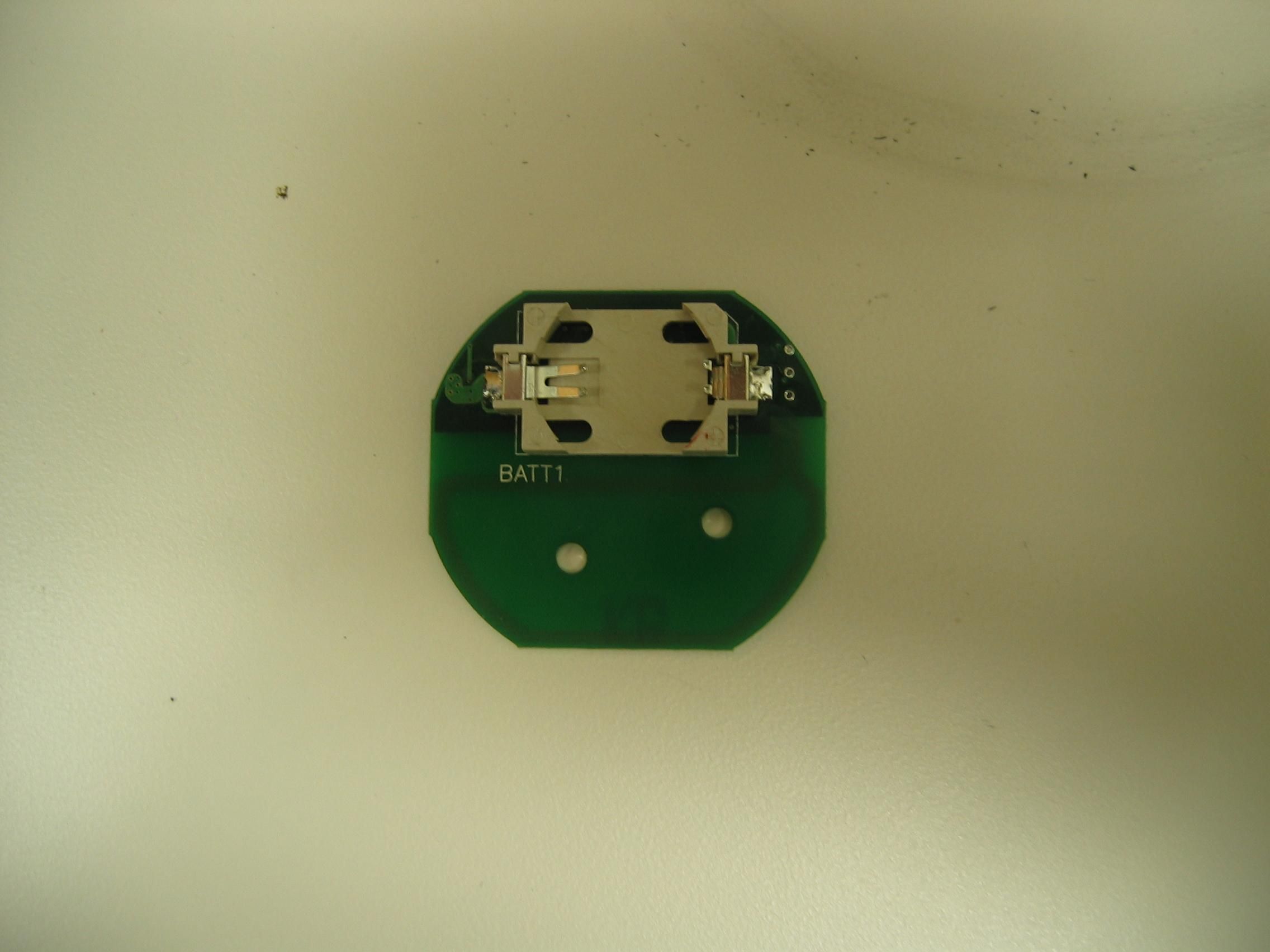
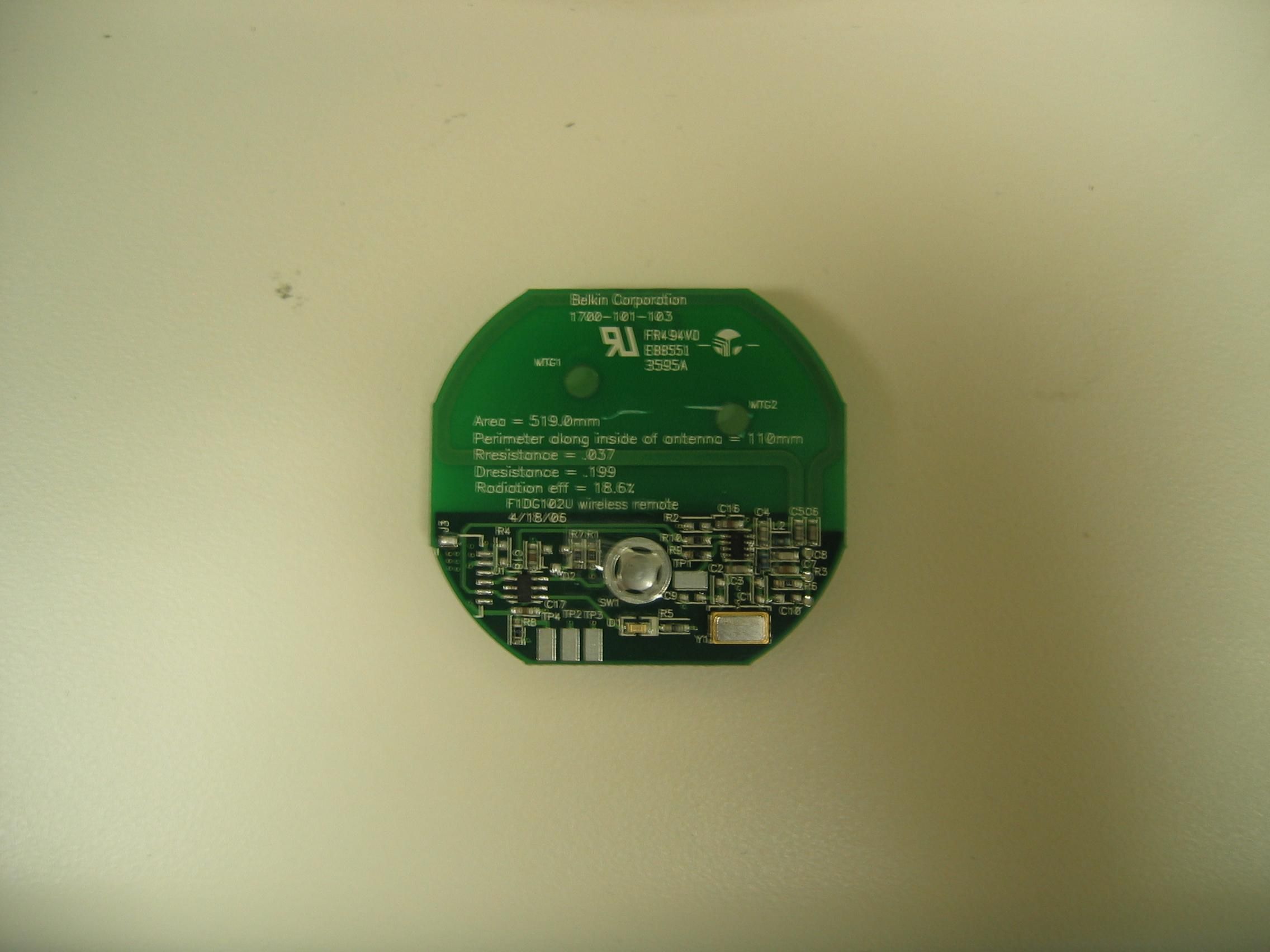
501 W. Walnut Street – Compton – California 90220 USA Operation Description: The F1DG102W is a 2 port switching device that switches Keyboard, mouse, and monitor outputs from one of two sources to a single synch. This enables a user to share the same Keyboard, Mouse and monitor between to computers. The F1DG102W main board draws its powered form the source computers USB ports. The power consumed from each port is 5V @ .5A. The switching mechanism is evoked in one of two manners. One is by means of software running on either of the source computers. Communication by the software is done through the USB connection between the KVM main board and the source computers. The second is by means of a RF remote. The RF remote is powered from a single 3.0V coin cell. The remote remains in a sleep state until it is awakened by detection of a mechanical button press. Upon detection of button press, a micro processor enables an ON/OFF keyed (OOK) modulated transmitter. The processor then sends the transmitter an Address and switch command in digital format at 1kbps rate. This digital signal is modulated by the transmitter and sent out as a 25ms burst of RF energy at 22uW, centered around 433.92MHZ. The transmitter is then disabled by the micro processor. The micro processor then flashes an LED indicating that an RF emission has taken place, after which the micro processor enters a sleep state and waits for another button press. The RF transmission is received at the KVM main board and demodulated. The KVM main board then performs a switch between the source computers.
Test Report
Figure 1. Shown in figure one above is two oscilloscope channels. Channel 2 shows a high to low transition, approximately 2.9Vdc to 0Vdc. This transition was caused by a user pressing the button on the remote. This transition was triggered on, as is indicated in the figure by the orange “T” in the upper left hand corner. Approximately 600usec after the trigger channel 1 is seen transitioning from 0Vdc to approximately 3Vdc. Channel 1 is the input enable on the MAX1492 ASK/OOK transmitter. As can be seen from the figure, for one button push the transmitter is enabled for 32msec, during which ON/OFF KEYING is used to modulate a “switch command” onto a 433.92MHz carrier.
Test Report
TEST SERVICES EMC EVALUATION OF THE BELKIN CORPORATION FLIP FOR PC, WIRELESS Date: MAY 26, 2006 Test Report Number: TRR0312.06 IN ACCORDANCE WITH FCC PART 15 SUBPART C 15.231 Prepared For: BELKIN CORPORATION 1057 EAST HENRIETTA ROAD ROCHESTER, NEW YORK 14623 ATTENTION: JACK PRIEBE Prepared By: MATTHEW HANEL CHOMERICS TEST SERVICES ROCHESTER FACILITY 100 INDIGO CREEK DRIVE ROCHESTER, NEW YORK 14626 WOBURN FACILITY 77 DRAGON COURT WOBURN, MASSACHUSETTS 01801 Test Technician or Engineer: _________________________ CTS Approved Signatory: _________________________ This report shall not be reproduced except in full without the written approval of Chomerics Test Services. TEST SERVICES Belkin Corporation Flip for PC, Wireless Document #: TRR0312.06 Date: May 26, 2006 Page 2 of 36 TABLE OF CONTENTS 1.0 General 1.1 Introduction 1.1.1 Purpose 1.1.2 Requirements 1.2 Test Summary 1.2.1 Summary of Recommendations 1.3 Administrative Data 1.3.1 Test Facility 1.3.2 Equipment Calibration 1.3.3 Test Personnel 1.4 Test Set-up 1.4.1 Test Site Matrix 1.4.2 Test Site Descriptions 1.4.3 Equipment Under Test 1.4.4 Block Diagram 2.0 Emissions Tests Performed 2.1 FCC Class B Subpart A Radiated Emissions (FCC 47 CFR 15.33) 2.1.1 Equipment Used 2.1.2 Test Conditions 2.1.3 Test Method 2.1.4 Results 2.1.5 Test Data 2.1.6 Photographic Documentation 2.2 FCC Class B Subpart C Radiated Emissions (FCC 47 CFR 15.209) 2.2.1 Equipment Used 2.2.2 Test Conditions 2.2.3 Test Method 2.2.4 Result 2.2.5 Test Data 2.2.6 Photographic Documentation 2.3 FCC Part 15 Subpart C Radiated Emissions (FCC 47 CFR 15.231) 2.3.1 Equipment Used 2.3.2 Test Conditions 2.3.3 Test Method 2.3.4 Result 2.3.5 Test Data 2.3.6 Photographic Documentation Appendix A: Test Log TEST SERVICES Belkin Corporation Flip for PC, Wireless Document #: TRR0312.06 Date: May 26, 2006 Page 3 of 36 LIST OF DEFINITIONS/ABBREVIATIONS AC Alternating Current BB Broadband BW Bandwidth cm Centimeter CPU Calibrate Prior to Use dB Decibel DC Direct Current EMC Electromagnetic Compatibility EMI Electromagnetic Interference ER Electric Radiation EUT Equipment Under Test GHz GigaHertz Hz Hertz I-face Interface kHz KiloHertz m Meter MHz MegaHertz mm Millimeter mS Millisecond mV MilliVolt MR Magnetic Radiation NB Narrowband NCR No Calibration Required PLC Power Line Conduction PPS Pulses Per Second uF MicroFarad uH MicroHenry uS Microsecond uV MicroVolt UWC Use With Calibrated Equipment TEST SERVICES Belkin Corporation Flip for PC, Wireless Document #: TRR0312.06 Date: May 26, 2006 Page 4 of 36 1.0 GENERAL 1.1 Introduction 1.1.1 Purpose The purpose of this report is to document the performance of the Belkin Corporation Flip for PC, Wireless during an electromagnetic interference (EMI) test and record the test requirements and procedures used. At the request of Belkin Corporation, the tests were performed by Chomerics Test Services (CTS) of Woburn, Massachusetts at Chomerics’ test facility located in Rochester, New York. The assessment will determine the compliance or non-compliance with the requirements set up by the FCC Part 15 Subpart C 15.231 Radio Frequency Devices – Intentional Transmitters – Periodic Operation in the band of 40.66 – 40.77 MHz and above 70 MHz. Jack Priebe from Belkin Corporation was present during testing. Testing was performed during the period of May 8, 12 and May 17, 19, 2006 under Belkin’s purchase order #122591. 1.1.2 Requirements The requirements for the sequence of tests performed on the Flip for PC, Wireless are as follows: FCC Part 15 Subpart A 15.33 FCC Part 15 Subpart A 15.33, Frequency Range of Radiated Measurements: For an intentional radiator, the spectrum shall be investigated from the lowest radio frequency signal generated in the device, without going below 9 kHz, up to at least the frequency shown in paragraph (1). If the intentional radiator operates below 10 GHz, emissions must be measured to the tenth harmonic of the highest fundamental or to 40 GHz, whichever is lower. TEST SERVICES Belkin Corporation Flip for PC, Wireless Document #: TRR0312.06 Date: May 26, 2006 Page 5 of 36 FCC Part 15 Subpart A 15.35 FCC Part 15 Subpart C 15.35, Measurement Detector Functions and Bandwidths: On any frequency or frequencies below or equal to 1000 MHz, the limits shown are based on measuring equipment employing a CISPR quasi-peak detector function and related measurement bandwidths, unless otherwise specified. The specifications for the measuring instrument used were in accordance with CISPR 16. Peak detector measured data may be substituted for the appropriate detector data to show compliance if the peak level obtained does not exceed the limit. The bandwidth used shall be greater than or equal to 100 Hz from 9 kHz to 150 kHz, 9 kHz from 150 kHz to 30 MHz and 100 kHz from 30 MHz to 1000 MHz. Actual Bandwidths used: 1 – 30 MHz; 9 kHz 30 – 1000 MHz; 120 kHz > 1000 MHz; 1 MHz FCC Part 15 Subpart C 15.205 FCC Part 15 Subpart C 15.205, Restricted Bands of Operation: Sec. 15.205: Only spurious emissions are permitted in the frequency bands listed in paragraph (a) of this document. The field strength of emissions appearing within these frequency bands shall not exceed the limits shown in Sec 15.209. At frequencies equal to or less than 1000 MHz, compliance with the limits in Sec. 15.209 shall be demonstrated using measurement instrumentation employing a CISPR quasi-peak detector. Above 1000 MHz, compliance with the emissions limits in Sec. 15.209 shall be demonstrated based on the average value of the measured emissions. The provisions of Sec. 15.35 apply to these measurements. FCC Part 15 Subpart C 15.209 FCC Part 15 Subpart C 15.209, Radiated Emission; General Requirements: Sec. 15.209: Emissions from the intentional radiator shall not exceed the field strength levels given in paragraph (a) of this document. The level of any unwanted emissions from an intentional radiator operating under these general provisions shall not exceed the level of the fundamental …
Text truncated - open the document above for the full version.
Contact Information
Applicant
Jay TU(Manager, Regulatory Compliance)
Technical Contact
Belkin CorporationMarc Matejka
[email protected]310-604-2448
501 W. Walnut Street · Compton, California · United States
Test Firm
Parker Hannifin Chomerics Test Services-Woburn, MADavid Inman
Technical Specifications
| # | Rule Parts | Frequency Range | Power Output |
|---|---|---|---|
| 1 | 15.231 | 433.91 MHz - 433.91 MHz | - |
Other Applications from Belkin International, Inc.
K7S-CAB029
Aug 11, 2026SureFind Loop Cable Tag
Equipment Class
DTS - Digital Transmission SystemK7SBPD024
Aug 10, 2026UltraCharge Pro Slim Magnetic Power Bank 5K with BoostSolid Cell
Equipment Class
DCD - Part 15 Low Power Transmitter Below 1705 kHzK7SMMA016
Jul 22, 2026SureFind Wallet Stand
Equipment Class
DTS - Digital Transmission SystemK7SMMA015
Jul 10, 2026SureFind
Equipment Class
DTS - Digital Transmission SystemK7SAUC018
Jun 17, 2026SoundForm Dot ANC Earbuds, SoundForm Dot Earbuds
Equipment Class
DTS - Digital Transmission System