K7SF5D623142Wireless Cable/DSL Gateway Router
Belkin International, Inc.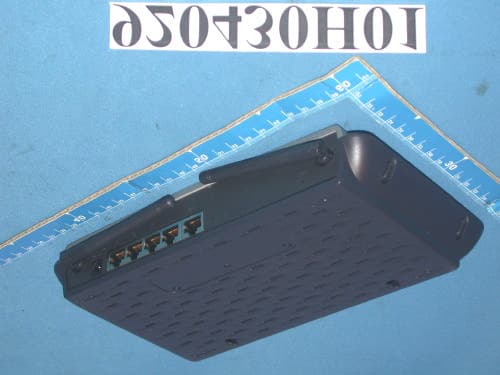
Click to zoom
Application Details
- Equipment Class
- DTS - Digital Transmission System
- Date of Grant
- Jun 04, 2003
- Application Purpose
- Original Equipment
- Date of Application
- Jun 04, 2003
- Equipment Note
- Wireless Cable/DSL Gateway Router
- Frequency Range
- 2412.00000000 - 2462.00000000
- Company
- Belkin International, Inc.
- Country
- United States
Documents & Files
Document Text
Text extracted from the exhibit documents filed with the FCC. Open a document above to read the original.
Users Manual
User Manual F5D6231-4 Wireless Cable/DSLGateway Router Share your broadband Internetconnection without cables TABLE OF CONTENTS Introduction . . . . . . . . . . . . . . . . . . . . . . . . . . . . . . . . . . . . . . . . . 1 Key Features . . . . . . . . . . . . . . . . . . . . . . . . . . . . . . . . . . . . . . . 1Package Contents . . . . . . . . . . . . . . . . . . . . . . . . . . . . . . . . . . . . 3System Requirements . . . . . . . . . . . . . . . . . . . . . . . . . . . . . . . . . 3Easy Install Wizard Software System Requirements . . . . . . . . . . . . . 3 Knowing your Belkin Router . . . . . . . . . . . . . . . . . . . . . . . . . . . . . . . 4Placement of your Wireless Router . . . . . . . . . . . . . . . . . . . . . . . . . . 8Connecting and Configuring your Cable/DSL Router . . . . . . . . . . . . . . . 9Alternate Setup Method . . . . . . . . . . . . . . . . . . . . . . . . . . . . . . . . . 20Using the Web-Based Advanced User Interface . . . . . . . . . . . . . . . . . 34Manually Configuring Network Settings . . . . . . . . . . . . . . . . . . . . . . 69Recommended Web Browser Settings . . . . . . . . . . . . . . . . . . . . . . . . 74Troubleshooting . . . . . . . . . . . . . . . . . . . . . . . . . . . . . . . . . . . . . . 76Information . . . . . . . . . . . . . . . . . . . . . . . . . . . . . . . . . . . . . . . . . 78 1 INTRODUCTION Thank you for purchasing the Belkin Wireless Cable/DSL Gateway Router (theRouter). In minutes you will be able to share your Internet connection andnetwork your computers. The following is a list of features that make your newRouter an ideal solution for your home or small office network.Key FeaturesEasy Install WizardThe Easy Install Wizard takes the guesswork out of setting up your Router.This automatic software determines your network settings for you and sets upthe Router for connection to your Internet Service Provider (ISP). In a matterof minutes, your Router will be up and running on the Internet.NOTE: Easy Install Wizard software is compatible with Windows 98, Me, 2000, and XP. If you are using another operating system, the Router can be set upusing the Alternative Method described in this manual. Integrated Wireless ConnectivityThe Router has an integrated 802.11b Wi-Fi Access Point that allows you toconnect wireless-equipped computers to the network without wires.Works with Both PCs and Mac® ComputersThe Router supports a variety of networking environments including Mac ® OS 8.x, 9.x, X v10.x, AppleTalk ® , Linux ® , Windows ® 95, 98, Me, NT ® , 2000, and XP, and others. All that is needed is an Internet browser and anetwork adapter that supports TCP/IP (the standard language of the Internet). Front-Panel Connected LED DisplayLighted LEDs on the front of the Router indicate which functions are inoperation. You ’ ll know at-a-glance whether your Router is connected to the Internet. This feature eliminates the need for advanced software and status-monitoring procedures. Vertical or Horizontal Desktop ApplicationYour Router can stand vertically on the desktop to save space, or lay downflat on a shelf or under your modem. The included vertical mounting base letsyou decide how to position the Router.Web-Based Advanced User InterfaceYou can set up the Router ’ s advanced functions easily through your web browser, without having to install additional software onto the computer.There are no disks to install or keep track of and, best of all, you can makechanges and perform setup functions from any computer on the networkquickly and easily. INTRODUCTION 2 NAT IP Address SharingYour Router employs Network Addr ess Translation (NAT) to share the single IP address assigned to you by your Internet Service Provider while saving thecost of adding additional IP addresses to your Internet service account.SPI Fi rewall Your Router is equipped with a firewall that will protect your network from awide array of common hacker attacks including IP Spoofing, Land Attack, Pingof Death (PoD), Denial of Service (DoS), IP with zero length, Smurf Attack,TCP Null Scan, SYN flood, UDP flooding, Tear Drop Attack, ICMP defect, RIPdefect, and fragment flooding.Integrated 10/100 4-Port SwitchThe Router has a built-in, 4-port network switch to allow your wiredcomputers to share printers, data and MP3 files, digital photos, and muchmore. The switch features automatic detection so it will adjust to the speedof connected devices. The switch will transfer data between computers andthe Internet simultaneously without interrupting or consuming resources.Universal Plug-and-Play (UPnP) CompatibilityUPnP (Universal Plug-and-Play) is a technology that offers seamless operationof voice messaging, video messaging, games, and other applications that areUPnP-compliant.Support for VPN Pass-ThroughIf you connect to your office network from home using a VPN connection,your Router will allow your VPN-equipped computer to pass through theRouter and to your office network.Built-In Dynamic Host Configuration Protocol (DHCP) on-board makes for the easiest possible connection of a network. The DHCP server will assign IPaddresses to each computer automatically so there is no need for acomplicated networking setup. MAC Address FilteringFor added security, you can set up a list of MAC addresses (unique clientidentifiers) that are allowed access to your network. Every computer has itsown MAC address. Simply enter these MAC addresses into a list using the web-based user interface and you can control access to your network.Applications and Advantages• Economically connect multiple computers to a single Internet connection • SOHO (Small Office/Home Office) networking needs Provides the easy and quick small network installation SOHO users need. INTRODUCTION 3 Package Contents • Belkin Wireless Cable/DSL Gateway Router • Vertical Mounting Base (optional use) • Category 5 Networking Cable • Power Supply • Belkin Easy Install Wizard Software CD • User Manual System Requirements • Broadband Internet co…
Text truncated - open the document above for the full version.
Users Manual
USING THE WEB-BASED ADVANCED USER INTERFACE 41 Using the Accept “ ANY ” SSID Feature Note: This advanced feature should be employed by advanced users only. A feature of wireless networking is the ability to scan for networks and connect to themeasily. For instance, you can set up a wireless-equipped computer to connect toand an SSID called “ ANY ” . This forces the wireless network adapter in the computer to look for any network in the area and connect to it. For ease-of-use this is veryconvenient, but in some cases you may want users to have to specify the name ofthe network. You can program the Router to reject a wireless-equipped computerlooking for an SSID of “ ANY ” . Remove the check mark in the box next to “ Accept ‘ ANY ’ SSID ” , then click “ Apply Changes ” . The change is immediate. Each computer now needs to be set to connect to your specific SSID; an SSID of “ ANY ” will no longer be accepted. Refer to the documentation of your wireless network adapterfor information on making this change. Using the Broadcast SSID FeatureNote: This advanced feature should be employed by advanced users only. For security, you can choose not to broadcast your network ’ s SSID. Doing so will keep your network name h idden from computers that are scanning for the presence of wireless networks. To turn off the broadcast of the SSID, remove the check markfrom the box next to “ Broadcast SSID ” , then click “ Apply Changes ” . The change is immediate. Each computer now needs to be set to connect to your specific SSID;an SSID of “ ANY ” will no longer be accepted. Refer to the documentation of your wireless network adapter for information on making this change. Changing the Wireless Encryption SettingsClicking on the “ Encryption ” link in the “ Wireless ” tab will take you to the Encryption settings screen. To make setting up your network for the first time easy,the Router ships with encryption turned off. If you wish to turn on encryption, youcan do so from this page. Turning on encryption will require you to set each ofyour wireless-equipped computers with the same encryption settings that youmake in the Router. Refer to the documentation of your wireless network adapterfor information on making this change.There are two types of encryption to choose from: 64-bit and 128-bit encryption.Using encryption will make your network more secure, but will slow down thenetwork performance. Although network performance will be reduced, it is likelythe change will not be detectable to users of the network. USING THE WEB-BASED ADVANCED USER INTERFACE 42 Setting Encryption Automatically Using a PassphraseNote to Mac users: The Passphrase option will not operate with Apple® AirPort®. Toconfigure encryption for your Mac computer, set the encryption using the manualmethod described in the next section.1. Select “ 64-bit automatically ” or “ 128-bit automatically ” from the drop-down menu. 2. Type in a passphrase. A passphrase is like a password. It can be a mixtureof numbers and letters. After you type in your passphrase, click“ Generate ” . When you click “ Generate ” , the key fields below will become populated. Note: 64-bit encryptionwill generate fourkeys and 128-bitencryption willgenerate only onekey. Select the key you want touse by clickingthe radio buttonnext to it. Click“ Apply Changes ” . 3. Encryption in the Router is now set. Each of your computers on yourwireless network will now need to be configured with the samepassphrase. Refer to the documentation of your wireless network adapterfor information on making this change. USING THE WEB-BASED ADVANCED USER INTERFACE 43 Setting Encryption Manually Using a Hexadecimal KeyA hexadecimal key is a mixture of numbers and letters from A – F and 0 – 9. 64-bit keys are five 2-digit numbers. 128-bit keys are 13 2-digit numbers.For instance:AF 0F 4B C3 D4 = 64-bit keyC3 03 0F AF 0F 4B B2 C3 D4 4B C3 D4 E7 = 128-bit keyIn the boxes below, make up your key by writing in two characters between A – F and 0 – 9. You will use this key to program the encryption settings on your Router and your wireless computers. Note to Mac users: Original Apple AirPort products support 64-bit encryption only.Apple AirPort 2 products can support 64-bit or 128-bit encryption. Please checkyour product to see which version you are using. If you cannot configure yournetwork with 128-bit encryption, try 64-bit encryption.1. Select “ 64-bit manually ” or “ 128-bit manually ” from the drop-down menu. 2. If using 64-bitencryption, there willbe four key fields. Ifusing 128-bitencryption, there willbe one key field. Inthe key field(s), type in the hexadecimal key(s) that you wish to use.When finished typing in your keys, select which key you want to use byclicking the radio button next to it. Click “ Apply Changes ” . 3. Encryption in the Router is now set. Each of your computers on yourwireless network will now need to be configured with the samehexadecimal key. Refer to the documentation of your wireless networkadapter for information on making this change. USING THE WEB-BASED ADVANCED USER INTERFACE 44 Using the Access Point ModeNote: This advanced feature should be employed by advanced users only. The Router can be configured to work as a wireless network access point. Using thismode will defeat the NAT IP sharing feature and DHCP server. In AP mode, theRouter will need to be configured with an IP address that is in the same subnetas the rest of the network that you will br idge to. The default IP address is 192.168.2.254 and subnet mask is 255.255.255.0. These can be customized foryour need. 1. Enable the AP mode my selecting “ Enable ” in the “ Use as Access Point only ” page. When you select this option, you will be able to change the IPsettings. 2. Set your IP settings to match your network. Click “ Apply Changes ” . 3. Connect a cable from the WAN port on the Router to your existing network. The Router is now acting as an Access Point. To access the Router advanceduser interface again, …
Text truncated - open the document above for the full version.
Cover Letter(s)
Belkin Corporation FCC ID: K7SFSD623142 Federal Communications Commission Authorization and Evaluation Division Confidentiality Request Pursuant to Sections 0.457 and 0.459 of the Commission's Rules, the Applicant hereby requests confidential treatment of infonnation accompanying this Application as outlined below: Schematics Block Diagram The above materials contain trade secrets and proprietary information not customarily released to the public. The public disclosure of these matters might be harmful to the Applicant and provide unjustified benefits to its competitors. The Applicant understands that pursuant to Rule 0.457, disclosure of this Application and all accompanying documentation will not be made before the date of the Grant for this application. Sincerely yours, ~t' ~~-:;:::","""" Signature Printed Name: Mr. Gene A. Byrd Title: Configuration Manager Belkin Corporation Date: 11/19/2002 Corporate Offices. 501 West Walnut Street. Compton, CA .90220-5221 .T: 310.898.1100 .F: 310.898.1111 .belkin.com
Cover Letter(s)
Belkin Corporation 501 West Walnut Street, Compton, CA 90220 Tel: 310-604-2448 Fax: 310-631-3629 www.belkin.com For the following equipment: Product Name: Wireless Cabie/DSL Gatewav Router Model No.: F5D6231-4 Trade Name: Belkin Is herewith confirmed to be in compliance with the requirements of ANSI C63.4 & FCC part 15 regulations. The test result has been shown in the Taiwan Token EMC Engineering Corp. test report with number TTEMC-F98179. And this compliance is subject to the following two conditions: This device may not cause harmful interference and, This device must accept any interference received, including interference that may cause undesired operation. The following local Manufacturer/Importer is responsible for this declaration: Belkin Corporation (Company Name) 501 West Walnut Street, Compton, CA 90220 (Company Address) TEL: 310-604-2448 FAX: 31 0-631 -3629 Mr. Gene A. Byrd / Configuration Manager (Name) ./~(Signature) / (Date)
Cover Letter(s)
Belkin Corporation May 16, 2003 To Whom It May Concern: We, the undersigned, hereby authorize as our agent: Agent: Advance Data Technology Corp. 47 14th Lin,Chiapao Tsuen Linko, Taipei Taiwan, R.O.C. To act on our behalf in all matters relating to FCC approval for equipment authorization, including signing of all documents relating to authorization of the part(s) listed below. Any and all acts carried out by Advance Data Technology Corp. to obtain such authorization on our behalf shall have the same effects as acts of our own, provided that Advance Data Technology shall not have the authority to bind Belkin Components to any contracts or to make any similar commitments. Product(s): F5D6231-4 Wireless CablelDSL Gateway Router We, the undersigned, hereby certify that we are not subject to denial of Federal benefits, including FCC benefits, pursuant to Section 5301 of the Anti-Drug Abuse Act of 1998. 21 U.S.C. 853 (a). This authorization is valid one year from the date of this letter or until written notice from the applicant. Gene A. Byrd Configuration Manager Belkin Corporation Coroorate Offices. 501 West Walnut Street. ComDton. CA .90220-5221 .T: 310.898.1100 .F: 310.898.1111 .belkin.com
External Photos
Page 1 CONSTRUCTION PHOTOS OF EUT Page 2
ID Label/Location Info
(Fig. 1) FCC ID: K7SF5D623142 FCC LABEL LOCATION The label will be permanently affixed at a conspicuous location on the device. Label
ID Label/Location Info
92 05 12 MM Backgroud: As Base(Black Gray) Word: As Cover(Gray) 50# 0.2mm Sylin Scale:1:1 UL Label Matelized+DPP UL Approved R01 146000030900E WG3005D-AK 1. Decied by import and export country for example: -MADE IN TAIWAN Decied by Vendor ID number NOTE: 1.Printing lnk and material must base on WEEE environment protect standard 2.Printing position tolerance : +/-0.3mm R8.8*4 96.8 2 6 . 9
Operational Description
FCC ID: K7SF5D623142 Report No.: 920430H01 ADT No.: 920430H01 Operational Description The transmitter of the EUT (Wireless Cable/DSL Gateway Router) is powered by power adapter. The antenna used in this product is Dipole Antenna without connector. Under normal use condition, the user has to keep at least 20cm separation distance between radiator and the body of the user. The other instruction, please have a look at the users manual. DSSS Information This device is Direct Sequence Spread Spectrum, the data is mixed by pseudorandom code which is an orthogonal code. The mixed data is digital modulated by DBPSK and DQPSK technique depends on the data rates. The CCK coding is applied for increasing the data rate, and also the processing gain will be increased. The bit rates are 1,2,5.5,11Mbps.
RF Exposure Info
FCC ID: K7SF5D623142 Report No.: 920430H01 RF EXPOSURE REPORT REPORT NO.: RF920430H01 MODEL NO.: F5D6231-4 ACCORDING: FCC Guidelines for Human Exposure IEEE C95.1 APPLICANT: Belkin Corporation ADDRESS: 501, West Walnut Street, Compton CA 90220-5221 USA ISSUED BY: Advance Data Technology Corporation LAB LOCATION: No. 81-1, Lu Liao Keng, 9 Ling, Wu Lung Tsuen, Chiung Lin Hsiang, Hsin Chu Hsien, Taiwan, R.O.C. Lab Code: 200376-0 FCC ID: K7SF5D623142 Report No.: 920430H01 RF Exposure Measurement 1. Introduction In this document, we try to prove the safety of radiation harmfulness to the human body for our product. The limit for Maximum Permissible Exposure (MPE) specified in FCC 1.1310 is followed. The Gain of the antenna used in this product is measured in a Fully Anechoic Chamber (FAC) calibrated for antenna measurement in ADT, and also the maximum total power input to the antenna is measured. Through the Friis transmission formula and the maximum gain of the antenna, we can calculate the distance, away from the product, where the limit of MPE is reached. Although the Friis transmission formula is a far field assumption, the calculated result of that is an over-prediction for near field power density. We will take that as the worst case to specify the safety range. 2. RF Exposure Limit According to FCC 1.1310: The criteria listed in the following table shall be used to evaluate the environmental impact of human exposure to radio-frequency (RF) radiation as specified in 1.1307(b) LIMITS FOR MAXIMUM PERMISSIBLE EXPOSURE (MPE) Frequency Range (MHz) Electric Field Strength (V/m) Magnetic Field Strength (A/m) Power Density (mW/cm 2 ) Average Time (minutes) (A)Limits For Occupational / Control Exposures 300-1500 ... ... F/300 6 1500-100,000 ... ... 5 6 (B)Limits For General Population / Uncontrolled Exposure 300-1500 ... ... F/1500 6 1500-100,000 ... ... 1.0 30 F = Frequency in MHz FCC ID: K7SF5D623142 Report No.: 920430H01 3. Friis Formula Friis transmission formula : Pd = (Pout*G) / (4*pi*r 2 ) where Pd = power density in mW/cm 2 Pout = output power to antenna in mW G = gain of antenna in linear scale Pi = 3.1416 R = distance between observation point and center of the radiator in cm Pd is the limit of MPE, 1 mW/cm 2 . If we know the maximum Gain of the antenna and the total power input to the antenna, through the calculation, we will know the MPE value at distance 20cm. Ref. : David K. Cheng, Field and Wave Electromagnetics, Second Edition, Page 640, Eq. (11-133). 4 EUT Operating condition The software provided by Manufacturer enabled the EUT to transmit and receive data at lowest, middle and highest channel individually. 5 Climate Condition The temperature and related humidity: 20 deg. C and 63 % RH 6. Classification This device is not fixed inside the host equipment, it is connected with host through wire. So it is easy to be re-located in the place where at least 20 cm far away from the body of the user. Warning statement to the user for keeping at least 20cm or more separation distance with the antenna should be included in users manual. So, this device is classified as Mobile Device. FCC ID: K7SF5D623142 Report No.: 920430H01 7 Test Results 7.1 Antenna Gain The maximum Gain measured in Fully Anechoic Chamber are 1.8dBi or 1.51 (numeric). 7.2 Output Power Into Antenna & RF Exposure value at distance 20cm: Channel Channel Frequency (MHz) Output Power to Antenna (mW) Power Density (mW/cm 2 ) Limit of Power Density (mW/cm 2 ) 1 2412 53.088 0.016 1.0 6 2437 62.374 0.0188 1.0 11 2462 51.88 0.0156 1.0
Test Report
FCC ID: K7SF5D623142 Report No.: RF920430H01 1 Issued: May 23, 2003 ADT No. 920430H01 FCC TEST REPORT REPORT NO.: RF920430H01 MODEL NO.: F5D6231-4 RECEIVED: Apr. 30, 2003 TESTED: Apr. 30 to May 07, 2003 APPLICANT: Belkin Corporation ADDRESS: 501, West Walnut Street, Compton CA 90220-5221 USA ISSUED BY: Advance Data Technology Corporation LAB LOCATION: No. 81-1, Lu Liao Keng, 9 Ling, Wu Lung Tsuen, Chiung Lin Hsiang, Hsin Chu Hsien, Taiwan, R.O.C. This test report consists of 50 pages in total. It may be duplicated completely for legal use with the approval of the applicant. It should not be reproduced except in full, without the written approval of our laboratory. The client should not use it to claim product endorsement by CNLA, NVLAP or any government agencies. The test results in the report only apply to the tested sample. Lab Code: 200376-0 FCC ID: K7SF5D623142 Report No.: RF920430H01 2 Issued: May 23, 2003 ADT No. 920430H01 Table of Contents 1 CERTIFICATION......................................................................................................4 2 SUMMARY OF TEST RESULTS..........................................................................5 3 GENERAL INFORMATION....................................................................................6 3.1 GENERAL DESCRIPTION OF EUT.....................................................................6 3.2 DESCRIPTION OF TEST MODES.......................................................................7 3.3 GENERAL DESCRIPTION OF APPLIED STANDARDS..................................7 3.4 DESCRIPTION OF SUPPORT UNITS................................................................8 2.1 CONFIGURATION OF SYSTEM UNDER TEST...............................................9 4 TEST TYPES AND RESULTS.............................................................................10 4.1 CONDUCTED EMISSION MEASUREMENT...................................................10 4.1.1 TEST INSTRUMENTS.............................................................................................10 4.1.2 TEST PROCEDURES...............................................................................................11 4.1.3 DEVIATION FROM TEST STANDARD....................................................................11 4.1.4 TEST SETUP...........................................................................................................12 4.1.5 EUT OPERATING CONDITIONS............................................................................13 4.1.6 TEST RESULTS.......................................................................................................14 4.2 RADIATED EMISSION MEASUREMENT.........................................................20 4.2.1 LIMITS OF RADIATED EMISSION MEASUREMENT............................................20 4.2.2 TEST INSTRUMENTS.............................................................................................21 4.2.3 TEST PROCEDURES..............................................................................................22 4.2.4 DEVIATION FROM TEST STANDARD...................................................................22 4.2.5 TEST SETUP...........................................................................................................23 4.2.6 EUT OPERATING CONDITIONS............................................................................23 4.2.7 TEST RESULTS.......................................................................................................24 4.3 6dB BANDWIDTH MEASUREMENT.................................................................28 4.3.1 LIMITS OF 6dB BANDWIDTH MEASUREMENT....................................................28 4.3.2 TEST INSTRUMENTS.............................................................................................28 4.3.3 TEST PROCEDURE................................................................................................29 4.3.4 DEVIATION FROM TEST STANDARD...................................................................29 4.3.5 TEST SETUP...........................................................................................................29 4.3.6 EUT OPERATING CONDITIONS............................................................................29 4.3.7 TEST RESULTS.......................................................................................................30 4.4 MAXIMUM PEAK OUTPUT POWER.................................................................34 4.4.1 LIMITS OF MAXIMUM PEAK OUTPUT POWER MEASUREMENT......................34 4.4.2 INSTRUMENTS.......................................................................................................34 4.4.3 TEST PROCEDURES..............................................................................................35 4.4.4 DEVIATION FROM TEST STANDARD...................................................................35 FCC ID: K7SF5D623142 Report No.: RF920430H01 3 Issued: May 23, 2003 ADT No. 920430H01 4.4.5 TEST SETUP...........................................................................................................35 4.4.6 EUT OPERATING CONDITIONS............................................................................35 4.4.7 TEST RESULTS.......................................................................................................36 4.4.8 LIMITS OF POWER SPECTRAL DENSITY MEASUREMENT..............................37 4.4.9 TEST INSTRUMENTS.............................................................................................37 4.4.10 TEST PROCEDURE................................................................................................38 4.4.11 DEVIATION FROM TEST STANDARD...................................................................38 4.4.12 TEST SETUP...........................................................................................................38 4.4.13 EUT OPERATING CONDITION..........................…
Text truncated - open the document above for the full version.
Test Setup Photos
FCC ID: K7SF5D623142 Report No.: RF920430H01 48 Issued: May 23, 2003 ADT No. 920430H01 5 PHOTOGRAPHS OF THE TEST CONFIGURATION CONDUCTED EMISSION TEST FCC ID: K7SF5D623142 Report No.: RF920430H01 49 Issued: May 23, 2003 ADT No. 920430H01 RADIATED EMISSION TEST
Contact Information
Applicant
Jay TU(Manager, Regulatory Compliance)
Technical Contact
Advance Data Technology CorporationEric Lin
[email protected]+886 3 593 5343
81-1 Luliaoken, 9th Lin · Hsinchu · Taiwan
Test Firm
Bureau Veritas CPS (H.K.) Ltd. Taoyuan BranchRichard Chen
Technical Specifications
| # | Rule Parts | Frequency Range | Power Output |
|---|---|---|---|
| 1 | 15C | 2.41 GHz - 2.46 GHz | 63.00 mW |
Other Applications from Belkin International, Inc.
K7S-CAB029
Aug 11, 2026SureFind Loop Cable Tag
Equipment Class
DTS - Digital Transmission SystemK7SBPD024
Aug 10, 2026UltraCharge Pro Slim Magnetic Power Bank 5K with BoostSolid Cell
Equipment Class
DCD - Part 15 Low Power Transmitter Below 1705 kHzK7SMMA016
Jul 22, 2026SureFind Wallet Stand
Equipment Class
DTS - Digital Transmission SystemK7SMMA015
Jul 10, 2026SureFind
Equipment Class
DTS - Digital Transmission SystemK7SAUC018
Jun 17, 2026SoundForm Dot ANC Earbuds, SoundForm Dot Earbuds
Equipment Class
DTS - Digital Transmission System