K7SF5D7001AWireless PCI Adapter
Belkin International, Inc.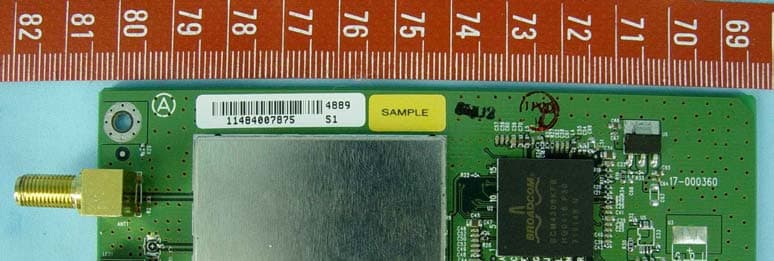
Click to zoom
Application Details
- Equipment Class
- DTS - Digital Transmission System
- Date of Grant
- Nov 11, 2004
- Application Purpose
- Original Equipment
- Date of Application
- Nov 11, 2004
- Equipment Note
- Wireless PCI Adapter
- Frequency Range
- 2412.00000000 - 2462.00000000
- Company
- Belkin International, Inc.
- Country
- United States
Documents & Files
Document Text
Text extracted from the exhibit documents filed with the FCC. Open a document above to read the original.
Users Manual
F5D7001 Connect your desktop computer to a FASTER wireless network User Manual High-Speed Mode Wireless G Desktop Network Card 11 1 Introduction. . . . . . . . . . . . . . . . . . . . . . . . . . . . . . . . . . . . . . . . . . . . 1 Benefits of a Home Network. . . . . . . . . . . . . . . . . . . . . . . . . . . . . . 1 Advantages of a Wireless Network. . . . . . . . . . . . . . . . . . . . . . . . . 1 Placement of your Wireless Networking Hardware for Optimal Performance . . . . . . . . . . . . . . . . . . . . . . . . 2 2 Overview . . . . . . . . . . . . . . . . . . . . . . . . . . . . . . . . . . . . . . . . . . . . . . 6 Product Features . . . . . . . . . . . . . . . . . . . . . . . . . . . . . . . . . . . . . . 6 Applications and Advantages . . . . . . . . . . . . . . . . . . . . . . . . . . . . 7 Product Specifications . . . . . . . . . . . . . . . . . . . . . . . . . . . . . . . . . . 8 System Requirements . . . . . . . . . . . . . . . . . . . . . . . . . . . . . . . . . . 9 Package Contents . . . . . . . . . . . . . . . . . . . . . . . . . . . . . . . . . . . . . 9 3 Installing and Setting Up the Card . . . . . . . . . . . . . . . . . . . . . . . 10 Step 1: Install the Software. . . . . . . . . . . . . . . . . . . . . . . . . . . . . . 10 Step 2: Insert the Card into your Computer. . . . . . . . . . . . . . . . . 11 Step 3: Let Windows Finish the Installation . . . . . . . . . . . . . . . . . 13 4 Using the Belkin Wireless LAN Utility. . . . . . . . . . . . . . . . . . . . 16 Setting Wireless Network Preferences . . . . . . . . . . . . . . . . . . . . . 16 Securing your Wi-Fi Network . . . . . . . . . . . . . . . . . . . . . . . . . . . . 19 Monitoring the Status of your Network Connection. . . . . . . . . . . 32 Monitoring Data Transfer. . . . . . . . . . . . . . . . . . . . . . . . . . . . . . . . 34 Finding Available Networks in your Area . . . . . . . . . . . . . . . . . . . 35 Performing Diagnostic Tests on your Computer . . . . . . . . . . . . . 36 5 Troubleshooting . . . . . . . . . . . . . . . . . . . . . . . . . . . . . . . . . . . . . . . 38 6 Information . . . . . . . . . . . . . . . . . . . . . . . . . . . . . . . . . . . . . . . . . . . 47 Table of Contents 11 section 1 2 3 4 5 6 Introduction Thank you for purchasing the Belkin High-Speed Mode Wireless G Desktop Network Card (the Card). Now you can take advantage of this great new technology and gain the freedom you need around the home or office without using cables. The Card works like a conventional network card, but without the wires. The easy installation and setup will have you networking wirelessly in minutes. Please be sure to read through this User Manual completely, and pay special attention to the section entitled “Placement of your Wireless Networking Hardware for Optimal Performance”. By following our simple setup instructions your Belkin Home Network will allow you to: • Share one high-speed Internet connection with all the computers in your home • Share resources, such as files, and hard drives among all the connected computers in your home • Share a single printer with the entire family • Share documents, music, video, and digital pictures • Store, retrieve, and copy files from one computer to another • Simultaneously play games online, check Internet e-mail, and chat Here are some of the advantages of setting up a Belkin Wireless Network: • Mobility –you’ll no longer need a dedicated “computer room”— now you can work on a networked laptop or desktop computer anywhere within your wireless range • Easy installation – Belkin Easy Installation Wizards make setup simple • Flexibility – set up and access printers, computers, and other networking devices from anywhere in your home • Easy Expansion – the wide range of Belkin networking products let you expand your network to include devices such as printers and gaming consoles • No cabling required – you can spare the expense and hassle of retrofitting Ethernet cabling throughout the home or office • Widespread industry acceptance – choose from a wide range of interoperable networking products 32 Introduction 32 Introduction Placement of your Wireless Networking Hardware for Optimal Performance Your wireless connection will be stronger the closer your computer is to your Wireless Router (or Access Point). Typical indoor operating range for your wireless devices is between 100 and 200 feet. In the same way, your wireless connection and performance will degrade somewhat as the distance between your Wireless Router (or Access Point) increases. This may or may not be noticeable to you. As you move further from your Wireless Router (or Access Point), connection speed may decrease. Factors that can weaken signals simply by getting in the way of your network’s radio waves are metal appliances or obstructions, and walls. If you have concerns about your network’s performance that might be related to range or obstruction factors, try moving the computer to a position between five and ten feet from the Wireless Router (or Access Point), in order to see if distance is the problem. If difficulties persist even at close range, please contact Belkin Technical Support. Placement of your Wireless Networking Hardware Note: While some of the items listed below can affect network performance, they will not prohibit your wireless network from functioning; if you are concerned that your network is not operating at its maximum effectiveness, this checklist may help. 1. Placement of your Wireless Router or Access Point Place your Wireless Router (or Access Point), the central connection point of your network, as close as possible to the center of your wireless network devices. To achieve the best wireless network coverage for your “wireless clients,” (i.e. computers enabled by Belkin Wireless Notebook Network Cards, Wireless Desktop Network Cards, and Wireless USB Adapters): • Ensure that your Wireless Router (or Access Point) antennas are parallel to each other, and are positioned …
Text truncated - open the document above for the full version.
Users Manual
1111 section 1.4 The installer will now start. Click “Next” and follow the on-screen instructions. 1.5 After the installation is complete, click “Finish” to shut down your computer. Step 2 Inse rt the Card into the Computer WARNING: Be sure to power off your computer and disconnect your power cord before opening up your computer. 2.1 Remove the screws behind your computer case that secure the computer cover and remove cover. 2.2 Touch any metal part of the case to discharge static electricity, to avoid damage your product or your computer. 2.3 Locate an empty PCI expansion slot. It is usually white in color. Installing and Setting Up the Card 1 2 3 4 5 6 13121312 2.4 Confirm that the Card will fit into the slot you have chosen. Keep in mind that the included antenna needs to be oriented with the top pointing up. If there are cables and other connectors in the way, try to pick the PCI slot that has the fewest obstructions to the correct positioning of the antenna. 2.5 Remove the metal port cover from the back of the computer that corresponds to the PCI slot you selected. If there is a screw, place it in a safe place, as you will be using it to attach the Card to the computer later. 2.6 Push the Card firmly into the PCI slot that you have chosen. Apply pressure as needed until the connector is fully seated. 2.7 Now secure the Card with the screw that you previously placed in a safe place. 2.8 Carefully screw the antenna onto the threaded connector on the Card. Turn the antenna until it is vertical and pointing up. 2.9 Replace the computer’s cover. Now that the Card is installed, you can reconnect the power cord, and turn it back on. Installing and Setting Up the Card 1313 section Step 3 Let Windows Finish the Installation 3.1 After powering on your computer, you will see a “Found New Hardware Wizard” screen. Select “Install the software automatically (Recommended)” and click “Next”. Note: Specific screens differ depending upon which version of the Windows OS you are using. 3.2 Depending on the version of Windows you are using, you might also see a screen similar to this one. This DOES NOT mean there is a problem as the drivers have been fully tested and are compatible with this Windows operating system. Select “Continue Anyway” and follow the on-screen instructions. Installing and Setting Up the Card 1 2 3 4 5 6 15141514 3.3 Windows will ask you where the drivers are located. Make no changes and click “Next” until you see the screen that asks you to click “Finish” to complete the installation. Note: Specific screens differ depending upon which version of the Windows OS you are using. 3.4 When the installation is complete, a small Signal Indicator icon (red) in your system tray (bottom right corner of most screens) will appear. Double-click the Signal Indicator icon to bring up the “Wireless Network” screen. 3.5 Select the network you want to connect to under “Available networks” and click “Connect”. Installing and Setting Up the Card 1515 section 3.6 The Signal Indicator icon in your system tray should now turn green (yellow if the signal is weak.) Installation is now complete! Double-click the Signal Indicator icon to bring up the “Wireless Network” screen. The following screen will appear: Next, clicking on the “Advanced” button will allow you to view and configure more options of your Card. The “Advanced” button will take you to the Belkin Wireless LAN Utility. Installing and Setting Up the Card 1 2 3 4 5 6 17161716 Setting Wireless Network Preferences Click on the “Wireless Networks” tab. (a) Enable Radio Use this option to turn your wireless network radio ON or OFF. You may want to turn the radio off while in airplanes or to conserve the battery life of your mobile computer. When the radio is disabled, the power LED on your Card will turn off and the Windows 2000 or XP system tray wireless network icon will be depicted with an “X”. (b) Available Networks This displays a list of wireless networks in your area. If you don’t see a name in the box, click on the “Refresh” (j) button to rescan for any available networks. To connect to a network, select a network name in the Available Networks list box and click the “Configure” (i) button. Click “OK” (m) in the “Wireless Network Properties” box to add the network name to the “Preferred Networks” (c) list. Wait up to one minute for the network connection to be made. Your computer is connected to the selected network when you see a blue bubble (d) on top of the icon for that network. (a) (b) (c) (d) (e) (f) (g) (h) (l) (j) (i) (k) Using the Belkin Wireless LAN Utility 1717 section (c) Preferred Networks Displays a list of the networks that you have previously configured. The one with the blue bubble (d) is the network you are currently connected to. You may rank the networks by selecting the network name in the “Preferred Networks” list then clicking on the “Move Up” and “Move Down” (k) buttons. Networks appearing higher on the list will be preferred over networks listed lower on the list. If a preferred network is unavailable, the Card will attempt to connect to the next available network on the list. (e, f) Add, Remove You may “Add” (e) and “Remove” (f) networks from the Preferred Networks list by using these buttons. (g) System Tray Icon Check this box so that the wireless icon appears on your system tray. (h) Properties To change the properties and WEP (security) settings of a network, select a network from the Preferred Networks (c) then click on the “Properties” (h) button. (l) Advanced Allows you to select the type of network you want to connect to. When the “Advanced” (l) button is checked, the screen on the next page will appear. Using the Belkin Wireless LAN Utility 1 2 3 4 5 6 19181918 Any Available Network (Access Point Preferred) When this option is selected, the Card will attempt to connect to any available network in the area. Wireless router or access point networks will be preferred networks over Ad-Hoc networks. Access Point …
Text truncated - open the document above for the full version.
Users Manual
3333 1 2 3 4 5 6 section Using the Belkin Wireless LAN Utility (f) Client IP Address Shows the IP address of the computer. The IP address is obtained automatically by default. You may set the IP address manually through Windows Networking Properties. (g) Network Connection Type Shows the current wireless mode the Card is operating in. There are two operating modes: Infrastructure and Ad-Hoc. Infrastructure is the most common mode to operate in. Infrastructure mode is used when connecting your PC to a wireless router or a wireless access point. Ad-Hoc mode is used to connect two or more computers together without the use of a wireless router or an access point. (h) Radio State Shows whether the radio of your wireless client is enabled or disabled. (i) Signal Displays the wireless signal strength in decibels (dBm). The decibel scale is negative, so smaller absolute values correspond to stronger signals (i.e. -20 dBm is stronger than -80 dBm). The signal to noise ratio (SNR) is the difference between the signal and the noise (e.g. if the noise is -80 dBm and the signal is -20 dBm, the SNR is 60 dB); the larger the SNR, the better. In general, connections should have an SNR greater than 20 dBm, or the user may experience poor reliability and/or performance. If the signal is less than -50 dBm, the user should consider repositioning their workstation or Access Point, rotating the Access Point’s antennas, or Limiting their Transmission Rate (described on page _ of the troubleshooting section of the manual), to ensure a reliable wireless connection. (j) Noise Displays the intensity of the external noise, on this wireless channel, in decibels (dBm). If the noise is greater than -70 dBm, the user should consider changing the wireless channel used, in their Access Point, to ensure a reliable wireless connection. 35343534 Using the Belkin Wireless LAN Utility Monitoring Data Transfer Click on the “Statistics” tab. The Statistics tab shows you how much data has been sent and received and if any errors occurred. This screen is mostly for diagnostics. Note that the number of data packets lost is recorded. A large number of lost data packets may indicate that there is a problem or interference in your area. (See the Troubleshooting section for tips on how to improve performance.) 3535 1 2 3 4 5 6 section Using the Belkin Wireless LAN Utility Finding Available Networks in your Area Click on the “Site Monitor” tab. Clicking on the “Site Monitor” tab will display a list of all available wireless routers or access points in your area. (a) Network Name (SSID) The network name of the wireless router or access point. (b) Channel The current operating channel of the wireless router or access point. (c) Signal Strength The signal strength of the related wireless router or access point. (d) WEP (Encryption) Will display “Off” when encryption is disabled, “64-bit” when 64-bit encryption is enabled, and “128-bit” when 128-bit encryption is enabled. (e) Ad-Hoc Networks Only Check this box to display available Ad-Hoc networks only. An Ad-Hoc network is a computer-to-computer network. (f) Advanced Displays additional information about the selected network. (g) Freeze Takes a “snapshot” of the signal strength at the time of the site survey. Click again to unfreeze. (a) (b) (c) (d) (e) (f) (g) 37363736 Performing Diagnostic Tests on your Connection Click on the “Diagnostics” tab. This page allows you to perform several diagnostic tests that are available for your Belkin Wireless G Desktop Network Card. Control Registers This test verifies the read and write capabilities of the network controller registers by writing various values to the registers and verifying the result. The device driver uses these registers to perform network functions such as sending and receiving information. If the test fails, the network adapter may not work properly. SPROM Format Version This test verifies the content of the SPROM by reading a portion of the SPROM and computing the checksum. The test fails if the computed checksum is different than the checksum stored in the SPROM. Memory Tests This tests verifies that the network controller internal memory is functioning properly. The test writes patterned values to the memory and reading back the results. The test fails if an erroneous value is read back. The network controller will not function without its internal memory. Using the Belkin Wireless LAN Utility 3737 1 2 3 4 5 6 section Using the Belkin Wireless LAN Utility Interrupt Test This test verifies that the NDIS driver is able to receive interrupts from the network controller. Loopback Test This test verifies that the NDIS driver is able to send packets and receive packets from the network controller. LED Test This test verifies that your 802.11g wireless networking hardware is functioning correctly. 3938 Troubleshooting 3938 Troubleshooting I can’t connect to the Internet wirelessly If yo u are unable to connect to the Internet from a wireless computer, please check the following items: 1. Look at the lights on your Wireless Router. If you’re using a Belkin Wireless Router, the lights should be as follows: • The “Power” light should be on. • The “Connected” light should be on, and not blinking. • The “WAN” light should be either on or blinking. If your Belkin Wireless Router’s lights have the above characteristics, go to number 2. below. If this is NOT the case, make sure: • The Router power cord is plugged in • All cables are connected between the router and the modem • All the modem’s LEDs are functioning correctly. If not, see your modem’s user manual. • Reboot the User Manual • Reboot the Modem If you continue to have issues, please contact Belkin Technical Support. If you are not using a Belkin Wireless Router, consult that router manufacturers user guide. 2. Open your wireless utility software by clicking on the icon in the system tray at the bottom right-hand corner of the screen. If you’re using a Belkin wireless card, the tr…
Text truncated - open the document above for the full version.
Cover Letter(s)
belkin.com 501, West Walnut Street, Compton. USA 90220-5221 TEL: 310-604-2448 FAX: 310-631-3629 POWER OF ATTORNEY To whom it may concern We, the undersigned Belkin CorfJoration hereby authorize Advance Data Technology Corporation (ADT) of Taiwan to act on our behalf in all matters relating to all processes required in the FCC Part 15C approval and any communication needed with the national authority. Any and all acts carried out by ADT on our behalf shall have the same effects as acts of our own. If you have any questions regarding the authorization, please don't hesitate to contact us. Thank you! Sincerely yours, t)"1'\~-<~\" l J ~ L Michael Maher Engineering Services Manager TEL: 310-604-2478 FAX: 310-631-3629 e-mail: [email protected]
Cover Letter(s)
belkin.com 501. West Walnut Street.. Compton. USA 90220-5221 TEL: 310-604-2448 FAX; 310-631-3629 Federal Communications Commission Authorization and Evaluation Division FCC 10: K7SF507001A Confidentiality Reauest Pursuant to Sections 0.457 and 0.459 of the Commission's Rules, the Applicant hereby requests confidential treatment of information accompanying this Application as outlined below: Schematics Block Diagram The above materials contain trade secrets and proprietary information not customarily released to the public. The public disclosure of these matters might be harmful to the Applicant and provide unjustified benefits to its competitors. The Applicant understands that pursuant to Rule 0.457, disclosure of this Application and all accompanying documentation will not be made before the date of the Grant for this application. Sincerely, "YY\~1~. ~ /'(Y\ ~ "J -" ~ ,,- o~ Michael Maher Engineering Services Manager TEL: 310-604-2478 FAX: 310-631-3629 e-mail: [email protected]
Cover Letter(s)
FEDERAL COMMUNICATIONS COMMISSION FOR THE FOllOWING EQUIPMENT: PRODUCT NAME: Wireless PCI Adapter (Receiver Part) MODEL NO. TRADE NAME: BELKIN IS HEREWITH CONFIRMED AND FOUND TO COMPLY WITH THE REQUIREMENTS OF CFR 47 PART 15 REGULATION. THE RESULTS OF ELECTROMAGNETIC EMISSION EVALUATION ARE SHOWN IN THE REPORT NO.: D930904LO4 THIS DEVICE COMPLIES WITH PART 15 OF THE FCC RULES. OPERATION IS SUBJECT TO THE FOllOWING TWO CONDITIONS: (1) THIS DEVICE MAY NOT CAUSE HARMFUL INTERFERENCE AND, (2) THIS DEVICE MUST ACCEPT ANY INTERFERENCE RECEIVED, INCLUDING INTERFERENCE THAT MAY CAUSE UNDESIRED OPERATION. THE FOllOWING lOCAL MANUFACTURER/IMPORTER IS RESPONSIBLE FOR THIS DECLARATION: BELKIN CORPORATION (COMPANY NAME) 501 West Walnut Street Comoton. CA 90220 (COMPANY ADDRESS) TEL310-604-2478 FAX310-631-3629 Michael Maher Enaineerina Services Manager (NAME) (TITLE) (DATE) (SIGNATURE)
External Photos
Page 1 CONSTRUCTION PHOTOS OF EUT PA (Model: SE2521A ; Brand: Sige) Page 2 Page 3 Page 4 PA (Model :SKY65206 ; Brand: Skywork) Page 5 Page 6
ID Label/Location Info
FCC ID Label Location
Internal Photos
Page 7 PA (Model: SE2521A ; Brand: Sige) Page 8 Page 9 Page 10 PA (Model :SKY65206 ; Brand: Skywork) Page 11 Page 12
Operational Description
FCC ID: K7SF5D7001A Report No.: RF930904L04 Operational Description This device is a Wireless PCI Adapter which operates in the 2.4GHz frequency spectrum with throughput of up to 54Mbps (turbo mode: up to 108 Mbps) which OFDM technique will be applied. If the signal to noise radio is too poor which could not support 54Mbps, the 11Mbps data rate with CCK technique will be applied. The transmitter of the EUT is powered by host equipment. The antenna is Dipole antenna with Reverse SMA connector. Under normal use condition, the user has to keep at least 20cm separation distance between radiator and the body of the user. The other instruction, please have a look at the users manual.
RF Exposure Info
FCC ID: K7SF5D7001A Report No: SA930904L041 RF EXPOSURE REPORT REPORT NO.: SA930904L04 MODEL NO.: F5D7001 ACCORDING: FCC Guidelines for Human Exposure IEEE C95.1 APPLICANT: Belkin Corporation ADDRESS: 501 West Walnut Street, Compton, CA 90220, U.S.A. ISSUED BY: Advance Data Technology Corporation LAB ADDRESS: No. 47, 14th Ling, Chia Pau Tsuen, Lin Kou Hsiang 244, Taipei Hsien, Taiwan, R.O.C. TEST LOCATION: No. 19, Hwa Ya 2nd Rd., Wen Hwa Tsuen, Kwei Shan Hsiang, Taoyuan Hsien 333, Taiwan, R.O.C. FCC ID: K7SF5D7001A Report No: SA930904L042 RF Exposure Measurement (Mobile Device) 1. Introduction In this document, we try to prove the safety of radiation harmfulness to the human body for our product. The limit for Maximum Permissible Exposure (MPE) specified in FCC 1.1310 is followed. The Gain of the antenna used in this product is measured in a Fully Anechoic Chamber (FAC) calibrated for antenna measurement in ADT, and also the maximum total power input to the antenna is measured. Through the Friis transmission formula and the maximum gain of the antenna, we can calculate the distance, away from the product, where the limit of MPE is reached. Although the Friis transmission formula is a far field assumption, the calculated result of that is an over-prediction for near field power density. We will take that as the worst case to specify the safety range. 2. RF Exposure Limit According to FCC 1.1310: The criteria listed in the following table shall be used to evaluate the environmental impact of human exposure to radio-frequency (RF) radiation as specified in 1.1307(b) LIMITS FOR MAXIMUM PERMISSIBLE EXPOSURE (MPE) Frequency Range (MHz) Electric Field Strength (V/m) Magnetic Field Strength (A/m) Power Density (mW/cm 2 ) Average Time (minutes) (A)Limits For Occupational / Control Exposures 300-1500......F/3006 1500-100,000......56 (B)Limits For General Population / Uncontrolled Exposure 300-1500......F/15006 1500-100,000......1.030 F = Frequency in MHz FCC ID: K7SF5D7001A Report No: SA930904L043 3. Friis Formula Friis transmission formula : Pd = (Pout*G) / (4*pi*r 2 ) where Pd = power density in mW/cm 2 Pout = output power to antenna in mW G = gain of antenna in linear scale Pi = 3.1416 R = distance between observation point and center of the radiator in cm If we know the maximum Gain of the antenna and the total power input to the antenna, through the calculation, we will know the MPE value at distance r. Ref. : David K. Cheng, Field and Wave Electromagnetics, Second Edition, Page 640, Eq. (11-133). 4. EUT Operating condition The software provided by Manufacturer enabled the EUT to transmit and receive data at lowest, middle and highest channel individually. 5. Classification This device is not fixed inside the host equipment, it is connected with host through wire. So it is easy to be re-located in the place where at least 20cm far away from the body of the user. Warning statement to the user for keeping at least 20cm or more separation distance with the antenna should be included in users manual. So, this device is classified as Mobile Device. FCC ID: K7SF5D7001A Report No: SA930904L044 6. Test Results 6.1 Antenna Gain The maximum Gain measured in Fully Anechoic Chamber is 1.8dBi or 1.513 (numeric) 6.2 Output Power Into Antenna & RF Exposure value at distance 20cm: Channel Channel Frequency (MHz) Output Power to Antenna (mW) Power Density (mW/cm 2 ) Limit of Power Density (mW/cm 2 ) 1241251.2860.0151.0 6243764.5650.0191.0 11246252.4810.0161.0
Test Report
FCC ID: K7SF5D7001A Report No.: RF930904L041Issued: Sep. 30, 2004 FCC TEST REPORT REPORT NO.: RF930904L04 MODEL NO.: F5D7001 RECEIVED: Aug. 12, 2004 TESTED: Aug. 12 ~ Sep. 25, 2004 APPLICANT: Belkin Corporation ADDRESS: 501 West Walnut Street, Compton, CA 90220, U.S.A. ISSUED BY: Advance Data Technology Corporation LAB ADDRESS: No. 47, 14th Ling, Chia Pau Tsuen, Lin Kou Hsiang 244, Taipei Hsien, Taiwan, R.O.C. TEST LOCATION: No. 19, Hwa Ya 2 nd Rd., Wen Hwa Tsuen, Kwei Shan Hsiang, Taoyuan Hsien 333, Taiwan, R.O.C. This test report consists of 122 pages in total. It may be duplicated completely for legal use with the approval of the applicant. It should not be reproduced except in full, without the written approval of our laboratory. The client should not use it to claim product endorsement by CNLA, A2LA or any government agency. The test results in the report only apply to the tested sample. 0528 ILAC MRA No. 2177-01 FCC ID: K7SF5D7001A Report No.: RF930904L042Issued: Sep. 30, 2004 Table of Contents 1CERTIFICATION........................................................................................... 4 2SUMMARY OF TEST RESULTS .................................................................. 5 2.1MEASUREMENT UNCERTAINTY................................................................ 5 3GENERAL INFORMATION ........................................................................... 6 3.1GENERAL DESCRIPTION OF EUT ............................................................. 6 3.2DESCRIPTION OF TEST MODES ............................................................... 7 3.3GENERAL DESCRIPTION OF APPLIED STANDARDS .............................. 7 3.4DESCRIPTION OF SUPPORT UNITS ......................................................... 8 3.5CONFIGURATION OF SYSTEM UNDER TEST.......................................... 8 4TEST TYPES AND RESULTS ...................................................................... 9 4.1CONDUCTED EMISSION MEASUREMENT................................................ 9 4.1.1 LIMITS OF CONDUCTED EMISSION MEASUREMENT ............................. 9 4.1.2 TEST INSTRUMENTS .................................................................................. 9 4.1.3 TEST PROCEDURES ................................................................................ 10 4.1.4 DEVIATION FROM TEST STANDARD ....................................................... 10 4.1.5 TEST SETUP.............................................................................................. 11 4.1.6 EUT OPERATING CONDITIONS ............................................................... 11 4.1.7 TEST RESULTS ......................................................................................... 12 4.2RADIATED EMISSION MEASUREMENT .................................................. 24 4.2.1 LIMITS OF RADIATED EMISSION MEASUREMENT ................................ 24 4.2.2 TEST INSTRUMENTS ................................................................................ 25 4.2.3 TEST PROCEDURES ................................................................................ 26 4.2.4 DEVIATION FROM TEST STANDARD ....................................................... 26 4.2.5 TEST SETUP.............................................................................................. 27 4.2.6 EUT OPERATING CONDITIONS ............................................................... 27 4.2.7 TEST RESULTS ......................................................................................... 28 4.2.8 TEST RESULTS (A).................................................................................... 32 4.2.9 TEST RESULTS (B) ................................................................................... 38 4.36dB BANDWIDTH MEASUREMENT .......................................................... 46 4.3.1 LIMITS OF 6dB BANDWIDTH MEASUREMENT........................................ 46 4.3.2 TEST INSTRUMENTS ................................................................................ 46 4.3.3 TEST PROCEDURE ................................................................................... 47 4.3.4 DEVIATION FROM TEST STANDARD ....................................................... 47 4.3.5 TEST SETUP.............................................................................................. 47 4.3.6 EUT OPERATING CONDITIONS ............................................................... 47 FCC ID: K7SF5D7001A Report No.: RF930904L043Issued: Sep. 30, 2004 4.3.7 TEST RESULTS (A).................................................................................... 48 4.3.8 TEST RESULTS (B).................................................................................... 56 4.4MAXIMUM PEAK OUTPUT POWER.......................................................... 66 4.4.1 LIMITS OF MAXIMUM PEAK OUTPUT POWER MEASUREMENT........... 66 4.4…
Text truncated - open the document above for the full version.
Contact Information
Applicant
Jay TU(Manager, Regulatory Compliance)
Technical Contact
Advance Data Technology Corp.Ellis Wu
[email protected]+886-3-318-3232
No.19, Hwa Ya 2nd Rd. · Kueishan Taoyuan · Taiwan
Test Firm
Advance Data Technology CorporationStephen Chen
Technical Specifications
| # | Rule Parts | Frequency Range | Power Output |
|---|---|---|---|
| 1 | 15C | 2.41 GHz - 2.46 GHz | 65.00 mW |
Other Applications from Belkin International, Inc.
K7S-CAB029
Aug 11, 2026SureFind Loop Cable Tag
Equipment Class
DTS - Digital Transmission SystemK7SBPD024
Aug 10, 2026UltraCharge Pro Slim Magnetic Power Bank 5K with BoostSolid Cell
Equipment Class
DCD - Part 15 Low Power Transmitter Below 1705 kHzK7SMMA016
Jul 22, 2026SureFind Wallet Stand
Equipment Class
DTS - Digital Transmission SystemK7SMMA015
Jul 10, 2026SureFind
Equipment Class
DTS - Digital Transmission SystemK7SAUC018
Jun 17, 2026SoundForm Dot ANC Earbuds, SoundForm Dot Earbuds
Equipment Class
DTS - Digital Transmission System