K7SF5D9230-4V4Wireless G Plus MIMO Router
Belkin International, Inc.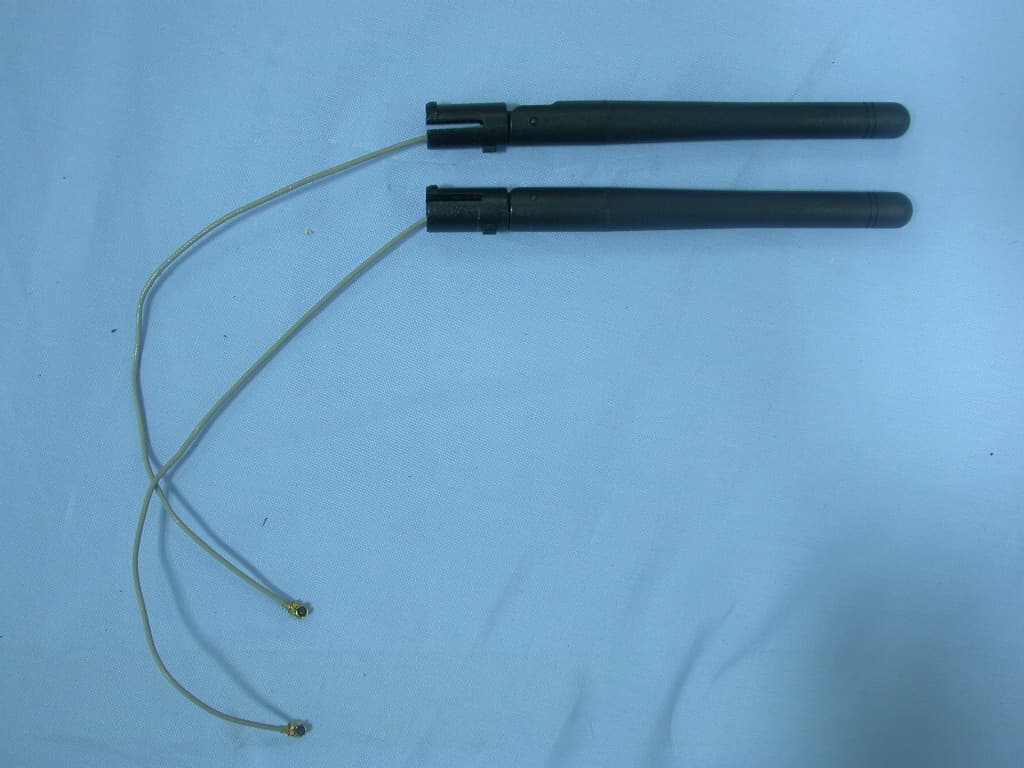
Click to zoom
Application Details
- Equipment Class
- DTS - Digital Transmission System
- Date of Grant
- Jan 28, 2007
- Application Purpose
- Original Equipment
- Date of Application
- Jan 28, 2007
- Equipment Note
- Wireless G Plus MIMO Router
- Frequency Range
- 2412.00000000 - 2462.00000000
- Company
- Belkin International, Inc.
- Country
- United States
Documents & Files
Document Text
Text extracted from the exhibit documents filed with the FCC. Open a document above to read the original.
Users Manual
User’s Manual Wireless G Plus MIMO Router F5D9230-4 Copyright The contents of this publication may not be reproduced in any part or as a whole, stored, transcribed in an information retrieval system, translated into any language, or transmitted in any form or by any means, mechanical, magnetic, electronic, optical, photocopying, manual, or otherwise, without the prior written permission. Trademarks All products, company, brand names are trademarks or registered trademarks of their respective companies. They are used for identification purpose only. Specifications are subject to be changed without prior notice. FCC Interference Statement This equipment has been tested and found to comply with the limits for a Class B digital device pursuant to Part 15 of the FCC Rules. These limits are designed to provide reasonable protection against radio interference in a commercial environment. This equipment can generate, use and radiate radio frequency energy and, if not installed and used in accordance with the instructions in this manual, may cause harmful interference to radio communications. Operation of this equipment in a residential area is likely to cause interference, in which case the user, at his own expense, will be required to take whatever measures are necessary to correct the interference. CE Declaration of Conformity This equipment complies with the requirements relating to electromagnetic compatibility, EN 55022/A1 Class B. The specification is subject to change without notice. 1 Table of Contents Chapter 1 Introduction .............................................................................. 3 Functions and Features ........................................................................ 3 Packing List ......................................................................................... 5 Chapter 2 Hardware Installation ............................................................... 6 2.1 Panel Layout .................................................................................. 6 2.2 Procedure for Hardware Installation .............................................. 7 Chapter 3 Network Settings and Software Installation............................. 9 3.1 Make Correct Network Settings of Your Computer....................... 9 Chapter 4 Configuring Wireless Broadband Router ............................... 10 4.1 Login to Configure from Wizard ................................................. 11 4.2 Status............................................................................................ 13 4.4 Basic Setting ................................................................................ 14 4.5 Forwarding Rules......................................................................... 32 4.6 Security Settings .......................................................................... 36 4.7 Advanced Settings........................................................................ 50 4.8 Toolbox ........................................................................................ 63 Appendix A TCP/IP Configuration for Windows 95/98 ........................ 68 Appendix B 802.1x Setting..................................................................... 73 Appendix C WPA-PSK and WPA .......................................................... 79 Appendix D FAQ and Troubleshooting.................................................. 92 What can I do when I have some trouble at the first time?...... 92 How do I connect router by using wireless?............................... 95 2 C C C h h h a a a p p p t t t e e e r r r 1 1 1 I I I n n n t t t r r r o o o d d d u u u c c c t t t i i i o o o n n n Congratulations on your purchase of this outstanding Wireless Broadband Router. This product is specifically designed for Small Office and Home Office needs. It provides a complete SOHO solution for Internet surfing, and is easy to configure and operate even for non-technical users. Instructions for installing and configuring this product can be found in this manual. Before you install and use this product, please read this manual carefully for fully exploiting the functions of this product. Functions and Features Router Basic functions z Auto-sensing Ethernet Switch Equipped with a 4-port auto-sensing Ethernet switch. z WAN type supported The router supports some WAN types, Static, Dynamic, PPPoE , PPTP ,L2TP, Dynamic IP with Road Runner. z Firewall All unwanted packets from outside intruders are blocked to protect your Intranet. z DHCP server supported All of the networked computers can retrieve TCP/IP settings automatically from this product. z Web-based configuring Configurable through any networked computer’s web browser using Netscape or Internet Explorer. z Virtual Server supported Enable you to expose WWW, FTP and other services on your LAN to be accessible to Internet users. z User-Definable Application Sensing Tunnel User can define the attributes to support the special applications requiring multiple connections, like Internet gaming, video conferencing, Internet telephony and so on, then this product can sense the application type and open multi-port tunnel for it. z DMZ Host supported Lets a networked computer be fully exposed to the Internet; this function is used when special application sensing tunnel feature is insufficient to allow an application to function correctly. z Statistics of WAN Supported Enables you to monitor inbound and outbound packets 3 Wireless functions z High speed for wireless LAN connection Up to 54Mbps data rate by incorporating Orthogonal Frequency Division Multiplexing (OFDM). z Roaming Provides seamless roaming within the IEEE 802.11b (11M) and IEEE 802.11g (54M) WLAN infrastructure. z IEEE 802.11b compatible (11M) Allowing inter-operation among multiple vendors. z IEEE 802.11g compatible (54M) Allowing inter-operation among multiple vendors. z Auto fallback 54M, 48M, 36M, 24M, 18M, 12M, 6M data rate with auto fallback in 802.11g mode. 11…
Text truncated - open the document above for the full version.
Users Manual
4.7.1 System Time Get Date and Time by NTP Protocol Selected if you want to Get Date and Time by NTP Protocol. Time Server Select a NTP time server to consult UTC time Time Zone Select a time zone where this device locates. Set Date and Time manually Selected if you want to Set Date and Time manually. Set Date and Time manually Selected if you want to Set Date and Time manually. Function of Buttons Sync Now: Synchronize system time with network time server Daylight Saving:Set up where the location is. 51 4.7.2 System Log This page support two methods to export system logs to specific destination by means of syslog(UDP) and SMTP(TCP). The items you have to setup including: IP Address for Syslog Host IP of destination where syslogs will be sent to. Check Enable to enable this function. E-mail Alert Enable Check if you want to enable Email alert (send syslog via email). SMTP Server IP and Port Input the SMTP server IP and port, which are concated with ':'. If you do not specify port number, the default value is 25. For example, "mail.your_url.com" or "192.168.1.100:26". Send E-mail alert to The recipients who will receive these logs. You can assign more than 1 recipient, using ';' or ',' to separate these email addresses. 52 4.7.3 Dynamic DNS To host your server on a changing IP address, you have to use dynamic domain name service (DDNS). So that anyone wishing to reach your host only needs to know the name of it. Dynamic DNS will map the name of your host to your current IP address, which changes each time you connect your Internet service provider. Before you enable Dynamic DNS, you need to register an account on one of these Dynamic DNS servers that we list in provider field. To enable Dynamic DNS click the check box next to Enable in the DDNS field. Next you can enter the appropriate information about your Dynamic DNS Server. You have to define: Provider Host Name 53 Username/E-mail Password/Key You will get this information when you register an account on a Dynamic DNS server. Example: After Dynamic DNS setting is configured, click the save button. 4.7.4 SNMP Setting In brief, SNMP, the Simple Network Management Protocol, is a protocol designed to give a user the capability to remotely manage a computer network by polling and setting terminal values and monitoring network events. Enable SNMP 54 You must check either Local or Remote or both to enable SNMP function. If Local is checked, this device will response request from LAN. If Remote is checked, this device will response request from WA N . Get Community Setting the community of GetRequest your device will response. Set Community Setting the community of SetRequest your device will accept. WAN Access IP Address IF the user wants to limit to specific the ip address to access,please input in the item.The default 0.0.0.0 and means every ip of Internet can get some information of device with snmp protocol. 55 4.7.5 Routing Routing Tables allow you to determine which physical interface address to use for outgoing IP data grams. If you have more than one routers and subnets, you will need to enable routing table to allow packets to find proper routing path and allow different subnets to communicate with each other. Routing Table settings are settings used to setup the functions of static. Dynamic Routing Routing Information Protocol (RIP) will exchange information about destinations for computing routes throughout the network. Please select RIPv2 only if you have different subnet in your network. Otherwise, please select RIPv1 if you need this protocol. Static Routing: For static routing, you can specify up to 8 routing rules. You can enter the destination IP address, subnet mask, gateway, hop for each routing rule, and then enable or disable the rule by checking or unchecking the Enable checkbox. 56 Example: Configuration on NAT Router Destination SubnetMask Gateway Hop Enabled 192.168.1.0 255.255.255.0 192.168.123.216 1 ˇ 192.168.0.0 255.255.255.0 192.168.123.103 1 ˇ So if, for example, the client3 wanted to send an IP data gram to 192.168.0.2, it would use the above table to determine that it had to go via 192.168.123.103 (a gateway), And if it sends Packets to 192.168.1.11 will go via 192.168.123.216 Each rule can be enabled or disabled individually. After routing table setting is configured, click the save button. 57 4.7.6 Schedule Rule You can set the schedule time to decide which service will be turned on or off. Select the “enable” item. Press “Add New Rule” 58 You can write a rule name and set which day and what time to schedule from “Start Time” to “End Time”. The following example configure “ftp time” as everyday 14:10 to 16:20 59 Schedule Enable Selected if you want to Enable the Scheduler. Edit To edit the schedule rule. Delete To delete the schedule rule, and the rule# of the rules behind the deleted one will decrease one automatically. Schedule Rule can be apply to Virtual server and Packet Filter, for example: 60 Exanple1: Virtual Server – Apply Rule#1 (ftp time: everyday 14:10 to 16:20) Exanple2: Packet Filter – Apply Rule#1 (ftp time: everyday 14:10 to 16:20). 61 62 4.8 Toolbox 4.8.1 System Log 63 You can View system log by clicking the View Log button 64 4.8.2 Firmware Upgrade You can upgrade firmware by clicking Firmware Upgrade button. 4.8.3 Backup Setting You can backup your settings by clicking the Backup Setting button and save it as a bin file. Once you want to restore these settings, please click Firmware Upgrade button and use the bin file you saved. 4.8.4 Reset to default 65 You can also reset this product to factory default by clicking the Reset to default button. 4.8.5 Reboot You can also reboot this product by clicking the Reboot button. 4.8.6 Miscellaneous Items MAC Address for Wake-on-LAN Wake-on-LAN is a technology that enables you to power up a networked device remotely. In order to enjoy this feature, the target device must be Wake-on-LAN enabled and you have to know the MAC address of this device, say…
Text truncated - open the document above for the full version.
Cover Letter(s)
Attestation Date: Dec. 25, 2006 FCC ID :K7SF5D9230-4V4 Product :Wireless G Plus MIMO Router Model :F5D9230-4 Statements: We don’t provide with any controls or software to allow operation outside the USA frequency band for all future applications when we sell this product in USA. Sincerely, Signature:
Cover Letter(s)
501 W. Walnut Street – Compton – California 90220 USA Confidentiality Request FCC ID : K7SF5D9230-4V4 Product : Wireless G Plus MIMO Router Model : F5D9230-4 Pursuant to Sections 0.457 and 0.459 of the Commission’s Rules, the Applicant hereby requests confidential treatment of information accompanying this Application as outlined below: Schematics Block Diagram Operational Description The above materials contain trade secrets and proprietary information not customarily released to the public. The public disclosure of these matters might be harmful to the Applicant and provide unjustified benefits to its competitors. The Applicant understands that pursuant to Rule 0.457, disclosure of this Application and all accompanying documentation will not be made before the date of the Grant for this application. Sincerely yours, Signature: Marc Matejka Manager, Document Control and Regulatory Compliance Belkin International, Inc.
External Photos
Compliance Certification Services Inc. Report No.:61018401-RP1 External Photo ( Model :F5D9230-4) Compliance Certification Services Inc. Report No.:61018401-RP1 Adapter (Model: MKD-481201000) Adapter (Model: AM-1201000D41) Compliance Certification Services Inc. Report No.:61018401-RP1 Antenna (Model: C381-510009-B)
ID Label/Location Info
Company : Belkin Corporation Model : F5D9230-4 Product : Wireless G Plus MIMO Router Wireless G Plus MIMO Router Model No: F5D9230-4 FCC IDK7SF5D9230-4V4 This device complies with part 15 of the FCC Rules. Operation is subject to the following two conditions: [1] this device may not cause harmful interference and [2] this device must accept any interference received, including interference that may cause undesired operation. S/N Made in Taiwan Label Here
Internal Photos
Compliance Certification Services Inc. Report No.:61018401-RP1 Internal Photo Compliance Certification Services Inc. Report No.:61018401-RP1 Compliance Certification Services Inc. Report No.:61018401-RP1 Internal Photo Compliance Certification Services Inc. Report No.:61018401-RP1 Compliance Certification Services Inc. Report No.:61018401-RP1 Compliance Certification Services Inc. Report No.:61018401-RP1
RF Exposure Info
Compliance Certification Services Inc. Report No: 61018401-RP1 FCC ID: K7SF5D9230-4V4 Date of Issue: November 29, 2006 Page 39 7.5 RADIO FREQUENCY EXPOSURE LIMIT Systems operating under the provisions of this section shall be operated in a manner that ensures that the public is not exposed to radio frequency energy levels in excess of the Commission's guidelines. See §15.247(i) and §1.1307(b)(1) of this chapter. EUT Specification EUT Wireless G Plus MIMO Router Frequency band (Operating) WLAN: 2.412GHz ~ 2.462GHz WLAN: 5.18GHz ~ 5.32GHz / 5.50GHz ~ 5.70GHz WLAN: 5.745GHz ~ 5.825GHz Others Device category Portable (<20cm separation) Mobile (>20cm separation) Others Exposure classification Occupational/Controlled exposure (S = 5mW/cm2) General Population/Uncontrolled exposure (S=1mW/cm2) Antenna diversity Single antenna Multiple antennas Tx diversity Rx diversity Tx/Rx diversity Max. output power 24.35dBm (272.2701 mW) Antenna gain (Max) 1.8 dBi (Numeric gain: 1.513561) Evaluation applied MPE Evaluation SAR Evaluation Remark: 1. The maximum output power is 24.35(272.2701 mW) at 2462MHz ( with 1.513561 numeric antenna gain.) 2. DTS device is not subject to routine RF evaluation; MPE estimate is used to justify the compliance. 3. For mobile or fixed location transmitters, no SAR consideration applied. The minimum separation generally be used is at least 20 cm, even if the calculations indicate that the MPE distance would be lesser. TEST RESULTS No non-compliance noted. Compliance Certification Services Inc. Report No: 61018401-RP1 FCC ID: K7SF5D9230-4V4 Date of Issue: November 29, 2006 Page 40 Calculation Given d GP E ×× = 30 & 3770 2 E S= Where E = Field Strength in Volts / meter P = Power in Watts G=Numeric antenna gain d=Distance in meters S=Power Density in milliwatts / square centimeter Combining equations and re-arranging the terms to express the distance as a function of the remaining variables yields: S GP d × ×× = 3770 30 Changing to units of mW and cm, using: P (mW) = P (W) / 1000 and d (cm) =100 * d (m) Yields S GP S GP d × ×= × ×× ×=282.0 3770 )1000/(30 100 Where d = distance in cm P = Power in mW G = Numeric antenna gain S = Power Density in mW / cm^2 Substituting the logarithmic form of power and gain using: P (mW) = 10 ^ (P (dBm) / 10) and G (numeric) = 10 ^ (G (dBi) / 10) Yields S d GP 20 )( 10 282.0 + ×= Equation 1 Where d = MPE safe distance in cm P = Power in dBm G = Antenna Gain in dBi S = Power Density Limit in mW / cm^2 Compliance Certification Services Inc. Report No: 61018401-RP1 FCC ID: K7SF5D9230-4V4 Date of Issue: November 29, 2006 Page 41 Maximum Permissible Exposure (2.4 GHz Band) EUT output power = 272.2701mW Antenna Gain = 1.8 (Numeric gain) S = 1.0 mW / cm^2 from 1.1310 Table 1 Substituting these parameters into the above Equation 1: Æ MPE Safe Distance =5.780425cm (For mobile or fixed location transmitters, the minimum separation distance is 20 cm, even if calculations indicate that the MPE distance would be less.)
Test Report
Compliance Certification Services Inc. Report No: 61018401-RP1 FCC ID: K7SF5D9230-4V4 Date of Issue: November 29, 2006 Note: This report shall not be reproduced except in full, without the written approval of Compliance Certification Services Inc. This document may be altered or revised by Compliance Certification Services Inc. personnel only, and shall be noted in the revision section of the document. Total Page: 80 Page 1 FCC 47 CFR PART 15 SUBPART C TEST REPORT For Wireless G Plus MIMO Router Model Number: F5D9230-4 Brand Name: Belkin Issued to Belkin Corporation 501 West Walnut Street Compton CA , USA Issued by Compliance Certification Services Inc. Ta i n a n L a b . No. 8, Jiu Cheng Ling, Jiaokeng Village,Sinhua Township, Tainan Hsien 712, Taiwan R.O.C. TEL: 886-6-580-2201 FAX: 886-6-580-2202 Compliance Certification Services Inc. Report No: 61018401-RP1 FCC ID: K7SF5D9230-4V4 Date of Issue: November 29, 2006 Page 2 TABLE OF CONTENTS 1 TEST RESULT CERTIFICATION....................................................................................................3 2 EUT DESCRIPTION ...........................................................................................................................4 3 TEST METHODOLOGY ....................................................................................................................5 3.1 EUT CONFIGURATION.......................................................................................................................5 3.2 EUT EXERCISE..................................................................................................................................5 3.3 GENERAL TEST PROCEDURES............................................................................................................5 3.4 FCC PART 15.205 RESTRICTED BANDS OF OPERATIONS .......................................................6 3.5 DESCRIPTION OF TEST MODES...........................................................................................................7 4 INSTRUMENT CALIBRATION........................................................................................................7 5 FACILITIES AND ACCREDITATIONS ..........................................................................................8 5.1 FACILITIES.........................................................................................................................................8 5.2 EQUIPMENT.......................................................................................................................................8 5.3 LABORATORY ACCREDITATIONS AND LISTING.................................................................................8 5.4 TABLE OF ACCREDITATIONS AND LISTINGS......................................................................................9 6 SETUP OF EQUIPMENT UNDER TEST .......................................................................................10 6.1 SETUP CONFIGURATION OF EUT......................................................................................................10 6.2 SUPPORT EQUIPMENT ...............................................................................................................10 7 FCC PART 15.247 REQUIREMENTS.............................................................................................11 7.1 6DB BANDWIDTH ........................................................................................................................11 7.2 PEAK POWER...................................................................................................................................17 7.3 BAND EDGES MEASUREMENT ................................................................................................23 7.4 PEAK POWER SPECTRAL DENSITY...................................................................................................33 7.5 RADIO FREQUENCY EXPOSURE........................................................................................................39 7.6 SPURIOUS EMISSIONS ...............................................................................................................42 7.7 POWER LINE CONDUCTED EMISSIONS.............................................................................................72 8 APPENDIX 1 PHOTOGRAPHS OF TEST SETUP .......................................................................77 Compliance Certification Services Inc. Report No: 61018401-RP1 FCC ID: K7SF5D9230-4V4 Date of Issue: November 29, 2006 Page 3 1 TEST RESULT CERTIFICATION Applicant :Belkin Corporation Address :501 West Walnut Street Compton CA , USA Manufacture :Advance Multimedia Internet Technology Inc. Address :No.32 , Hwan-Gong Rd. Yung Kang City , Tainan Hsien , Taiwan Equipment Under Test :Wireless G Plus MIMO Router Model Number :F5D9230-4 Brand Name :Belkin Date of Test :October 23, 2006~ October 31, 2006 APPLICABLE STANDARDS STANDARD TEST RESULT FCC 47 CFR Part 15 Subpart C No non-compliance noted We hereby certify that: The above equipment was tested by Compliance Certification Services Inc. The test data, data evaluation, test procedures, and equipment configurations shown in this report were made in accordance with the procedures given in ANSI C63.4 and the energy emitted by the sample EUT tested as described in this report is in compliance with the requirements of FCC Rules Part 15.207, 15.209, 15.247. The test results of this report relate only to the tested sample EUT identified in this report. Approved by: Reviewed by: November 29, 2006 November 29, 2006 Alex Chiu Jeter Wu Manager Section Manager Compliance Certification Services Inc. Compliance Certification Services Inc. Compliance Certification Services Inc. Report No: 61018401-RP1 FCC ID: K7SF5D9230-4V4 Date of Issue: November 29, 2006 Page 4 2 EUT DESCRIPTION Product Wireless G Plus MIMO Router Model Number F5D9230-4 Brand Name Belkin Model Discrepancy N/A Power Supply Power by Adaptor Adapter…
Text truncated - open the document above for the full version.
Test Setup Photos
Compliance Certification Services Inc. Report No: 61018401-RP1 FCC ID: K7SF5D9230-4V4 Date of Issue: November 29, 2006 Page 77 8 APPENDIX 1 PHOTOGRAPHS OF TEST SETUP RADIATED EMISSION MEASUREMENT SETUP Compliance Certification Services Inc. Report No: 61018401-RP1 FCC ID: K7SF5D9230-4V4 Date of Issue: November 29, 2006 Page 78 RADIATED RF MEASUREMENT SETUP Compliance Certification Services Inc. Report No: 61018401-RP1 FCC ID: K7SF5D9230-4V4 Date of Issue: November 29, 2006 Page 79 Compliance Certification Services Inc. Report No: 61018401-RP1 FCC ID: K7SF5D9230-4V4 Date of Issue: November 29, 2006 Page 80 Conducted Emission Set Up Photos END OF REPORT
Contact Information
Applicant
Jay TU(Manager, Regulatory Compliance)
Test Firm
Compliance Certification Services Inc.Alex Chiu
Technical Specifications
| # | Rule Parts | Frequency Range | Power Output |
|---|---|---|---|
| 1 | 15C | 2.41 GHz - 2.46 GHz | 272.00 mW |
Other Applications from Belkin International, Inc.
K7S-CAB029
Aug 11, 2026SureFind Loop Cable Tag
Equipment Class
DTS - Digital Transmission SystemK7SBPD024
Aug 10, 2026UltraCharge Pro Slim Magnetic Power Bank 5K with BoostSolid Cell
Equipment Class
DCD - Part 15 Low Power Transmitter Below 1705 kHzK7SMMA016
Jul 22, 2026SureFind Wallet Stand
Equipment Class
DTS - Digital Transmission SystemK7SMMA015
Jul 10, 2026SureFind
Equipment Class
DTS - Digital Transmission SystemK7SAUC018
Jun 17, 2026SoundForm Dot ANC Earbuds, SoundForm Dot Earbuds
Equipment Class
DTS - Digital Transmission System