K7SF7D1301V1802.11 b/g/n Router
Belkin International, Inc.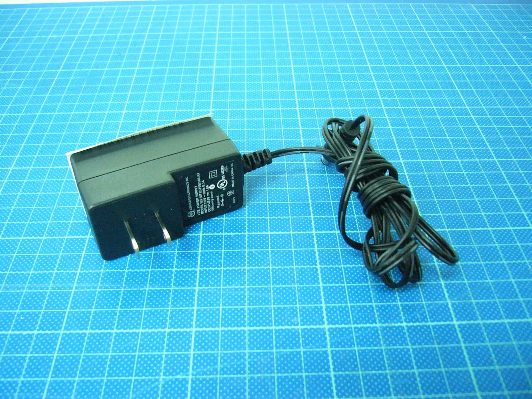
Click to zoom
Application Details
- Equipment Class
- DTS - Digital Transmission System
- Date of Grant
- Feb 22, 2010
- Application Purpose
- Original Equipment
- Date of Application
- Feb 22, 2010
- Equipment Note
- 802.11 b/g/n Router
- Frequency Range
- 2422.00000000 - 2452.00000000
- Company
- Belkin International, Inc.
- Country
- United States
Documents & Files
Document Text
Text extracted from the exhibit documents filed with the FCC. Open a document above to read the original.
Users Manual
23525_8820-00370_F7D1301 v1_Basic Router_0208 change ROUTER USER MANUAL F7D1301 V1 v1 TABLE OF CONTENTS Getting Started What’s in the Box Initial Setup Advanced Tools & Settings The Belkin Router Manager Manual Setup Using Your Browser Adding Computers to Your Network Getting to Know Your Router Front Panel Back Panel Technical Details Technical Features System Requirements Troubleshooting, Support, and Warranty Troubleshooting Technical Support Belkin International, Inc., Limited 2-Year Product Warranty Regulatory Information FCC Statement 23525_8820-00370_F7D1301 v1_Basic Router_0208 change Getting Started What’s in the Box Basic Wireless Router Ethernet cable (attached to router) Power supply (attached to router) Network information card (attached to router) Belkin Setup CD with User Manual Initial Setup Where to Place Your Router For the best results, place the Router next to your modem in an open location away from large metal objects and magnets such as those found in speakers. Raising the Router above floor level can improve the strength of your wireless signal. How to Set It Up [R BASIC/SURF SETUP DIAGRAM basicsurf setup.ai] 1) Connect your Router’s Ethernet cable to your modem’s Ethernet port (on the back of your modem). This port might be labeled differently on your particular modem. If you are adding a Router for the first time, this port may be connected to your computer by an Ethernet cable. It is OK to disconnect your computer and plug the Router into the modem instead. 2) Plug the Router’s power supply into a wall outlet. 3) Put the CD into your computer. If the CD doesn’t open automatically, please browse to your CD drive and double- click on the Belkin Setup CD icon. [SCREENSHOT OF SETUP MENU setup menu.png] 4) Click the Setup icon on the CD menu. 23525_8820-00370_F7D1301 v1_Basic Router_0208 change [SCREENSHOT OF NETWORK INFO CARD SCREEN setup netinfo card.png] 5) After a brief installation, the setup software will ask you for the network name and password from the network information card that is attached to your Router. Store the card under the base of your Router for future reference. [SCREENSHOT OF SUCCESS setup success.png] 6) A progress screen will appear while additional software is installed. This may take a few minutes to complete. Once finished, a “Success” message will appear indicating that you are connected to the Internet via your new Belkin Router. During setup you may be asked for additional information. You may need to enter a username and password provided by your ISP. This username and password is likely to be found on materials that came from your ISP when you signed up for service. If necessary, you may need to contact your ISP to retrieve your username and password. If you have a static IP address, you may need to enter additional information also provided by your ISP. If your computer doesn’t have a wireless adapter, or the setup software is unable to control it, you may be asked to connect your computer to the Router with a network cable. Advanced Tools & Settings [SCREENSHOT OF ADVANCED MENU setup advanced2.png] After the initial setup is complete, you have the option to change settings like your network name, security type, and password. To make these changes and others, click on the Advanced Tools icon at the CD Setup menu and select one of the following settings that you would like to change: Network Name & Security Personalize your network name (SSID), password, and strength of wireless security. 23525_8820-00370_F7D1301 v1_Basic Router_0208 change Internet Service Provider & Login Settings Have you moved or changed Internet Service Providers? If you’d like to change these settings without running through the setup process again, this is the place. The Belkin Router Manager [BASIC/ SCREENSHOT OF TRAY APP MENU (TBD)] The Belkin Router Manager appears in your system tray (Windows) or menu bar (Mac). Its icon indicates the current status of your Router and also allows you to access your Router’s settings to make changes. It also provides quick access to software that came bundled with your Router. To access the Router settings, click on the icon and select from the menu that appears. The status of your Router is shown by the Belkin Router Manager icon, which closely mimics the light on the front of the Router. Green: You are connected to your Belkin Router and it is connected to the Internet. Amber: You are connected to your Belkin Router, but it is not connected to the Internet. 23525_8820-00370_F7D1301 v1_Basic Router_0208 change Manual Setup Using Your Browser [ZOOMED SCREENSHOT OF ADDRESS BAR address bar.png] In your browser, type “http://router” (you do not need to type in anything else such as “www”). Then press the Enter key. If you’re still having trouble running the manual setup option, type “192.168.2.1” in your browser (you do not need to type in anything else such as “http://” or “www”). Then press the Enter key. Adding Computers to Your Network Wireless devices such as computers, network printers, and gaming systems can connect to your Router with a few simple steps. Using the CD 1) Put the Setup CD into your computer. If the CD doesn’t open automatically, browse to your CD drive and open the Belkin Setup CD icon. 2) Click the Setup icon on the CD menu. 3) After a brief installation, the setup software will ask you for the network name and password from the network information card that came with your Router. This card is most likely now located underneath the foot of your Router in the provided card slot. 4) A progress screen will appear while additional software is installed. This may take a few minutes to complete. Once finished, a “Success” message will appear indicating that you are connected to the Internet via your new Belkin Router. Note: The setup software runs only on Windows and Mac OS X systems. Manually If you choose not to use the included Setup CD for adding additional computers or wireless devices, you can manually …
Text truncated - open the document above for the full version.
Users Manual
Basic wireless router User Manual F7D1301 8820 - 00370 TaBle Of COnTenTs Getting started . . . . . . . . . . . . . . . . . . . . . . . . . . . . . . . . . . . . . . . . . . .1 What’s in the Box . . . . . . . . . . . . . . . . . . . . . . . . . . . . . . . . . . . . . . . . . . . . .1 Initial Setup . . . . . . . . . . . . . . . . . . . . . . . . . . . . . . . . . . . . . . . . . . . . . . . . . .1 Advanced Tools & Settings . . . . . . . . . . . . . . . . . . . . . . . . . . . . . . . . . . . . .6 The Belkin Router Manager . . . . . . . . . . . . . . . . . . . . . . . . . . . . . . . . . . . .7 Manual Setup Using Your Browser . . . . . . . . . . . . . . . . . . . . . . . . . . . . . .8 Adding Computers to Your Network . . . . . . . . . . . . . . . . . . . . . . . . . . . . .9 Getting to Know Your Router . . . . . . . . . . . . . . . . . . . . . . . . . . . . . .11 Front Panel . . . . . . . . . . . . . . . . . . . . . . . . . . . . . . . . . . . . . . . . . . . . . . . . .11 Back Panel . . . . . . . . . . . . . . . . . . . . . . . . . . . . . . . . . . . . . . . . . . . . . . . . .12 Technical Details . . . . . . . . . . . . . . . . . . . . . . . . . . . . . . . . . . . . . . . .13 Technical Features . . . . . . . . . . . . . . . . . . . . . . . . . . . . . . . . . . . . . . . . . .13 System Requirements . . . . . . . . . . . . . . . . . . . . . . . . . . . . . . . . . . . . . . . .14 Troubleshooting, support, and Warranty . . . . . . . . . . . . . . . . . . .15 Troubleshooting . . . . . . . . . . . . . . . . . . . . . . . . . . . . . . . . . . . . . . . . . . . . .15 Technical Support . . . . . . . . . . . . . . . . . . . . . . . . . . . . . . . . . . . . . . . . . . .22 Belkin International, Inc ., Limited 2-Year Product Warranty . . . . . . . . .23 Regulatory Information . . . . . . . . . . . . . . . . . . . . . . . . . . . . . . . . . . .26 FCC Statement . . . . . . . . . . . . . . . . . . . . . . . . . . . . . . . . . . . . . . . . . . . . . .26 1 GeTTInG sTaRTeD What’s in the Box Basic Wireless Router Ethernet cable (attached to router) Power supply (attached to router) Network information card (attached to router) Belkin Setup CD with User Manual Initial setup Where to Place Your Router For the best results, place the Router next to your modem in an open location away from large metal objects and magnets such as those found in speakers . Raising the Router above floor level can improve the strength of your wireless signal . 2 GeTTInG sTaRTeD 3 modem 1 2 How to set It Up 3 GeTTInG sTaRTeD 1 . Connect your Router’s Ethernet cable to your modem’s Ethernet port (on the back of your modem) . This port might be labeled differently on your particular modem . If you are adding a Router for the first time, this port may be connected to your computer by an Ethernet cable . It is OK to disconnect your computer and plug the Router into the modem instead . 2 . Plug the Router’s power supply into a wall outlet . 3 . Put the CD into your computer . If the CD doesn’t open automatically, please browse to your CD drive and double-click on the Belkin Setup CD icon . 4 . Click the Setup icon on the CD menu . Setup 4 GeTTInG sTaRTeD 5 . After a brief installation, the setup software will ask you for the network name and password from the network information card that is attached to your Router . Store the card under the base of your Router for future reference . 5 GeTTInG sTaRTeD 6 . A progress screen will appear while additional software is installed . This may take a few minutes to complete . Once finished, a “Success” message will appear indicating that you are connected to the Internet via your new Belkin Router . During setup you may be asked for additional information . You may need to enter a username and password provided by your ISP . This username and password is likely to be found on materials that came from your ISP when you signed up for ser vice . If necessar y, you may need to contact your ISP to retrieve your username and password . If you have a static IP address, you may need to enter additional information also provided by your ISP . If your computer doesn’t have a wireless adapter, or the setup software is unable to control it, you may be asked to connect your computer to the Router with a network cable . 6 GeTTInG sTaRTeD advanced Tools & settings After the initial setup is complete, you have the option to change settings like your network name, security type, and password . To make these changes and others, click on the Advanced Tools icon at the CD Setup menu and select one of the following settings that you would like to change: network name & security – Personalize your network name (SSID), password, and strength of wireless security . Internet service Provider & login settings – Have you moved or changed Internet Service Providers? If you’d like to change these settings without running through the setup process again, this is the place . 7 GeTTInG sTaRTeD The Belkin Router Manager Belkin.2234 Router Settings User Manual Check for Updates Options Exit The Belkin Router Manager appears in your system tray (Windows) or menu bar (Mac) . Its icon indicates the current status of your Router and also allows you to access your Router’s settings to make changes . It also provides quick access to software that came bundled with your Router . To access the Router settings, click on the icon and select from the menu that appears . The status of your Router is shown by the Belkin Router Manager icon, which closely mimics the light on the front of the Router . Green: You are connected to your Belkin Router and it is connected to the Internet . amber: You are connected to your Belkin Router, but it is not connected to the Internet . 8 GeTTInG sTaRTeD In your browser, type “http://router” (you do not need to type in anything else such as “www”) . Then press the Enter key . If you’re still having trouble running the manual setup option, type “192 .168 .2 .1” in your browser (you do not need to t…
Text truncated - open the document above for the full version.
Cover Letter(s)
501 W. Walnut Street – Compton – California 90220 USA Attestation for FCC Declaration of Conformity FCC ID: K7SF7D1301V1 Date: 2009-12-03 Please be notified that we, the undersigned, Belkin International Inc. declares that the product which bears the above FCC ID is also compliant with the FCC requirements for DoC. The test report number supporting the DoC is TS09120012-EME. Testing in regards to this report was done by Intertek Testing Service Taiwan Ltd., located at No. 11, Lane 275, Ko Nan 1st Street, Shiang-Shan District, Hsinchu Taiwan, which has been accredited in accordance to all of the requirements of 47CFR 2.948 (d) and (e) of the FCC rules and KDB349827. Sincerely, Printed name: Daniel Wesey Position: EMC Regulatory Compliance Engineer Belkin International Inc. Tel: 1-310-604-2315 Fax: 1-310-898-1503 Email: [email protected]
Cover Letter(s)
501 W. Walnut Street – Compton – California 90220 USA Confidentility Letter (Permanent) Attention: Application Examiner Re: Request for confidentiality Applicant: Belkin International Inc. FCC ID: K7SF7D1301V1 To whom it may concern, Request is hereby submitted by Belkin International Inc. to withhold permanently from public review certain portions of the application for equipment certification for the referenced FCC identifiers. This request for confidentiality is made pursuant to 47 CFR 0.457(d) of the FCC Rules. In particular, the following sections of the application are to be kept permanently confidential: [Select one or more of items below, as appropriate] • Schematics • Detailed Block diagrams • Detailed Operational/Functional Description Rationale for request for confidentiality: Belkin International Inc. has invested considerable time and materials in research and development to produce the referenced product. Disclosure of the permanently confidential portions of this application to competitors would not only give them significant competitive advantages in developing similar products, but would also disclose successful implementation of unpublished, leading edge technology developed by us. If you have questions or need further information, please contact the undersigned. Sincerely, Title: EMC Regulatory Compliance Engineer Company name: Belkin International Inc. Date: 2009/12/3
Cover Letter(s)
Attn: Director of Certification Authority to Act as Agent I appoint __Intertek Testing Service Taiwan Ltd._____ to act as our agent in the preparation of this application for equipment certification. I certify that submitted documents properly describe the device or system for which equipment certification is sought. I also certify that each unit manufactured, imported or marketed, as defined in Industry Canada’s regulations will have affixed to it a label identical to that submitted for approval with this application. For instances where our authorized agent signs the application for certification on our behalf, I acknowledge that all responsibility for complying with the terms and conditions for Certification, as specified by American TCB, still resides with ___( applicant name and address)___. Dated this 3 day of December, 2009 Agency Agreement Expiration Date: (Typically 8-12 months) By: __________________________ Daniel Wesey (Signature) (Print name) Title: EMC Regulatory Compliance Engineer email: [email protected] On behalf of: Belkin International Inc. (Company Name) Telephone: +1-310-604-2315
Cover Letter(s)
501 W. Walnut Street – Compton – California 90220 USA Letter of Agency "I, an officer of Belkin International Inc. do hereby authorize Rico Deng, who is Senior Engineer in Intertek Testing Services Taiwan Ltd. to act on our behalf in front of the Federal Communications Commission with respect to all matters relating to certification of equipment under Part 15 and Part 18 of the FCC Rules until further notice." I further certify that no party (as defined in §1.2002(b) of CFR 47, 1992) to this application, including myself, is subject to a denial of federal benefits, that includes FCC benefits, pursuant to Section 5301 of the Anti-Drug Abuse Act of 1988, 21 U.S.C.,853(a). By: Daniel Wesey Signature Printed Title: EMC Regulatory Compliance Engineer Date: 2009-12-03
External Photos
Photo 1: External photo of EUT Photo 2: External photo of EUT F7D1301 v1 F7D1301 v1 Photo 3: External photo of Adapter Photo 4: External photo of Adapter F7D1301 v1 F7D1301 v1 Photo 5: External photo of Adapter Photo 6: External photo of Adapter F7D1301 v1 F7D1301 v1
ID Label/Location Info
FCC ID Label Location 88*32mm
Internal Photos
Photo 1: Internal photo of EUT Photo 2: Internal photo of EUT F7D1301 v1 F7D1301 v1 Photo 3: Internal photo of EUT Photo 4: Internal photo of EUT F7D1301 v1 F7D1301 v1 Antenna Photo 5: Internal photo of EUT Photo 6: Internal photo of EUT F7D1301 v1 F7D1301 v1
RF Exposure Info
FCC ID. : K7SF7D1301V1 Report No.: TS09120014-EME Page 1 of 6 Maximum Permissible Exposure (MPE) Evaluation Report Report No. : TS09120014-EME Model No. : F7D1301 v1 Issued Date : Feb. 04, 2010 Applicant: Belkin International Inc. 501 West Walnut Street Compton, CA 90220, USA Test Method/ Standard: FCC 1.1310 Test By: Intertek Testing Services Taiwan Ltd. No. 11, Lane 275, Ko-Nan 1 Street, Chia-Tung Li, Shiang-Shan District, Hsinchu City, Taiwan It may be duplicated completely for legal use with the allowance of the applicant. It shall not be reproduced except in full, without the written approval of Intertek Laboratory. The test result(s) in this report only applies to the tested sample(s). The test report was prepared by: Sign on File Julie Liu/ Assistant These measurements were taken by: Sign on File Leon Cheng/ Engineer The test report was reviewed by: Name Jacky Chen Title Engineer FCC ID. : K7SF7D1301V1 Report No.: TS09120014-EME Page 2 of 6 Table of Contents Summary of Tests ............................................................................................................. 3 1. Introduction .................................................................................................................. 4 2. RF Exposure Limit ....................................................................................................... 4 3. RF Exposure calculations ............................................................................................. 5 4 Description of EUT ....................................................................................................... 5 4. Test results .................................................................................................................... 6 FCC ID. : K7SF7D1301V1 Report No.: TS09120014-EME Page 3 of 6 Summary of Tests MPE Evaluation meet FCC OET No. 65: 1997, IEEE C95.1-2005 FCC ID: K7SF7D1301V1 Test Reference Results MPE Evaluation FCC Guidelines for Human Exposure IEEE C95.1 Complies FCC ID. : K7SF7D1301V1 Report No.: TS09120014-EME Page 4 of 6 1. Introduction The EUT operates in the 2.4 GHz ISM band. Due to the EUT (include antenna) at its normal operation distance is at least 20 cm from the human body, the EUT was defined as a Mobile Device. The reason to do the MPE Evaluation is to avoid the RF hazard to human body. The maximum output power and gain of the antenna were used to calculate the limited Power density (S) at 20 cm distance away from the product. The limit for Maximum Permissible Exposure (MPE) specified in FCC 1.1310 are followed. According to 1.1307 (b)(1), systems operating under the provisions of this section shall be operated in a manner that ensure that the public is not exposed to radio frequency energy level in excess of the Commission’s guideline. 2. RF Exposure Limit According to FCC 1.1310: The criteria listed in the following table shall be used to evaluate the environmental impact of human exposure to radio-frequency (RF) radiation as specified in 1.1307(b). Limits for Maximum Permissible Exposure (MPE) Frequency Range (MHz) Electric Field Strength (V/m) Magnetic Field Strength (A/m) Power Density (mW/cm 2 ) Average Time (minutes) (A) Limits for Occupational / Control Exposures 30-300 61.4 0.163 1.0 6 300-1500 - - F/300 6 1500-100,000 - - 5 6 (B) Limits for General Population / Uncontrolled Exposure 30-300 27.5 0.073 0.2 30 300-1500 - - F/1500 30 1500-100,000 - - 1.0 30 F= Frequency in MHz FCC ID. : K7SF7D1301V1 Report No.: TS09120014-EME Page 5 of 6 3. RF Exposure calculations From §FCC 1.1310 table 1, the maximum permissible RF exposure for an uncontrolled environment is 1mW/(cm 2 ) Power density (S) is calculated by the following formula: S = (P * G)/4 πR 2 where, S = Power density (mW/cm 2 ) P = Output power to antenna (mW) R = Distance between radiating structure and observation point (cm) G = Gain of antenna in numeric π = 3.1416 Example: Assume a mobile device operates at 2412MHz and its maximum output power is 50mW, and the maximum gain of antenna is 1 (numeric) /0dBi. then the power density (S) = (50 * 1)/4*π*20 2 = 0.0995 W/m 2 4 Description of EUT The EUT is a Router, which is an 802.11b/g/n MIMO product with one transmitters and one receivers and was defined as information technology equipment. The EUT has 802.11n function which can transmitter independently and simultaneous transmit. 4.1 Antenna description The EUT uses a permanently connected antenna. Antenna Gain: 2 dBi max Antenna Type: PIFA antenna Connector Type: N/A FCC ID. : K7SF7D1301V1 Report No.: TS09120014-EME Page 6 of 6 4. Test results Mode Channel Frequency (MHz) Antenna Gain (numeric) Output power to antenna (mW) Power density (mW/cm2) Limit of power density (mW/cm2) Distance (cm) 1 2412 1.58 121.90 0.038435288 1.0 20 6 2437 1.58 110.66 0.034892344 1.0 20 802.11b 11 2462 1.58 101.16 0.031895554 1.0 20 1 2412 1.58 103.51 0.032638496 1.0 20 6 2437 1.58 219.79 0.069299507 1.0 20 802.11g 11 2462 1.58 118.85 0.037474008 1.0 20 1 2412 1.58 70.79 0.022321848 1.0 20 6 2437 1.58 211.35 0.066639257 1.0 20 802.11n HT20 11 2462 1.58 117.22 0.036959845 1.0 20 3 2422 1.58 44.16 0.013922914 1.0 20 6 2437 1.58 130.32 0.041089433 1.0 20 802.11n HT40 9 2452 1.58 108.39 0.034176701 1.0 20 The Notice in Installation Manual has been stated as below: While installing and operating this transmitter, the radio frequency exposure limit of 1 mW/ (cm 2 ) may be exceeded at distances close to the transmitter. therefore, the user must maintain a minimum distance of 20 cm from the device at all time.
Test Report
FCC ID. : K7SF7D1301V1 Report No.: TS09120013-EME Page 1 of 71 EMC TEST REPORT Report No. : TS09120013-EME Model No. : F7D1301 v1 Issued Date : Feb. 04, 2010 Applicant: Belkin International Inc. 501 West Walnut Street Compton, CA 90220, USA Test Method/ Standard: 47 CFR FCC Part 15.247 & ANSI C63.4 2003 Test By: Intertek Testing Services Taiwan Ltd. No. 11, Lane 275, Ko-Nan 1 Street, Chia-Tung Li, Shiang-Shan District, Hsinchu City, Taiwan It may be duplicated completely for legal use with the allowance of the applicant. It shall not be reproduced except in full, without the written approval of Intertek Laboratory. The test result(s) in this report only applies to the tested sample(s). The test report was prepared by: Sign on File Julie Liu/ Assistant These measurements were taken by: Sign on File Leon Cheng/ Engineer The test report was reviewed by: Name Jacky Chen Title Engineer FCC ID. : K7SF7D1301V1 Report No.: TS09120013-EME Page 2 of 71 Table of Contents 1. Summary of Test Data................................................................................................................. 3 2. General Information.................................................................................................................... 4 3. Maximum 6 dB Bandwidth......................................................................................................... 7 4. Maximum Output Power........................................................................................................... 15 5. Power Spectral Density............................................................................................................. 17 6. RF Antenna conducted Spurious............................................................................................... 25 7. Radiated Spurious Emission ..................................................................................................... 44 8. Emission on Band Edge ............................................................................................................ 54 Appendix A: Test Equipment List................................................................................................. 71 FCC ID. : K7SF7D1301V1 Report No.: TS09120013-EME Page 3 of 71 1. Summary of Test Data Test/Requirement Description Applicable Rule Result Minimum 6 dB Bandwidth 15.247(a)(2) Pass Maximum Output Power 15.247(b) Pass Power Spectral Density 15.247(e) Pass RF Antenna Conducted Spurious 15.247(d) Pass Radiated Spurious Emission 15.247(d), 15.205, 15.209 Pass Emission on the Band Edge 15.247(d) Pass AC Power Line Conducted Emission 15.207 Pass FCC ID. : K7SF7D1301V1 Report No.: TS09120013-EME Page 4 of 71 2. General Information Identification of the EUT Product: Router Model No.: F7D1301 v1 FCC ID.: K7SF7D1301V1 Frequency Range: 1. 2412 MHz to 2462 MHz for 802.11b/g/n HT20 2. 2422 MHz to 2452 MHz for 802.11n HT40 Channel Number: 1. 11 channels for 802.11b/g/n HT20 2. 7 channels for 802.11n HT40 Rated Power: 1. DC 9 V from adapter model: MT12-Y090100-A1 I/P Voltage: 100-240 Vac, 50/60Hz 2. DC 9 V from adapter model: DSA-12GX-09 FUS 090090 I/P Voltage: 100-240 Vac, 50/60Hz Power Cord: N/A Data Cable: RJ-45 UTP Cat.5 10meter × 1 Sample Received: Nov. 18, 2009 Test Date(s): Nov. 18, 2009 ~ Jan. 07, 2010 Note 1: This report is for the exclusive use of Intertek's Client and is provided pursuant to the agreement between Intertek and its Client. Intertek's responsibility and liability are limited to the terms and conditions of the agreement. Intertek assumes no liability to any party, other than to the Client in accordance with the agreement, for any loss, expense or damage occasioned by the use of this report. Only the Client is authorized to permit copying or distribution of this report and then only in its entirety. Any use of the Intertek name or one of its marks for the sale or advertisement of the tested material, product or service must first be approved in writing by Intertek. The observations and test results in this report are relevant only to the sample tested. This report by itself does not imply that the material, product, or service is or has ever been under an Intertek certification program. Note 2: When determining the test conclusion, the Measurement Uncertainty of test has been considered. FCC ID. : K7SF7D1301V1 Report No.: TS09120013-EME Page 5 of 71 Description of EUT The EUT is a Router, which is an 802.11b/g/n product with one transmitter and one receiver and was defined as information technology equipment. Antenna description The EUT uses a permanently connected antenna. Antenna Gain: 2 dBi max Antenna Type: PIFA antenna Connector Type: N/A FCC ID. : K7SF7D1301V1 Report No.: TS09120013-EME Page 6 of 71 Operation mode The EUT was supplied with DC 9 V from adapter (Test voltage: 120 Vac, 60 Hz). The EUT was transmitted continuously during the test. With individual verifying, the maximum output power was found at 1 Mbps data rate for 802.11b mode, 6 Mbps data rate for 802.11g mode, 6.5 Mbps data rate for 802.11n HT20 mode and 13.5 Mbps data rate for 802.11n HT40 mode. The final tests were executed under these conditions and recorded in this report individually. 802.11b ch6 chain0 802.11n HT20 ch6 chain0 Data rate(Mbps) PK(dBm) Data rate(Mbps) PK(dBm) 1 20.44 6.5 23.25 2 20.35 13 23.18 5.5 20.38 19.5 23.10 11 20.22 26 23.15 39 23.07 802.11g ch6 chain0 52 22.95 Data rate(Mbps) PK(dBm) 58.5 22.87 6 23.42 65 22.80 9 23.36 12 23.30 802.11n HT40 ch6 chain0 18 23.32 Data rate(Mbps) PK(dBm) 24 23.15 13.5 21.15 36 23.08 27 21.08 48 22.95 40.5 21.03 54 22.97 54 20.91 81 20.98 108 20.85 121.5 20.80 135 20.77 FCC ID. : K7SF7D1301V1 Report No.: TS09120013-EME Page 7 of 71 3. Maximum 6 dB Bandwidth Name of Test Maximum 6 dB Bandwidth Base Standard FCC 15.247 (a)(2) Test Result: Complies Measurement Data: See Table 1 & plots below Method of Measurement: Reference FCC document: KDB558074 A portion of the transmitted signal is coupled to a Spect…
Text truncated - open the document above for the full version.
Test Setup Photos
Photo 1: Conducted Emission Test Set-up photo Photo 2: Conducted Emission Test Set-up photo F7D1301 v1 F7D1301 v1
Test Setup Photos
Photo 1: Radiated Emission Test set-up photo Photo 2: Radiated Emission Test set-up photo F7D1301 v1 F7D1301 v1
Contact Information
Applicant
Jay TU(Manager, Regulatory Compliance)
Technical Contact
Intertek Testing Services Taiwan Ltd.Rico Deng
[email protected](+886)-3-519-1411
No. 11, Lane 275, Ko-Nan 1 Street,Chia-Tung Li, · Hsinchu · Taiwan
Non-Technical Contact
Intertek Testing Services Taiwan Ltd.Rico Deng
[email protected](+886)-3-519-1411
Test Firm
Intertek Testing Services Taiwan Ltd.Alpha Liu
Technical Specifications
| # | Rule Parts | Frequency Range | Power Output |
|---|---|---|---|
| 2 | 15C | 2.42 GHz - 2.45 GHz | 130.00 mW |
Other Applications from Belkin International, Inc.
K7S-CAB029
Aug 11, 2026SureFind Loop Cable Tag
Equipment Class
DTS - Digital Transmission SystemK7SBPD024
Aug 10, 2026UltraCharge Pro Slim Magnetic Power Bank 5K with BoostSolid Cell
Equipment Class
DCD - Part 15 Low Power Transmitter Below 1705 kHzK7SMMA016
Jul 22, 2026SureFind Wallet Stand
Equipment Class
DTS - Digital Transmission SystemK7SMMA015
Jul 10, 2026SureFind
Equipment Class
DTS - Digital Transmission SystemK7SAUC018
Jun 17, 2026SoundForm Dot ANC Earbuds, SoundForm Dot Earbuds
Equipment Class
DTS - Digital Transmission System