K7SF8E815MSERF Wireless Mouse
Belkin International, Inc.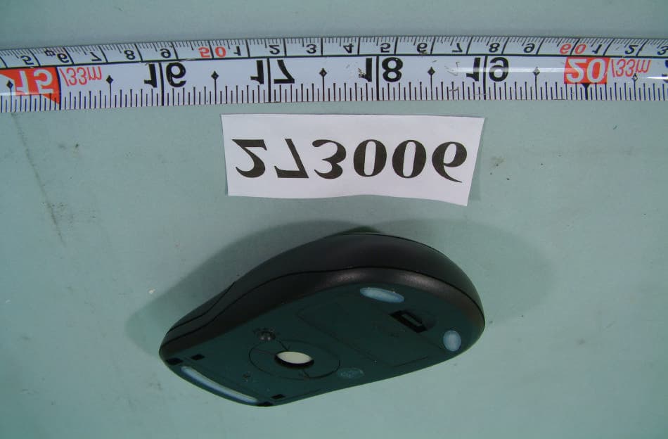
Click to zoom
Application Details
- Equipment Class
- DXX - Part 15 Low Power Communication Device Transmitter
- Date of Grant
- Oct 28, 2002
- Application Purpose
- Original Equipment
- Date of Application
- Oct 28, 2002
- Equipment Note
- RF Wireless Mouse
- Frequency Range
- 26.96000000 - 27.28000000
- Company
- Belkin International, Inc.
- Country
- United States
Documents & Files
Document Text
Text extracted from the exhibit documents filed with the FCC. Open a document above to read the original.
Users Manual
Belkin Wireless Desktop User Manual FCC ID: K7SF8E815MSE P/N:F8E815-BNDL Belkin Components RF Keyboard and Mouse Combo I. Installation of the hardware 1. First make sure the computer is turned off. 2. Connect the receiver to your computer. The receiver has a two head connector for the Keyboard and Mouse connections. Purple is for Keyboard and Green is for mouse. They also have pictures on the top to identify them. Please make sure you put them in the correct ports on your computer. Your computer should either have the same color scheme or there will be a picture next to the plug to identify it. 3. Next install the batteries into your Keyboard and Mouse. Now you may turn your computer on. 4. The receiver was set by the factory to automatically scan for the Keyboard and mouse once the computer is turned on. So you should not have to do anything more to get the Keyboard and Mouse to work. 5. If it does not work automatically here are some things to check • If the Keyboard and/or mouse are not working, make sure that you see the light on both start blinking when you push any of the buttons or move the mouse. Note: if you do not get any lights flashing then you should check to make sure you have the batteries in correctly or may be they are bad (try replacing them). • Also check to see if when the light flashes on the keyboard and mouse that it also makes the light on the receiver flash too. If there is no response on the receiver, then that means they are not connecting. Push the reset button on the receiver. Then within 5 seconds push the reset button on the mouse or keyboard. Note: if you have to do this for both keyboard and mouse, do them separately. Figure’s 1 through 3 show where the reset button and the battery compartment are located at. Below is the installation procedure step by step and you can also refer to the label on the back of keyboard to install the devices correctly when they are not working. II. Software installation. l Warning: If you have previously installed other keyboard or mouse drivers on your PC, please uninstall them first. Note: Make sure the Keyboard and Mouse is functioning correct before you continue with the Software installation. The software does not get the Keyboard and mouse working. It only adds extra features. 1. Make sure the computer is on 2. Insert the CD into the computer. 3. The First screen that comes up tells you to remove any software that may still be install from another Keyboard and/or mouse that you may have had before this one. You should do this before continuing the install. 4. If there is no other software installed, click ok and the installation will start. Click next through the install. 5. Once the install is finished. It is going to ask you to restart. If you wish to use the software right away, then you will need to restart at this time. 6. When the computer come back after the restart, then your software is fully installed. III. How the software works Here is what the software can do. Mouse: By right clicking on the mouse icon in your system tray to the bottom right of your screen, you will be able to access this. This icon is a shortcut to your mouse properties. 1. First option is to hide the icon so that it does not show up by your time anymore. If you do this, then you will have to get to the mouse properties by going to the Control Panel and open your mouse properties. If you want to bring it back to your time, go to programs then Wireless device and click on “Show Wireless Mouse Icon” 2. The second option is “Set Mouse Properties”. This screen will bring up your mouse properties mentioned early. These will be features that your operating system supplies by default. We only supply the short cut to it off your task bar. 3. Third option is About and it just tells you the version of the software. Keyboard: By right clicking on the Keyboard icon in your system tray to the bottom right of your screen, you will be able to access this. 1. First option is to hide the icon so that it does not show up by your time anymore. If you want to bring it back to your time, go to programs then Wireless device and click on “Show Wireless Keyboard Icon”. 2. The second icon is the time out settings for the for OSD that the software supplies. When you push any of the Hot key button on the Keyboard, it will pop up the OSD that tells you what you pushed. The highest it goes is 5 seconds. 3. Third option is About and it just tells you the version of the software Wireless keyboard and wireless mouse are the new type of input devices for the consumers. Most of the consumers still keep the way of using the traditional wired keyboard and mouse on the wireless products. Therefore, the consumers do not have enough knowledge with “Channel” and “Linking” idea. A good product should be easily use and not to educate how to use. From the start point of decrease the problem of “Channel” and “Linking” or decrease the conflict of interference in multi-users environment. One Channel with Multi-IDs will be the perfect reception of price and function. System Requirement: A. IBM PC Compatible B. Available PS/2 Keyboard Port And Mouse Port C. CD or DVD-ROM Drive D. Microsoft Windows 95, 98, NT 4.0, ME, 2000, XP Operating System Basic Specification: Keyboard: 1. 1 Channel (With Multi Task, Paten’s Patent) R 2. Security ID: 256 Sets 3. Cordless Technology: Radio Frequency (TDMA technology) 4. Carry Frequency: 27.095MHZ 5. Modulation Mode: FSK (Frequency Shift Key) 6. Transfer Rate: 10 kbps 7. Input Power: 3VDC (2*AAA) 8. Power Consumption: 10 mA 9. RF Power: 500uv/m at 3m 10. Switch Activation Mechanism: Membrane 11. Indicator LED: 1 LED (Red, Blinking) 12. Operation Switch: 1 Link Switch (Tact switch) 13. Effective Distance: 2 M 14. Battery Life: 6 Months Mouse: 1. Channel (With Multi Task, Paten’s Patent) 2. Security ID: 256 Sets 3. Cordless Technology: Radio Frequency (TDMA technology) 4. Carry Frequency: 27.095MHZ 5. Modulation: FSK (Frequency Shift Key) 6. Transfer Ra…
Text truncated - open the document above for the full version.
Cover Letter(s)
Paten Wireless technology Inc. May, 10,2002 FCC ID: K7SF8E815MSE Federal Communications Commission Authorization and Evaluation Division Confidentially Request Pursuant to Section 0.457 and 0.459 of the Commission’s Rules, the Applicant hereby requests confidential treatment of information accompanying this Application as outlined below: Schematics Block Diagram The above materials contain trade secrets and proprietary information not customarily released to the public. The public disclosure of these matters might be harmful to the Applicant and provide unjustified benefits to its competitors. The Applicant understands that pursuant to Rule 0.457, disclosure of this Application and all accompanying documentation will not be made before the date of the grant for this application. With best regards,
External Photos
FCC ID : K7SF8E815MSE FRONT SIDE OF EUT Number 1 FCC ID : K7SF8E815MSE REAR SIDE OF EUT Number 2
ID Label/Location Info
FCC ID Label Drawing FCC ID: K7SF8E815MSE The following statement will be placed in the User’s Manual. This device complies with Part 15 of the FCC Rules. Operation is subject to the following two conditions: (1) this device may not cause harmful interference, and (2) this device must accept any interference received, including interference that may cause undesired operation.
ID Label/Location Info
FCC ID : K7SF8E815MSE FCC ID LOCATION
Internal Photos
FCC ID : K7SF8E815MSE Number 1 Mechanical Construction FCC ID : K7SF8E815MSE Number 2 Mechanical Construction FCC ID : K7SF8E815MSE Number 3 Mechanical Construction FCC ID : K7SF8E815MSE Number 4 REAR side of Scroll Wheel Board FCC ID : K7SF8E815MSE Number 5 Front side of Scroll Wheel Board FCC ID : K7SF8E815MSE Number 6 Front side of Main Board Of Mouse FCC ID : K7SF8E815MSE Number 7 REAR side of Main Board Of Mouse
Operational Description
FCC ID: K7SF8E815MSE Work Basis Mouse: 1.When the mouse were moved, the IRPD would detect the glide signal to also transmit signal to the MCU. 2.The MCU will convert the signal and modulate the signal. (Use FSK mode) 3.Through the 27MHZ frequency transmit the modulation signal. Keyboard: 1.When user typing the keyboard, membrane will detect the user typing character also transmit signal to the MCU. 2.The MCU will convert the signal and modulate the signal. (Use FSK mode ) 3.Through the 27MHZ frequency transmit the modulation signal. Receiver: 1.When the receiver receives the modulation signal will demodulate signal through RF circuit. And responds signal to MCU. 2.The MCU meeting converts the signal PC acceptable format.
Test Report
FCC TEST REPORT Report No. : F273006 SPORTON International Inc. TEL : 886-2-2696-2468 FAX : 886-2-2696-2255 FCC TEST REPORT for 47 CFR, Part 15, Subpart C Equipment : RF Wireless Keyboard and Mouse (Mouse) Model No. : F8E815-MSE, F8E815-BNDL, F8E815deBNDL, F8E815auBNDL, F8E815fcBNDL, F8E815msBNDL, F8E815ukBNDL FCC ID : K7SF8E815MSE Filing Type : Certification Applicant : Belkin Components 501 West Walnut Street Compton, CA 90220-5221, United States † The test result refers exclusively to the test presented test model / sample. † Without written approval of SPORTON International Inc., the test report shall not be reproduced except in full. † Certificate or Test Report must not be used by the applicant to claim the product in this test report endorsement by NVLAP or any agency of U.S. government. SPORTON International Inc. 6F, No.106, Sec. 1, Hsin Tai Wu Rd., Hsi Chih, Taipei Hsien, Taiwan, R.O.C. FCC TEST REPORT Report No. : F273006 SPORTON International Inc. FCC ID : K7SF8E815MSE TEL : 886-2-2696-2468 Page No. : i FAX : 886-2-2696-2255 Issued Date : Sep. 12, 2002 Table of Contents History of this test report.........................................................................................................................ii CERTIFICATE OF COMPLIANCE..............................................................................................................1 1. General Description of Equipment under Test.....................................................................................2 1.1. Applicant.......................................................................................................................................................................................2 1.2. Manufacturer.................................................................................................................................................................................2 1.3. Basic Description of Equipment under Test...................................................................................................................................2 1.4. Feature of Equipment under Test..................................................................................................................................................2 2. Test Configuration of Equipment under Test.......................................................................................3 2.1. Test Manner..................................................................................................................................................................................3 2.2. Description of Test System...........................................................................................................................................................3 2.3. Band edge compliance plot per 15.227(b).....................................................................................................................................5 2.4. Connection Diagram of Test System.............................................................................................................................................6 3. General Information of Test.................................................................................................................7 3.1. Test Facility...................................................................................................................................................................................7 3.2. Standard for Methods of Measurement.........................................................................................................................................7 3.3. Test in Compliance with................................................................................................................................................................7 3.4. Frequency Range Investigated......................................................................................................................................................7 3.5. Test Distance................................................................................................................................................................................7 4. Test of Conducted Powerline...............................................................................................................8 5. Test of Radiated Emission...................................................................................................................9 5.1. Major Measuring Instruments........................................................................................................................................................9 5.2. Test Procedures..........................................................................................................................................................................10 5.3. Typical Test Setup Layout of Radiated Emission........................................................................................................................11 5.4. Test Result of Radiated Emission...............................................................................................................................................12 6. EMI Suppression Component List.......................................................................................................13 7. Antenna Factor & Cable Loss.............................................................................................................14 8. List of Measuring Equipments Used...................................................................................................15 9. Uncertainty of Test Site.......................................................................................................................16 Appendix A. Photographs of EUT..................................................................................................A1 ~ A5 FCC TEST REPORT Report …
Text truncated - open the document above for the full version.
Test Setup Photos
FCC TEST REPORT Report No. : F273006 SPORTON International Inc. FCC ID : K7SF8E815MSE TEL : 886-2-2696-2468 Page No. : 1 of 1 FAX : 886-2-2696-2255 Issued Date : Oct, 11, 2002 1.1. Photographs of Radiated Emission Test Configuration n The photographs show the configuration that generates the maximum emission. FRONT VIEW REAR VIEW
Contact Information
Applicant
Jay TU(Manager, Regulatory Compliance)
Test Firm
Sporton International Inc.Kathy Lin
Technical Specifications
| # | Rule Parts | Frequency Range | Power Output |
|---|---|---|---|
| 1 | 15C | 26.96 MHz - 27.28 MHz | - |
Other Applications from Belkin International, Inc.
K7S-CAB029
Aug 11, 2026SureFind Loop Cable Tag
Equipment Class
DTS - Digital Transmission SystemK7SBPD024
Aug 10, 2026UltraCharge Pro Slim Magnetic Power Bank 5K with BoostSolid Cell
Equipment Class
DCD - Part 15 Low Power Transmitter Below 1705 kHzK7SMMA016
Jul 22, 2026SureFind Wallet Stand
Equipment Class
DTS - Digital Transmission SystemK7SMMA015
Jul 10, 2026SureFind
Equipment Class
DTS - Digital Transmission SystemK7SAUC018
Jun 17, 2026SoundForm Dot ANC Earbuds, SoundForm Dot Earbuds
Equipment Class
DTS - Digital Transmission System