K7SF8E874MSEMINI WIRELESS OPTICAL MOUSE
Belkin International, Inc.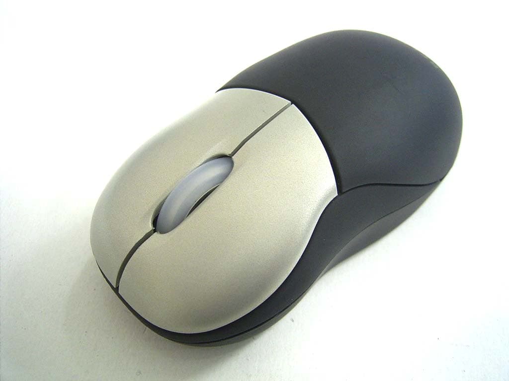
Click to zoom
Application Details
- Equipment Class
- DXX - Part 15 Low Power Communication Device Transmitter
- Date of Grant
- Mar 28, 2005
- Application Purpose
- Original Equipment
- Date of Application
- Mar 28, 2005
- Equipment Note
- MINI WIRELESS OPTICAL MOUSE
- Frequency Range
- 27.09500000 - 27.09500000
- Company
- Belkin International, Inc.
- Country
- United States
Documents & Files
Document Text
Text extracted from the exhibit documents filed with the FCC. Open a document above to read the original.
Users Manual
HARDWARE INSTALLATION 1. Make sure your computer is turned on before installing the Mouse. 2. Connect the receiver into an available USB port on your PC. (Fig. 3) Fig. 3 3. Your PC should automatically find new hardware and install necessary drivers. Note: Windows 98 SE may require you to insert your Windows 98 SE Installation CD into your computer’s CD-ROM drive to complete the install. 4. Switch on the power of the Wireless Mouse located on the backside of the Mouse. The Mouse syncs with the receiver automatically. (Fig. 4) Fig. 4 Note: If the Mouse does not sync with the receiver automatically, please see the section entitled “Synchronizing your Mouse to your Receiver”, below. Note: While traveling, please switch off the unit to save battery power. SYNCHRONIZING YOUR MOUSE TO YOUR RECEIVER If the Mouse does not automatically sync with the receiver, press the connect button on the top of the receiver. The light on the receiver will blink rapidly. Then sync the Mouse to the receiver by pushing the sync button on the bottom of the Mouse. The light on the receiver will stop blinking and light brightly. (Fig. 5) Fig. 5 INTRODUCTION Congratulations and thank you for purchasing the MiniWireless Optical Mouse from Belkin. You are about to experience a whole new world of computing convenience with superior input features and navigating accuracy. The MiniWireless Optical Mouse provides a great radio frequency (RF) wireless input solution for the mobile professional. SYSTEM REQUIREMENTS PC 486 or higher Windows ® 98 SE, Me, 2000, XP USB port CD-ROM drive PACKAGE INCLUDES MiniWireless Optical Mouse USB Receiver User Manual 2 AAA Batteries OVERVIEW Before starting the installation of the hardware for the Mouse, please remove any drivers or software from any mice that were previously installed on your computer. This is to avoid any confl icts they may create, which could result in an improper installation of your Mouse. Please consult the documents that came with your previous mouse for proper instructions on how to uninstall the software and drivers. MOUSE SETUP 1. Remove the top cover of your Mouse by pressing and holding the bottom release tab. (Fig. 1) FFig. 1ig. 1 2. Insert 2 AAA batteries. (Fig. 2) Fig. 2 2 3. Replace the top cover and close. Note: Be sure to check polarity (+ or – sign) and insert battery properly. Note: Each time you repeat this step, the Mouse randomly selects a new ID. This allows multiple wireless mice to work in the same location without cross talk. If you experience cross talk with another wireless mouse, repeat the synchronizing steps to change the channel. SETUP FOR MULTIPLE USERS When using more than one MiniWireless Optical Mouse in the same location, set up one Mouse at a time. You must complete the setup for each Mouse before beginning to set up the next Mouse. ENVIRONMENT To avoid environment interference, which will shorten the effective operation distance, please note the following: 1. Do not put the Mouse and receiver on a metal cabinet or desk. Metal creates RF interference, which may impair the RF communication and shorten the communication distance. 2. Keep a distance of more than 4.9 feet (1.5m) between your Mouse and MiniWireless Optical Mouse F8E874 P74749-A User Manual Navigate your notebook computer with optical precision and wireless freedom another operational RF device to avoid interference. 3. The optical sensor of the Mouse will not work correctly if placed on a mirror, glass, or on any reflecting or half-tone painted surface. TROUBLESHOOTING The cursor doesn’t react when I move the Mouse. 1. This is probably because the distance between the receiver and Mouse exceeds the working range of 3.3 feet (1m). Adjust so that the Mouse is closer to the receiver. 2. Make sure that the Mouse is not placed on a reflective surface such as a mirror, glass, half-tone painted surface, or on a 3-D mouse pad. When using the wireless device on a metal table or near metal furniture, use a non-reflective, thick mouse pad to reduce the potential for interference. 3. Your synchronizing setup may not have worked properly. Please repeat the synchronization setup process. Why don’t the scroll functions work with my notebook computer? Check to be sure that you have disabled your notebook computer’s trackball, touch pad, or J-Key in the Control Panel. Then enable the external port so that all your Mouse’s functions will be available. My USB Mouse was not detected by the system and won’t work. What should I do? Please do the following: 1. Ensure that your USB Mouse is completely plugged into the USB port. 2. Check the functioning of your system’s USB port in the “Device Manager” page of System Properties. If there is a circled exclamation point through the USB port’s icon, the USB controller has a problem. Please try to uninstall and then reinstall the USB driver, or contact your PC manufacturer’s technical support department. 3. Check the version of your operating system. If you are not running Windows 98 SE, Me, 2000, or XP, please update your operating system to one of these, so that the USB device can be enabled. 4. Make sure that the USB port is enabled in the BIOS setup. FCC/CE Statement DECLARATION OF CONFORMITY WITH FCC RULES FOR ELECTROMAGNETIC COMPATIBILITY We, Belkin Corporation, of 501 West Walnut Street, Compton, CA 90220, declare under our sole responsibility that the product, F8E874, to which this declaration relates, complies with Part 15 of the FCC Rules. Operation is subject to the following two conditions: (1) this device may not cause harmful interference, and (2) this device must accept any interference received, including interference that may cause undesired operation. Caution: Exposure to Radio Frequency Radiation. The radiated output power of this device is far below the FCC radio frequency exposure limits. Nevertheless, the device shall be used in such a manner that the potential for human contact during normal operation is minimized. When connecti…
Text truncated - open the document above for the full version.
Cover Letter(s)
Request for Confidentiality Federal Communications Commission Authorization and Evaluation Division Subject: Confidentiality Request regarding application for certification of FCC ID: K7SF8E874MSE Dear Madam or Sir: Pursuant to Sections 0.457 and 0.459 of the Commission’s Rules, we hereby request confidential treatment of information accompanying this application as outlined below: l Schematics l Part List l Block diagram l Operational description The above materials contain trade secrets and proprietary information not customarily released to the public. The public disclosure of these materials may be harmful to the applicant and provide unjustified benefits to its competitors. The applicant understands that pursuant to Section 0.457 of the Rules, disclosure of this application and all accompanying documentation will not be made before the date of the Grant for this application. Pursuant to DA 04-1705 June 15, 2004 of the Commission’s public notice, we also request temporary confidential treatment of information accompanying this application as outlined below: l External Photos l Internal Photos l Test Setup Photos l User’s Manual Sincerely, Mark Freeman, Product Manager Belkin Corporation
ID Label/Location Info
LABEL Format: LABEL Size: 55.4 x 33.09 mm LABEL Position: LABEL
Test Report
Test Report ----------------------------------------------------------------------------- 1/12 Report No.: B1515050120 Training Research Co., Ltd., TEL: 886-2-26461146, Fax: 886-2-26461778 Report No. B1515050120 FCC ID K7SF8E874MSE Specifications FCC Part 15, Class B Test Method ANSI C63.4 Application ■Original □Class II Changes Applicant Belkin Corporation Applicant 501 West Walnut Street Compton, address CA 90220-5221, USA Product name Mini Wireless Optical Mouse Items tested Wireless Mouse Model No. F8E874 Sample No. B15050119 EUT Condition ■Engineering sample □Pre-production □Final production Frequency 27.09536MHz Results Passed (As detailed within this report) Date 02/17/2005 (month / day / year)(Sample received) 03/15/2005 (month / day / year)(Tested) Prepared by Project Engineer Authorized by V. General Manager (Jacob Lin) Issue date March 24, 2005 (month / day / year) Modified by TRC None Tested by Training Research Co., Ltd. (Accredited by NVLAP) Office at 1F, No. 255, Nan Yang Street, Hsichih, Taipei Hsien 221, Taiwan Open site at No. 15, Lane 530, Pa-Lian RD., Sec. 1, Hsichih City, Taipei Hsien, Taiwan, R.O.C. Conditions of issue : z This test report shall not be reproduced except in full, without written approval of TRC. And the test result contained within this report only relate to the sample submitted for testing. z The test data in this test report are following the procedures in accordance with the terms of accreditation. z This test report and measurements made by TRC are traceable to the NIST only Conducted and Radiated Method (TRC is accredited by NVLAP, code No.: 200174-0). z The device has been tested is fully complied with the requirements the Directive FCC Part 15. Test Report ----------------------------------------------------------------------------- 2/12 Report No.: B1515050120 Training Research Co., Ltd., TEL: 886-2-26461146, Fax: 886-2-26461778 Contents Chapter 1 Introduction Description of EUT ................................................................................................................... 3 Configuration of Test Setup ...................................................................................................... 4 List of Support Equipment ........................................................................................................ 4 Chapter 2 Conducted Emission Test Test Condition and Setup .......................................................................................................... 5 Chapter 3 Peak Power Measurement (Frequency Band: 26.96 ~ 27.28) Test Setup .................................................................................................................................. 6 Test Procedure........................................................................................................................... 6 Chapter 4 Radiated Emission Test Test Condition and Setup .......................................................................................................... 7 Radiated Test Placement ........................................................................................................... 8 Appendix A: Peak Power and Radiated test result ......................................................................................... 9 Appendix B: Band Edge of Measurement ..................................................................................................... 11 Test Report ----------------------------------------------------------------------------- 3/12 Report No.: B1515050120 Training Research Co., Ltd., TEL: 886-2-26461146, Fax: 886-2-26461778 Chapter 1 Introduction Description of EUT: EUT : Wireless Mouse Model No. : F8E874 Product name : Mini Wireless Optical Mouse Frequency Range : 26.96 – 27.28 MHz Power Type : Powered by two 1.5VDC AAA batteries *This EUT has one channel (each with 256 IDs): 27.09536 MHz Test method: Pretest was found that the emission of operating mode is worse than standby mode. So, The final test is made at the operating mode. During the measurement, the EUT was at operating mode. The radiation pretest was found out this mode was the worst case and we only recorded this data in this report. While testing, the EUT was made to transmit continuously and adjusted at a position, which transmitted the maximum emission. The test placement as the photographs showed is the worst case emission placed. (If the emission is close to the ambient, the resolution BW and view resolution will be reduced and the data will be recorded by detection of maximum hold peak mode.) The testing configuration of test setup is showing in the next page. Test Report ----------------------------------------------------------------------------- 4/12 Report No.: B1515050120 Training Research Co., Ltd., TEL: 886-2-26461146, Fax: 886-2-26461778 Configuration of Test Setup EUT: Put two AAA size, 1.5V battery into the battery cell of EUT, powers the subject device. The EUT does not be connected with any product. List of Support Equipment Conducted (Radiated) test: N/A EUT Test Report ----------------------------------------------------------------------------- 5/12 Report No.: B1515050120 Training Research Co., Ltd., TEL: 886-2-26461146, Fax: 886-2-26461778 Chapter 2 Conducted Emission Test Test Condition and Setup: All the equipment is placed and setup according to the standard. The EUT is assembled on a wooden table that is 80 cm high, is placed 40 cm from the back-wall that is a vertical conducting plane. One LISN is for EUT, the other LISN is for support equipment. They are all placed on the conductive ground. The EUT’s LISN connect a line switch box for selecting L1 or L2, then connect to a preamplifier and Spectrum. The spectrum measured from 150KHz to 30MHz. Conducted emission levels are detected at max. peak mode. But if the max. peak mode failed or over average limit, it will be measured by QP and average detection mode using the Receiver. While testing, there is the wors…
Text truncated - open the document above for the full version.
Test Setup Photos
Radiated Test Placement: (Photographs)
Contact Information
Applicant
Jay TU(Manager, Regulatory Compliance)
Test Firm
Training Research Co., LtdJack Tsai
Technical Specifications
| # | Rule Parts | Frequency Range | Power Output |
|---|---|---|---|
| 1 | 15C | 27.095 MHz - 27.095 MHz | - |
Other Applications from Belkin International, Inc.
K7S-CAB029
Aug 11, 2026SureFind Loop Cable Tag
Equipment Class
DTS - Digital Transmission SystemK7SBPD024
Aug 10, 2026UltraCharge Pro Slim Magnetic Power Bank 5K with BoostSolid Cell
Equipment Class
DCD - Part 15 Low Power Transmitter Below 1705 kHzK7SMMA016
Jul 22, 2026SureFind Wallet Stand
Equipment Class
DTS - Digital Transmission SystemK7SMMA015
Jul 10, 2026SureFind
Equipment Class
DTS - Digital Transmission SystemK7SAUC018
Jun 17, 2026SoundForm Dot ANC Earbuds, SoundForm Dot Earbuds
Equipment Class
DTS - Digital Transmission System