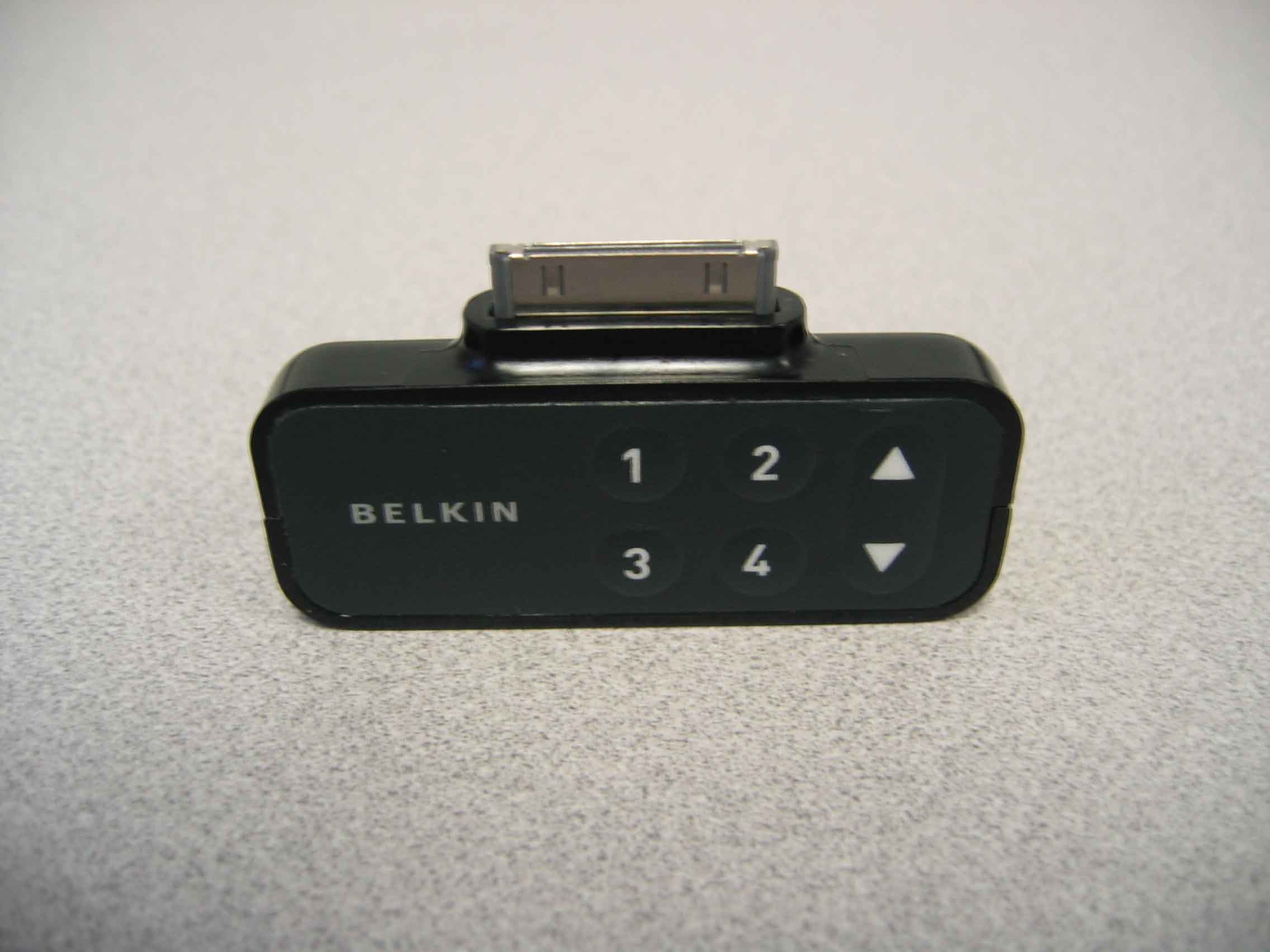
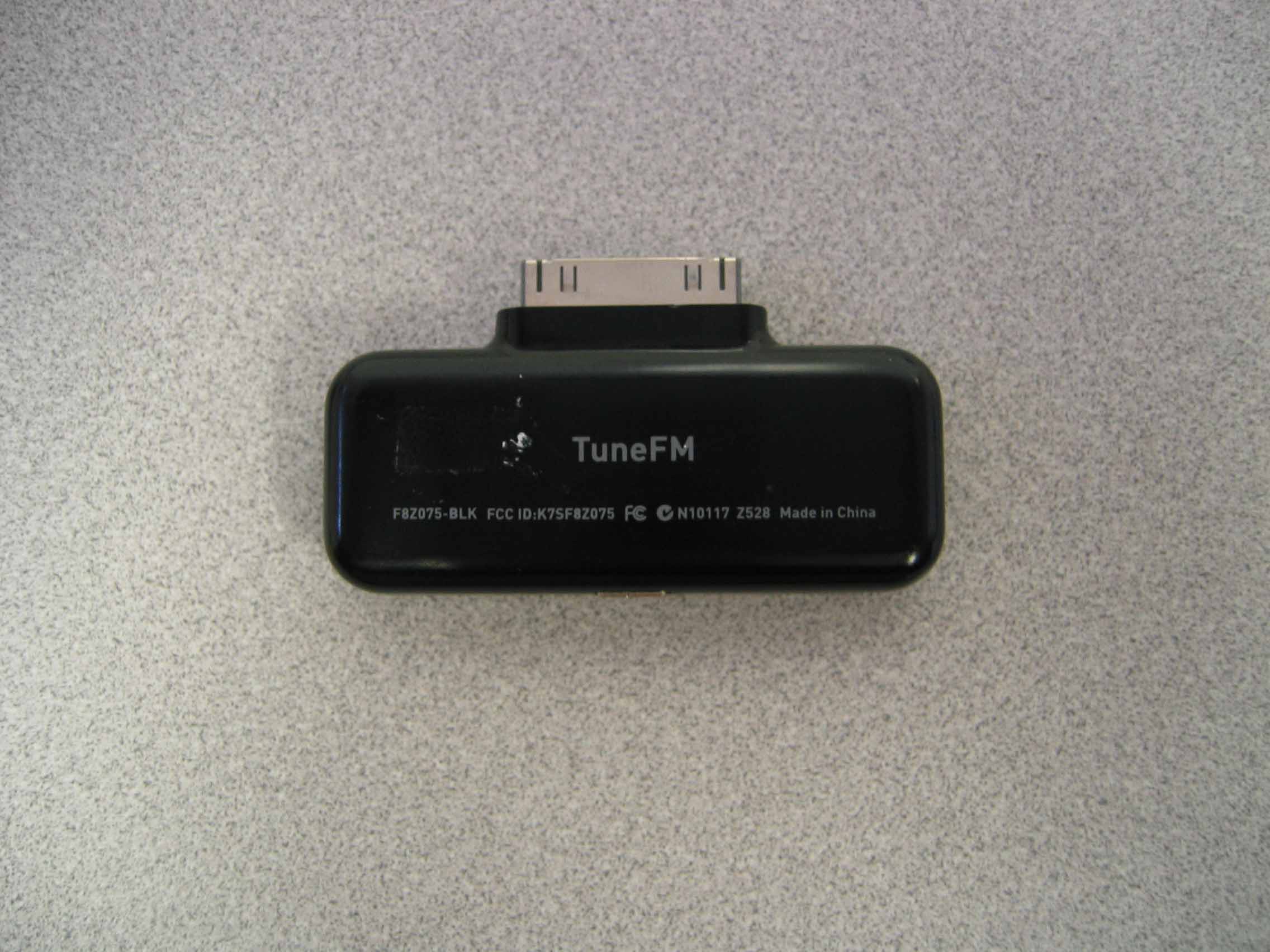
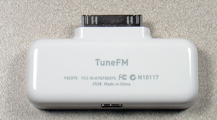
K7SF8Z075Tune FM for iPod - Model F8Z075
Belkin International, Inc.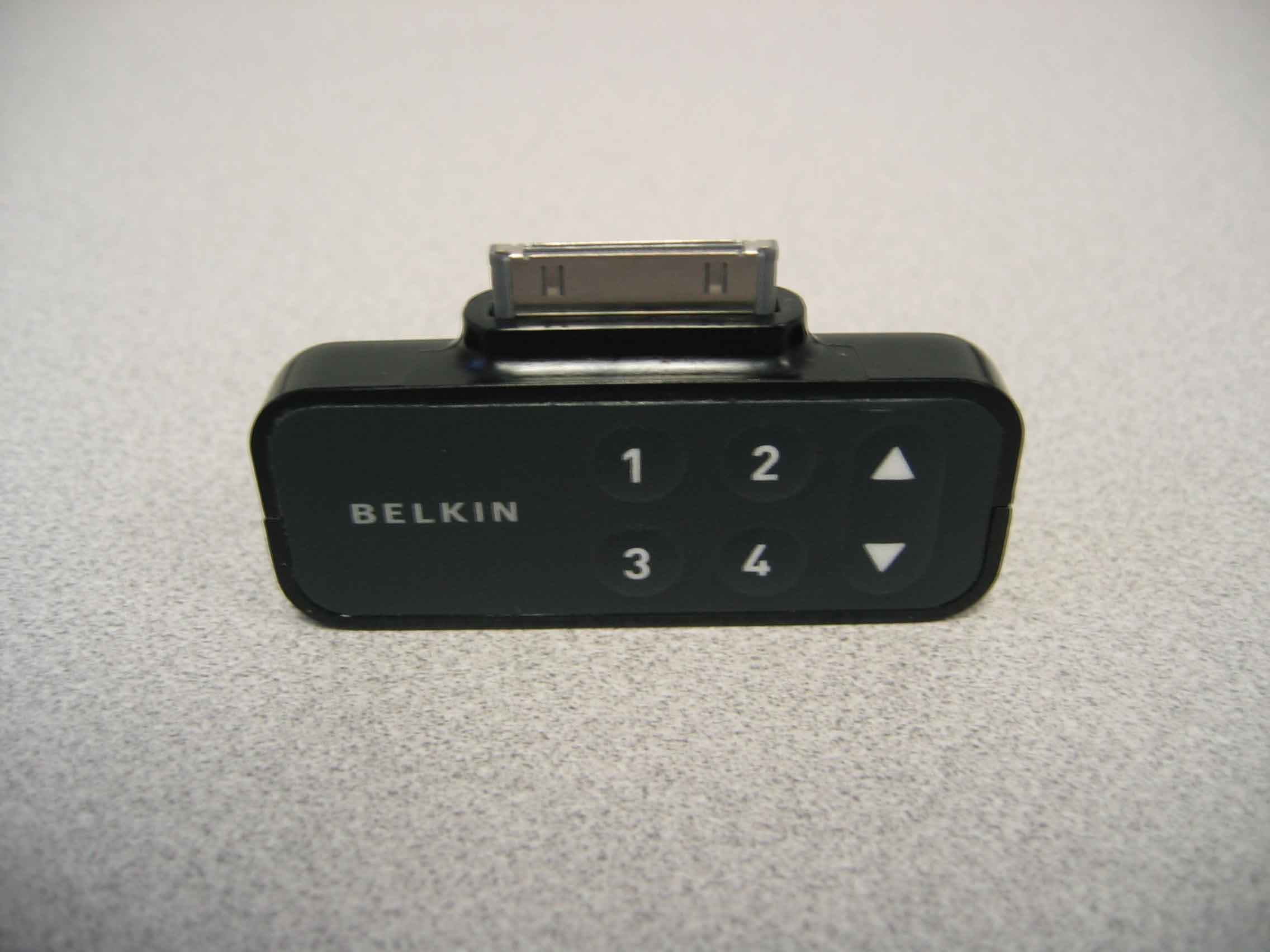
Click to zoom
Application Details
- Equipment Class
- DXT - Part 15 Low Power Transceiver, Rx Verified
- Date of Grant
- Apr 18, 2006
- Application Purpose
- Original Equipment
- Date of Application
- Apr 18, 2006
- Equipment Note
- Tune FM for iPod - Model F8Z075
- Frequency Range
- 88.10000000 - 107.90000000
- Company
- Belkin International, Inc.
- Country
- United States
Documents & Files
Document Text
Text extracted from the exhibit documents filed with the FCC. Open a document above to read the original.
Users Manual
User Manual TuneFM ™ for iPod ® Introduction Congratulations and thank you for purchasing the innovative TuneFM from Belkin. This product is designed to play your iPod through your car, home, or portable stereo. Please review this User Manual carefully so that you can be sure to get the most from your iPod, virtually anywhere you go. Package Includes: Introduction | 01 Plastic Spacer (for use only when your iPod is not in a case) TuneFM for iPod Auto Power Cord Car Setup Instructions Car Setup Instructions 1. Turn down your car stereo’s volume. 2. Connect the Belkin TuneFM to your iPod (at the bottom of the iPod). 3. Connect the included Auto Power Cord to your cigarette-lighter outlet in your car and to the bottom of your TuneFM for optional powering and charging in the car. | 02 The TuneFM transmitter function automatically turns on when the iPod is connected. It automatically turns off when the iPod is removed. 1. Tune your stereo frequency to a channel with a weak broadcast signal. The ideal channel is one that is not broadcasting a radio program, or is doing so weakly. 2. Insert the TuneFM into your iPod. The iPod backlight will turn on and the current transmitter frequency will be displayed on the iPod screen. 3. Press the ▲ or ▼ button on the TuneFM to select the transmission frequency chosen in step 1. The frequency will be visible on the iPod’s screen. Pressing and holding either button will provide faster tuning. 4. After displaying the current frequency for five seconds, the iPod screen will return to the iPod Main Menu. This happens whenever you make changes to the TuneFM’s settings. All settings—including transmission frequency, volume-control setting, and stereo/mono-control settings—are permanently stored in memory at this time. Note: iPod playback will pause momentarily when entering and exiting the TuneFM control menu. Playback will quickly resume. Using the TuneFM Transmitter Using the TuneFM Transmitter | 03 5. Adjust the volume of your FM radio to the desired listening level. NOTE: We recommend that you remove the TuneFM from the iPod when not in use. Frequency display Frequency selector Memory station display Memory stations 1 – 4 Using the TuneFM Transmitter Using the TuneFM Transmitter | 04 Plastic spacer 1. To store a preset, select the desired frequency using ▲ or ▼buttons. Press and hold the desired preset button (1, 2, 3, or 4) for two seconds. An audible beep sounds in the transmitted audio when the new frequency is programmed*. The iPod display reflects the change when the memory button is released by showing which memory button was pressed followed by the frequency saved in that memory position. *Do NOT remove the TuneFM from the iPod until it returns to the Main Menu screen or new settings may not be saved. 2. To transmit over one of your preset frequencies, momentarily press “1”, “2”, ”3”, or “4”. This will instantly tune the FM transmitter to the frequency stored in that preset. Transmission-Volume Setting Although the default volume setting will be ideal for most conditions, you may be able to improve the performance of the TuneFM by adjusting the volume of the transmitted audio signal. The TuneFM allows you to select one of five volume levels. You may wish to decrease the volume if you experience distorted audio. You can access the transmission-volume menu by pressing the “1” and “2” buttons simultaneously. TuneFM displays the current volume setting on the iPod, which is represented by “VOL 1” (low), “VOL 2”, “VOL 3” (default), “VOL 4”, and “VOL 5” (high). You can then change the volume level by using the up and down arrows. To accept your volume selection, simply wait for the iPod screen to return to the iPod Main Menu. Note: The iPod nano has a lower audio-output level than other iPod models, so a volume setting of “VOL 4” or “VOL 5” works best for iPod nano. Storing and Using Presets | 05 Storing and Using Presets ���������������������������������������������������������������������������������� ������������������������������������������������������� ������������������������� Stereo/Mono Selection Stereo/Mono Selection ���������������������������������������������������������������������������������� ������������������������������������������������������� ������������������������� ���������������������������������������������������������������������������������� ������������������������������������������������������� ������������������������� Transmitting music in stereo generally gives you the highest-quality listening experience. However, you may get better FM signal reception by changing the transmission to mono. The TuneFM transmits in stereo mode by default. We suggest that you switch from stereo to mono transmission only if your car stereo is NOT receiving a clear signal from the TuneFM, or if you are listening to mono recordings such as audio books. You can access the stereo/mono transmission menu by pressing the “1” and “3” buttons simultaneously for two seconds. The TuneFM then displays the current mode setting, which is represented by “MONO” or “ST”. You can change the mode by pressing the up or down arrows. Either arrow will change between the two modes. The new setting takes effect immediately. To accept your mode selection, simply wait for the iPod screen to return to the iPod Main Menu. | 06 Issue – The audio is distorted. Solution Tune your car stereo and the TuneFM to a different frequency. Issue – I am unable to get clear FM reception. Solution 1 Tune your car stereo and the TuneFM to a different frequency. Solution 2 In some instances, lowering the car antenna (available in some cars) improves the clarity of the TuneFM’s signal. Solution 3 Change the stereo/mono setting to mono mode. This may improve signal reception, but the audio will be monaural instead of stereo. Solution 4 If used indoors, attach or reposition the antennae on the stereo receiver. Troubleshooting | 07 Troubleshooting Issue – iPod playback stays paused after I’ve…
Text truncated - open the document above for the full version.
Cover Letter(s)
BELKI N~ 501W.WalnutStreet- Compton- California90220USA April6,2006 FederalCommunicationsCommission EquipmentApprovalServices P.O.Box358315 Pittsburgh,PA15251-5315 USA FCCID:K7SF8Z075 ToWhomIt MayConcern: Werequestunder47CFR0.459and47CFR0.457thatmaterialssubmittedtotheTelecommunications CertificationBodybewithheldfrompublicinspection.. Specifically,BelkinCorporationrequeststhatthefollowingmaterialsbewithheldfrompublicinspectionunder 47CFR0.459and47CFR0.457becausetheyareconfidentialtradesecretsandtechnicaldatawhichwouldbe guardedfromcompetitors. (1)Detailedcircuitschematicofunitundertest (2)Partslist (3)Blockdiagram Therefore,inaccordancewith47CFR0.459and47CFR0.457werequestthattheabovelistedmaterials,copies ofwhichareattachedhere,bewithheldfrompublicinspection. TacV.Pham InternationalRegulatoryComplianceManager
Cover Letter(s)
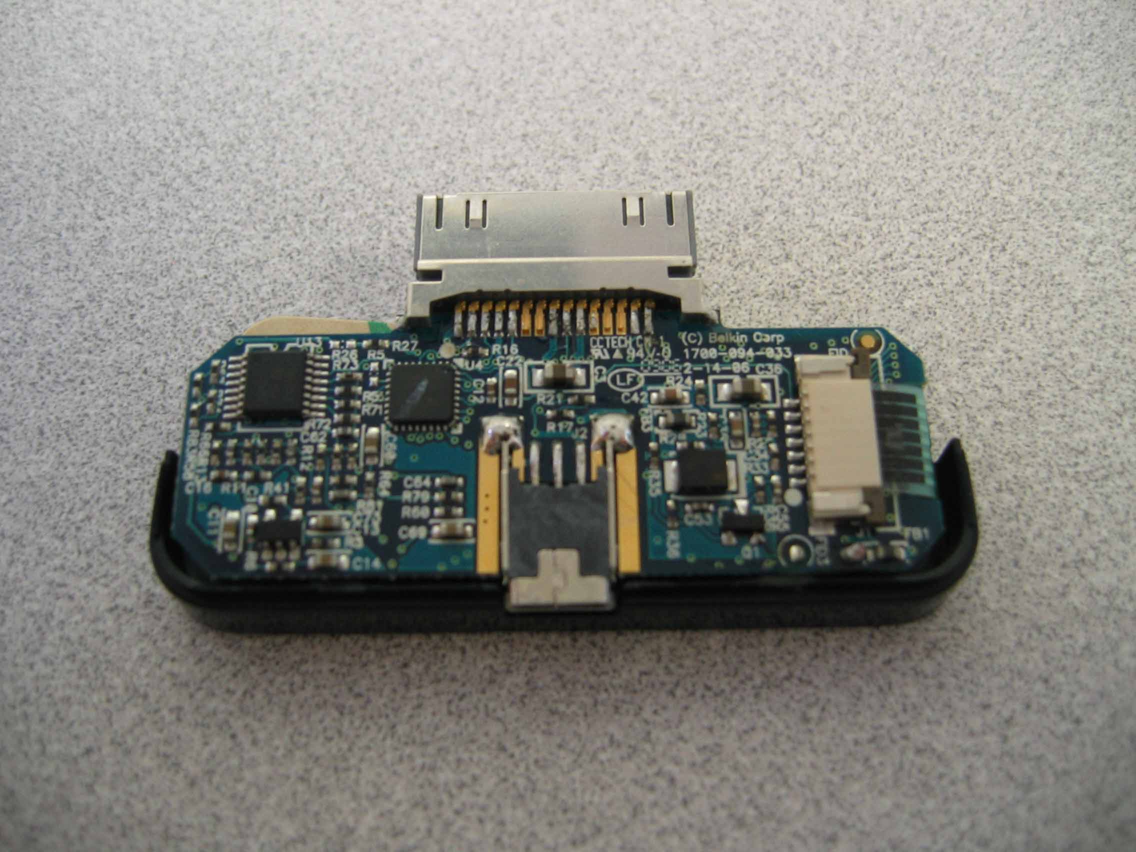
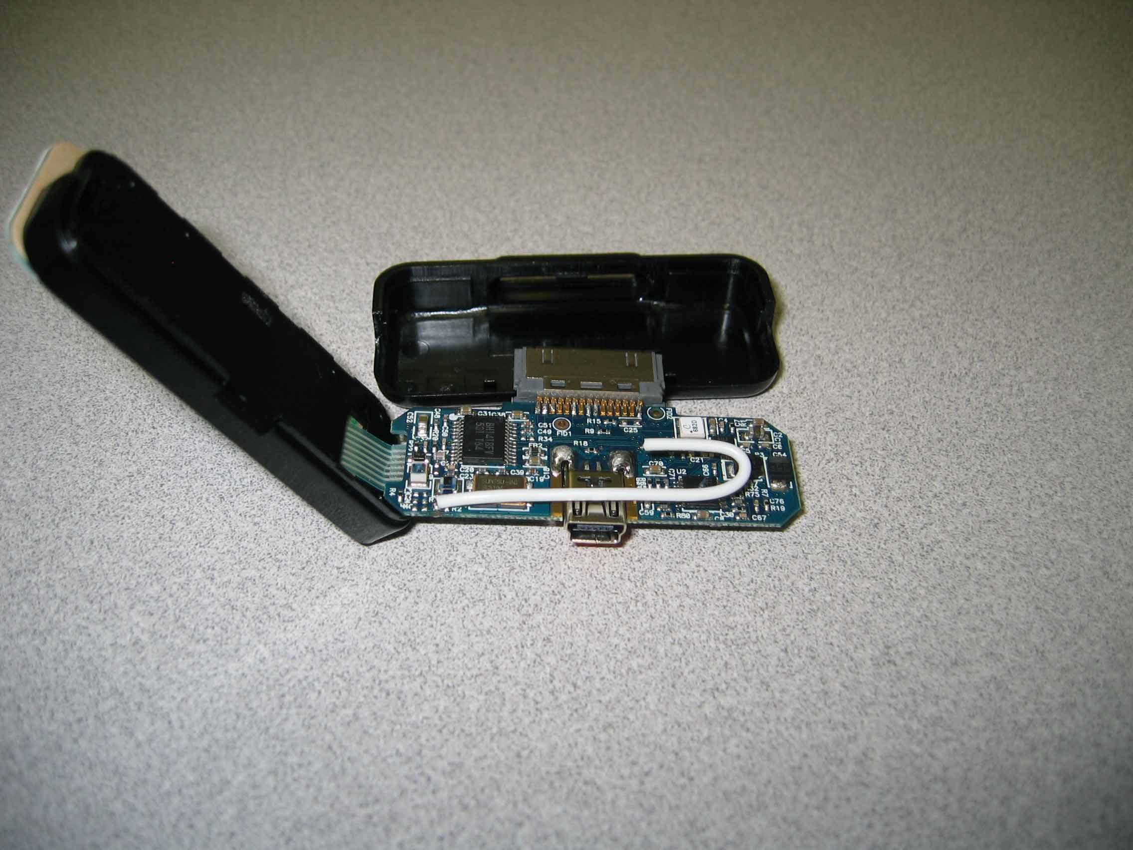
Appendix A Non-Conformities for US Radio Equipment Authorization Non-Conformities FC C ID: K7SF8Z075 (Ref # E06-000094-1) The items listed below represent requests for information following review of this application. Further question may arise pen ding review of responses to these items. OK # Non-Conformity or Co mment Submitted Response Respondent / Date of Response X 1 The test laboratory scope of accr editation only lists FCC part 15B for ITE equipment. Has the test lab requested scope extension for part 15C? If not, please provide at least two of the following items: Laboratory test procedures used for measurements performed, test laboratory personnel training records, portions of the quality manual pertaining to the testing performed. Chromerics provided info for CKC CS Assessment 4/18/06 - Chromerics X 2 Please provide additional internal pho tos showing the opposite side of the PCB in accordance with 2.1033(b)(7). Photo provided 4/10/06 - Belkin X 3 The copy of the label provided is not legible; please provide an updated sample label. Updated label provided 4/10/06 - Belkin X 4 The block diagram lists an oscillator fe ed to the RF circuitry at a frequency below 30MHz. The test report does not provide demonstration compliance of the product within this frequency rang e. Please provide demonstration of compliance to the frequency range as required by 15.33. Updated test report provided 4/18/06 - Belkin X 5 Please provide detector functions and bandwidths used for testing in accordance with 15.35. Updated test report provided 4/18/06 - Belkin X 6 Please confirm that equipment position tested was maximized using three orthogonal planes as required by ANSI C63.4 during preliminary investigation. Updated test report provided 4/18/06 - Belkin X 7 Please provide demonstration of compliance to 15.239(a) that the fundamental lies wholly within the authorized frequency band (ie band edge compliance). Updated test report provided 4/18/06 - Belkin X 8 CKC CS to ensure use of loop antenna for frequencies tested below 30MHz. Updated test report provided – Loop antenna was used. 4/18/06 - Belkin
Operational Description
501 W. Walnut Street – Compton – California 90220 USA Operation Description: The Belkin Corporation TuneFM model F8Z075 is a device that wirelessly transmits audio signals from an iPod to a FM receiver. It also allows the user to set the transmission frequency in the band 88.1MHz to 107.9MHz in 0.1MHz intervals. The TuneFM model F8Z075 is a battery powered device. It operates on 3.3Vdc supplied by the iPod. It receives both serial communication and audio signal from the iPod.
Test Report
TEST SERVICES EMC EVALUATION OF THE BELKIN CORPORATION TUNEFM - MODEL F8Z075 Date: APRIL 18, 2006 Test Report Number: TRR0296.06 REVISION 1 IN ACCORDANCE WITH FCC PART 15 SUBPART A 15.33 FCC PART 15 SUBPART C 15.209 FCC PART 15 SUBPART C 15.239 AS/NZS 4268:2003 Prepared For: BELKIN CORPORATION 1057 EAST HENRIETTA ROAD ROCHESTER, NEW YORK 14623 ATTENTION: JEFF MEYERS Prepared By: MATTHEW HANEL CHOMERICS TEST SERVICES ROCHESTER FACILITY 100 INDIGO CREEK DRIVE ROCHESTER, NEW YORK 14626 WOBURN FACILITY 77 DRAGON COURT WOBURN, MASSACHUSETTS 01801 This report shall not be reproduced except in full without the written approval of Chomerics Test Services. TEST SERVICES Belkin Corporation TuneFM - Model F8Z075 Document #: TRR0296.06 Rev. 1 Date: April 18, 2006 Page 2 of 46 TABLE OF CONTENTS 1.0 General 1.1 Introduction 1.1.1 Purpose 1.1.2 Requirements 1.2 Test Summary 1.2.1 Summary of Recommendations 1.3 Administrative Data 1.3.1 Test Facility 1.3.2 Equipment Calibration 1.3.3 Test Personnel 1.4 Test Set-up 1.4.1 Test Site Matrix 1.4.2 Test Site Descriptions 1.4.3 Equipment Under Test 1.4.4 Block Diagram 2.0 Emissions Tests Performed 2.1 20dB Fundamental Emission 2.1.1 Equipment Used 2.1.2 Test Conditions 2.1.3 Test Method 2.1.4 Results 2.1.5 Test data 2.1.6 Photographic Documentation 2.2 FCC Part 15 Subpart C Field Strength (FCC 47 CFR 15.239) 2.2.1 Equipment Used 2.2.2 Test Conditions 2.2.3 Test Method 2.2.4 Results 2.2.5 Test Data 2.2.6 Photographic Documentation 2.3 FCC Class B Subpart C Radiated Emissions (FCC 47 CFR 15.209 Class B) 2.3.1 Equipment Used 2.3.2 Test Conditions 2.3.3 Test Method 2.3.4 Result 2.3.5 Test Data 2.3.6 Photographic Documentation TEST SERVICES Belkin Corporation TuneFM - Model F8Z075 Document #: TRR0296.06 Rev. 1 Date: April 18, 2006 Page 3 of 46 TABLE OF CONTENTS (continued) 2.4 Effective Isotropic Radiated Power 2.4.1 Equipment Used 2.4.2 Test Conditions 2.4.3 Test Method 2.4.4 Result 2.4.5 Test Data 2.4.6 Photographic Documentation 2.5 FCC Class B Subpart A Radiated Emissions (FCC 47 CFR 15.33) 2.5.1 Equipment Used 2.5.2 Test Conditions 2.5.3 Test Method 2.5.4 Results 2.5.5 Test Data 2.5.6 Photographic Documentation Appendix A: Test Log TEST SERVICES Belkin Corporation TuneFM - Model F8Z075 Document #: TRR0296.06 Rev. 1 Date: April 18, 2006 Page 4 of 46 LIST OF DEFINITIONS/ABBREVIATIONS AC Alternating Current BB Broadband BW Bandwidth cm Centimeter CPU Calibrate Prior to Use dB Decibel DC Direct Current EMC Electromagnetic Compatibility EMI Electromagnetic Interference ER Electric Radiation EUT Equipment Under Test GHz GigaHertz Hz Hertz I-face Interface kHz KiloHertz m Meter MHz MegaHertz mm Millimeter mS Millisecond mV MilliVolt MR Magnetic Radiation NB Narrowband NCR No Calibration Required PLC Power Line Conduction PPS Pulses Per Second uF MicroFarad uH MicroHenry uS Microsecond uV MicroVolt UWC Use With Calibrated Equipment TEST SERVICES Belkin Corporation TuneFM - Model F8Z075 Document #: TRR0296.06 Rev. 1 Date: April 18, 2006 Page 5 of 46 1.0 GENERAL 1.1 Introduction 1.1.1 Purpose The purpose of this report is to document the performance of the Belkin Corporation TuneFM - Model F8Z075 during an electromagnetic interference (EMI) test and record the test requirements and procedures used. At the request of Belkin Corporation, the tests were performed by Chomerics Test Services (CTS) of Woburn, Massachusetts at Chomerics’ test facility located in Rochester, New York. The assessment will determine the compliance or non-compliance with the requirements set up by the FCC Part 15 Subpart C 15.239 and AS/NZS 4268:2003 Radio Equipment and Systems – Short Range Devices- Limits and Methods measurement. Jeff Meyers from Belkin Corporation was present during testing. Testing was performed during the period of March 21 – 22, and April 14, 2006 under Chomerics’ order number 941372. 1.1.2 Requirements The requirements for the sequence of tests performed on the TuneFM - Model F8Z075 are as follows: FCC Part 15 Subpart C 15.239 – Section 2.0 FCC Part 15 Subpart C 15.239, Emission requirements: Sec. 15.239: Operation in the band 88-108 MHz. - Emissions from the intentional radiator shall be confined within a band 200 kHz wide centered on the operating frequency. The 200 kHz band shall lie wholly within the frequency range of 88-108 MHz. The field strength of any emissions within the permitted 200 kHz band shall not exceed 250 microVolts/meter (47.95 dBuV) at 3 meters. The emission limit in this paragraph is based on measurement instrumentation employing an average detector. The provisions for limiting Peak emissions in 15.35 apply The field strength of any emissions radiated on any frequency outside of the specified 200 kHz band shall not exceed the general radiated emission limits in Sec. 15.209. AS/NZS 4268:2003 – Section 2.4 Table 1 Maximum EIRP = 10uW Maximum Transmitter Spurious Emissions EIRP = 0.1uW Maximum 20dB Bandwidth 180kHz TEST SERVICES Belkin Corporation TuneFM - Model F8Z075 Document #: TRR0296.06 Rev. 1 Date: April 18, 2006 Page 6 of 46 FCC Part 15 Subpart C 15.33 – Section 2.5 FCC Part 15 Subpart C 15.33, Radio Frequency Devices: For an intentional radiator, the spectrum shall be investigated from the lowest radio frequency signal generated in the device, without going below 9 kHz, up to at least the frequency shown in paragraph (1). (1) If the intentional radiator operates below 10 GHz: to the tenth harmonic of the highest fundamental or to 40 GHz, whichever is lower. FCC Part 15 Subpart A 15.35 FCC Part 15 Subpart C 15.35, Measurement Detector Functions and Bandwidths: (a) On any frequency or frequencies below or equal to 1000 MHz, the limits shown are based on measuring equipment employing a CISPR quasi-peak detector function and related measurement bandwidths, unless otherwise specified. The specifications for the measuring instrument used were in accordance with CISPR 16. Peak detector measured data may be substituted for the appropriate detector data to …
Text truncated - open the document above for the full version.
Contact Information
Applicant
Jay TU(Manager, Regulatory Compliance)
Technical Contact
Belkin CorporationTac Pham
310-604-2448
501 W. Walnut Street · Compton, California · United States
Test Firm
Ortho Clinical Diagnostics EMC LabMark Stefanik
Technical Specifications
| # | Rule Parts | Frequency Range | Power Output |
|---|---|---|---|
| 1 | 15C | 88.1 MHz - 107.9 MHz | - |
Other Applications from Belkin International, Inc.
K7S-CAB029
Aug 11, 2026SureFind Loop Cable Tag
Equipment Class
DTS - Digital Transmission SystemK7SBPD024
Aug 10, 2026UltraCharge Pro Slim Magnetic Power Bank 5K with BoostSolid Cell
Equipment Class
DCD - Part 15 Low Power Transmitter Below 1705 kHzK7SMMA016
Jul 22, 2026SureFind Wallet Stand
Equipment Class
DTS - Digital Transmission SystemK7SMMA015
Jul 10, 2026SureFind
Equipment Class
DTS - Digital Transmission SystemK7SAUC018
Jun 17, 2026SoundForm Dot ANC Earbuds, SoundForm Dot Earbuds
Equipment Class
DTS - Digital Transmission System