K7SWIC008BoostCharge Pro Wireless Car Charger With MagSafe 15W
Belkin International, Inc.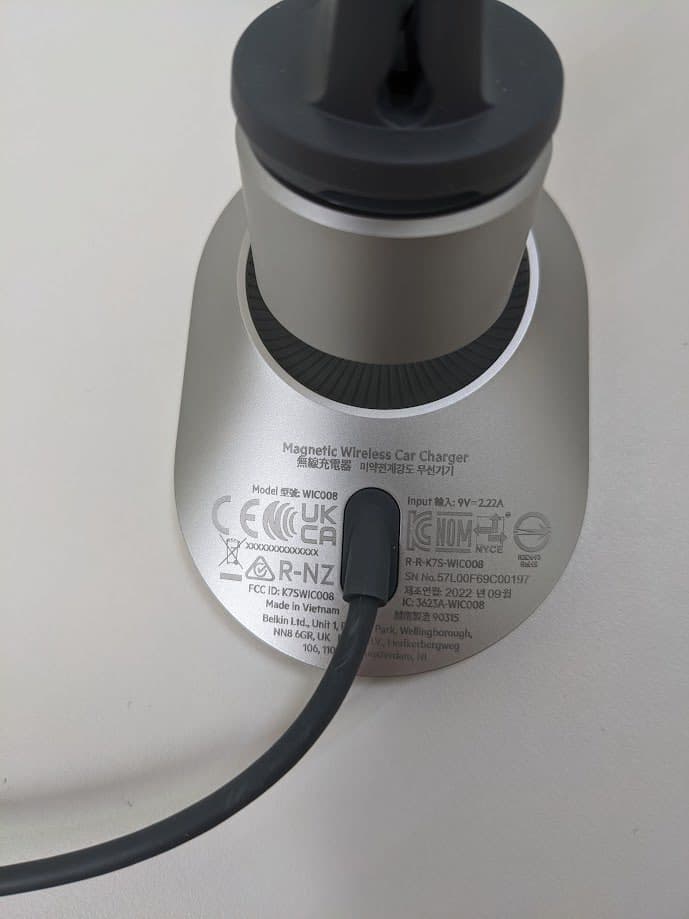
Click to zoom
Application Details
- Equipment Class
- DCD - Part 15 Low Power Transmitter Below 1705 kHz
- Date of Grant
- Nov 09, 2022
- Application Purpose
- Original Equipment
- Date of Application
- Oct 31, 2022
- Equipment Note
- BoostCharge Pro Wireless Car Charger With MagSafe 15W
- Frequency Range
- 0.12770000 - 0.12770000
- Company
- Belkin International, Inc.
- Country
- United States
Documents & Files
Document Text
Text extracted from the exhibit documents filed with the FCC. Open a document above to read the original.
Users Manual
Recycling programs for this packaging may not exist in your area. Il est possible qu’aucun programme de recyclage ne soit disponible dans votre région. Raccolta differenziata. Verifica le disposizioni del tuo Comune. Regulatory and Sustainability Information NORTH AMERICA Safety Instructions WARNING: Failure to follow these instructions could result in fire, electric shock, injury, or damage to the user, product, or other property. 1. Connect the power supply of the wireless charger into a power outlet that is close by and is easy to disconnect from the source. 2. Use indoors and in a dry location only; Avoid charging near sources of heat and humidity. 3. Keep the wireless charger and power supply away from any liquids or moisture. 4. Unplug the wireless charger when not in use for long periods of time. 5. Do not store your device in very hot or very cold locations. It is recommended to use your device at room temperature. 6. Do not use if visible defects are observed on the wireless charger or power supply. 7. Do not attempt to service, modify, or disassemble the wireless charger or power supply. 8. Use of a power supply not recommended or sold by Belkin may result in an increased risk of fire, electric shock, injury, or damage to the user, product, or other property. 9. Wireless charging power transmission rate is regulated by the wireless charging device receiving power which can be influenced by factors like, but not limited to, proprietary charging protocols, ambient temperature, current battery percentage level and age of the device being charged. CAUTION: If you experience problems with the wireless charger, please discontinue use, unplug the power supply from the socket, and contact Belkin for assistance. The marking information is located on the bottom of the apparatus. FCC Statement DECLARATION OF CONFORMITY WITH FCC RULES FOR ELECTROMAGNETIC COMPATIBILITY We, Belkin International, Inc. El Segundo, CA 90245, USA, Tel: +1(310) 751 5100, declare under our sole responsibility that this product complies with Part 15 of the FCC Rules. Operation is subject to the following two conditions: (1) this device may not cause harmful interference, and (2) this device must accept any interference received, including interference that may cause undesired operation. Federal Communications Commission Interference Statement This equipment has been tested and found to comply with the limits for a Class B digital device, pursuant to Part 15 of the FCC Rules. These limits are designed to provide reasonable protection against harmful interference in a residential installation. This equipment generates, uses, and can radiate radio frequency energy, and if not installed and used in accordance with the instructions, may cause harmful interference to radio communications. However, there is no guarantee that interference will not occur in a particular installation. If this equipment does cause harmful interference to radio or television reception, which can be determined by turning the equipment off and on, the user is encouraged to try and correct the interference by one or more of the following measures: • Reorient or relocate the receiving antenna. • Increase the distance between the equipment and the receiver. • Connect the equipment to an outlet on a circuit different from that to which the receiver is connected. • Consult the dealer or an experienced radio/TV technician for help. FCC Caution: Any changes or modifications not expressly approved by the party responsible for compliance could void the user’s authority to operate this equipment. Radiation Exposure Statement: This equipment complies with FCC radiation exposure limits set forth for an uncontrolled environment. This equipment should be installed and operated with a minimum distance of 20 cm between the radiator and your body. Innovation, Science, and Economic Development Canada Statement (ISED): This device contains licence-exempt transmitter(s)/receiver(s) that comply with Innovation, Science and Economic Development Canada’s licence-exempt RSS(s). Operation is subject to the following two conditions: (1) This device may not cause interference. (2) This device must accept any interference, including interference that may cause undesired operation of the device. Radiation Exposure Statement: This equipment complies with ISED radiation exposure limits set forth for an uncontrolled environment. This equipment should be installed and operated with a minimum distance of 20 cm between the radiator and your body. Innovation, Science and Economic Development Canada Statement: This digital apparatus complies with CAN ICES-003(B) / NMB-003(B). FRANÇAIS Informations relatives à la règlementation et à la durabilité AMÉRIQUE DU NORDZ Consignes de sécurité supplémentaires MISE EN GARDE : Le non-respect de ces instructions peut provoquer un incendie, une électrocution ou des blessures, ou endommager l’utilisateur, le produit ou d’autres biens 1. Connecter l’alimentation du chargeur sans fil à une prise secteur proche de la source et facile à déconnecter de celle-ci. 2. Utiliser ce produit à l’intérieur et dans un endroit sec uniquement; éviter de charger votre appareil près des sources de chaleur et d’humidité. 3. Garder le chargeur sans fil et l’alimentation à l’abri de tout liquide ou de l’humidité. 4. Débrancher le chargeur sans fil quand vous ne l’utilisez pas pendant de longues périodes. 5. Ne pas stocker votre appareil dans un endroit très chaud ou très froid. Il est recommandé d’utiliser votre appareil à température ambiante. 6. Si vous remarquez des défauts visibles sur le chargeur sans fil ou l’alimentation, ne pas les utiliser. 7. Ne pas tenter de réparer, modifier ou démonter le chargeur sans fil ou l’alimentation. 8. L’utilisation d’une alimentation non recommandée ou non vendue par Belkin peut augmenter le risque d’incendie, d’électrocution, de blessure ou d’endommagement de l’utilisateur, du produit ou d’autres biens. 9. La vitesse de trans…
Text truncated - open the document above for the full version.
Cover Letter(s)
Date: 10/3/2022 UL Verification Services Inc. 47173 Benicia Street Fremont, CA 94538, USA To whom it may concern: I, the undersigned, hereby authorize UL Verification Services Inc. to act on our behalf in all manners relating to application for equipment authorization, including signing of all documents relating to these matters. Any and all acts carried out by UL Verification Services Inc. on our behalf shall have the same effect as acts of our own. I, the undersigned, hereby certify that we are not subject to a denial of federal benefits, that includes FCC benefits, pursuant to Section 5301 of the Anti-Drug Abuse Act of 1988, 21 U.S.C. 853(a). In authorizing UL Verification Services Inc. as our representative, we still recognize that we are responsible to: a) fulfill the requirements for the scope of certification requested, including implementing any appropriate changes requested by UL Verification Services Telecommunications Certification Body (TCB) and / or the FCC; b) supply any and all information needed for the evaluation of the products for which certification is sought; c) make claims regarding certification only in respect of the scope for which certification has been granted; d) not use our product certification in such a manner as to bring the TCB or FCC into disrepute and to not make any statement regarding product certification which the TCB or FCC may consider misleading or unauthorized; e) discontinue use of all advertising matter that contains any reference thereto and complies with any and all actions required by the FCC upon suspension or cancellation of certification; f) use certification only to indicate that products are certified in conformity with specified standards; g) endeavor to ensure that no certificate or report or any part thereof is used in a misleading manner, and any copies of the grants/certificates shall be reproduced in their entirety; h) comply with the requirements of the TCB and FCC, including the use of marks and label information prescribed for the scope of certification, when making reference to product certification in communication media such as documents, brochure or advertisements; i) comply with the requirements for certification, supply any information needed for evaluation of products to be certified and, where applicable, make provision for the participation of observers; j) ensure that products marketed under the scope of the requested certification continue to comply with the certification requirements; k) provide a sample of a production unit for testing within 30 days of the request should this product be selected as part of either the TCB’s or the FCC’s market surveillance requirements; l) keep a record of all complaints relating to product’s compliance with requirements of relevant standard; make records available to UL or FCC when requested; take appropriate action with respect to such complaints and any deficiencies found in the product that affect compliance with requirements for certification; document the actions taken with respect to complaints and/or deficiencies; m) inform the TCB immediately of any changes that may affect its ability to comply with the certification requirements. This authorization is valid until further written notice from the applicant. Sincerely Yours, Zack Vogel Regulatory Compliance Engineer Belkin International, Inc.
Cover Letter(s)
Date: 10/3/2022 Attn: FCC Office of Engineering and Technology / UL Verification Services TCB Subject: Request for Confidentiality FCC ID: K7SWIC008 To Whom It May Concern: Pursuant to the provisions of Sections 0.457 and 0.459 of the Commission’s rules (47 CFR §§ 0.457, 0.459), we are requesting the Commission to withhold the following attachments as confidential document from public disclosure indefinitely. • Schematic Diagram • Block Diagram • Theory of Operation • Antenna Specification Above mentioned document contains detailed system and equipment description are considered as proprietary information in operation of the equipment. The public disclosure of above documents might be harmful to our company and would give competitor an unfair advantage in the market. In additional to above mentioned documents, pursuant to Public Notice DA 04-1705 of the Commission’s policy, in order to comply with the marketing regulations in 47 CFR §2.803 and the importation rules in 47 CFR §2.1204, while ensuring that business sensitive information remains confidential until the actual marketing of newly authorized devices. We are requesting the commission to grant short-term confidentiality request on the following attachments until 180 days have passed after the grant has been published and released. • External Photos • Internal Photos • Test Setup Photos • User Manual It is our understanding that all measurement test reports, FCC ID label format and correspondent during certification review process cannot be granted as confidential documents and those information will be available for public review once the grant of equipment authorization is issued. Best Regards, Zack Vogel Regulatory Compliance Engineer Belkin International, Inc.
Cover Letter(s)
Power of Attorney Date: October 6, 2022 To whom it may concern: I, the undersigned, Jay Tu, hereby authorize the person(s) listed below to act on behalf of me to sign all related documents for Belkin International, Inc.’s FCC/IC application. Name: Zack Vogel / Regulatory Compliance Engineer, Regulatory Compliance Tel: +1 800-223-5546 E-mail: [email protected] Name: Rossi Wu / Senior Regulatory Compliance Engineer, Regulatory Compliance Tel: +1 310 633 9309 # 2960 E-mail: [email protected] Name: Daisy Dai / Regulatory Compliance Engineer, Regulatory Compliance Tel: O +86 755 2387 1039 E-mail: [email protected] Respectfully, Applicant’s company name: Belkin International, Inc. Applicant’s company address: 12045 East Waterfront Dr., Playa Vista, CA 90094, United Sates Signature Name and Job Title: Jay Tu / Manager, Regulatory Compliance E-mail: [email protected] Tel: +1 310 633 9309 # 9142
Internal Photos
Component Placement – Top View C223 Coil Antenna (MagSafe iPhones – 360 kHz) – Top View C223 Coil Antenna (MagSafe iPhones – 360 kHz) – Bottom View C223 PCB (MagSafe iPhones – 360 kHz) – Top View C223 PCB (MagSafe iPhones – 360 kHz) – Bottom View
RF Exposure Info
TEST REPORT Report Number. : 14497921-E2V1 Applicant : BELKIN INTERNATIONAL, INC. 555 S. AVIATION BLVD., SUITE 180 EL SEGUNDO, CA 90245, USA Model : WIC008 FCC ID : K7SWIC008 EUT Description : BoostCharge™ Pro Wireless Car Charger With MagSafe 15W Test Standard(s) : FCC PART 1 SUBPART I FCC PART 2 SUBPART J Date Of Issue: 2022-10-03 Prepared by: UL Verification Services Inc. 47173 Benicia Street Fremont, CA 94538 U.S.A. TEL: (510) 319-4000 FAX: (510) 661-0888 REPORT NO: 14497921-E2V1 DATE: 2022-10-03 FCC ID: K7SWIC008 MODEL NUMBER: WIC008 Page 2 of 15 UL VERIFICATION SERVICES INC. FORM NO: CCSUP4701I 47173 BENICIA STREET, FREMONT, CA 94538, USA TEL: (510) 319-4000 FAX: (510) 661-0888 This report shall not be reproduced except in full, without the written approval of . UL Verification Services Inc. Revision History Rev. Issue Date Revisions Revised By V1 2022-10-03 Initial Issue --- REPORT NO: 14497921-E2V1 DATE: 2022-10-03 FCC ID: K7SWIC008 MODEL NUMBER: WIC008 Page 3 of 15 UL VERIFICATION SERVICES INC. FORM NO: CCSUP4701I 47173 BENICIA STREET, FREMONT, CA 94538, USA TEL: (510) 319-4000 FAX: (510) 661-0888 This report shall not be reproduced except in full, without the written approval of . UL Verification Services Inc. TABLE OF CONTENTS 1. ATTESTATION OF TEST RESULTS ................................................................................. 4 2. TEST METHODOLOGY ..................................................................................................... 6 3. FACILITIES AND ACCREDITATION ................................................................................. 6 4. DECISION RULES AND MEASUREMENT UNCERTAINTY .............................................. 7 4.1. METROLOGICAL TRACEABILITY .............................................................................. 7 4.2. DECISION RULES ....................................................................................................... 7 4.3. MEASUREMENT UNCERTAINTY ............................................................................... 7 5. KDB 680106 D01 SECTION 5b EQUIPMENT APPROVAL CONSIDERATIONS .............. 8 6. EQUIPMENT UNDER TEST ............................................................................................... 9 6.1. DESCRIPTION OF EUT .............................................................................................. 9 6.2. WORST-CASE CONFIGURATION AND MODE .......................................................... 9 7. TEST AND MEASUREMENT EQUIPMENT ......................................................................10 8. DUTY CYCLE ....................................................................................................................11 9. MAXIMUM PERMISSIBLE RF EXPOSURE ......................................................................12 9.1. FCC LIMITS AND SUMMARY ....................................................................................12 9.1.1. MAXIMUM RESULT SUMMARY .........................................................................13 9.1.2. E- FIELD AND H- FIELD MEASUREMENTS .......................................................13 10. RF EXPOSURE TEST SETUP AND SETUP PHOTO ....................................................15 REPORT NO: 14497921-E2V1 DATE: 2022-10-03 FCC ID: K7SWIC008 MODEL NUMBER: WIC008 Page 4 of 15 UL VERIFICATION SERVICES INC. FORM NO: CCSUP4701I 47173 BENICIA STREET, FREMONT, CA 94538, USA TEL: (510) 319-4000 FAX: (510) 661-0888 This report shall not be reproduced except in full, without the written approval of . UL Verification Services Inc. 1. ATTESTATION OF TEST RESULTS COMPANY NAME: BELKIN INTERNATIONAL, INC. 555 S. AVIATION BLVD., SUITE 180 EL SEGUNDO, CA 90245, USA EUT DESCRIPTION: BoostCharge™ Pro Wireless Car Charger With MagSafe 15W MODEL NUMBER: WIC008 SERIAL NUMBER: 57L00F69C00168 DATE TESTED: 2022-09-20 TO 2022-09-23 APPLICABLE STANDARDS STANDARD TEST RESULTS FCC PART 1 SUBPART I & PART 2 SUBPART J Complies UL Verification Services Inc. tested the above equipment in accordance with the requirements set forth in the above standards. The test results show that the equipment tested is capable of demonstrating compliance with the requirements as documented in this report. The results documented in this report apply only to the tested sample, under the conditions and modes of operation as described herein. It is the manufacturer's responsibility to assure that additional production units of this model are manufactured with identical electrical and mechanical components. All samples tested were in good operating condition throughout the entire test program. Measurement Uncertainties are published for informational purposes only and were not taken into account unless noted otherwise. This document may not be altered or revised in any way unless done so by UL Verification Services Inc. and all revisions are duly noted in the revisions section. Any alteration of this document not carried out by UL Verification Services Inc. will constitute fraud and shall nullify the document. This report must not be used by the client to claim product certification, approval, or endorsement by A2LA, NIST, any agency of the Federal Government, or any agency of the U.S. government. REPORT NO: 14497921-E2V1 DATE: 2022-10-03 FCC ID: K7SWIC008 MODEL NUMBER: WIC008 Page 5 of 15 UL VERIFICATION SERVICES INC. FORM NO: CCSUP4701I 47173 BENICIA STREET, FREMONT, CA 94538, USA TEL: (510) 319-4000 FAX: (510) 661-0888 This report shall not be reproduced except in full, without the written approval of . UL Verification Services Inc. Approved & Released For UL Verification Services Inc. By: Prepared By: Francisco de Anda Tom Chen Staff Engineer Senior Test Engineer Consumer Technology Division Consumer Technology Division UL Verification Services Inc. UL Verification Services Inc. Reviewed By: Tina Chu Senior Project Engineer Consumer Technology Division UL Verification Services Inc. REPORT NO: 14497921-E2V1 DATE: 2022-10-03 FCC ID:…
Text truncated - open the document above for the full version.
RF Exposure Info
Project Details Project request id : 2022-10-17_12_55_Belkin Project Name : BoostCharge™ Pro Wireless Car Charger With MagSafe 15W Project Creation Date : 18 Oct 2022 Name of the customer : Belkin International, Inc. Executive Summary Project Name:BoostCharge™ Pro Wireless Car Charger With MagSafe 15W Name of the customer:Belkin International, Inc. Equipment Under Test (EUT) Model Name:WIC008 Puck type:MFI618-00021 Receipt Date:18 Oct 2022 Test Date:19 Oct 2022 Issue Date:19 Oct 2022 FCC ID:K7SWIC008 Conclusions: PASS The sample of the above-mentioned product in accordance with the provisions of the relevant specific standards and directives. Description: The EUT, BoostCharge™ Pro Wireless Car Charger With MagSafe 15W, is a single charging coil capable of charging one client device at a time. The coil is used for charging a MagSafe iPhone at 360kHz (15W). The EUT is intended to be mounted to a vehicle’s air conditioning vent and intended to only be used hands-free. When installed and mounted in the vehicle, it will never be used near any portion of the head or body This report details the results of the simulation carried out on mentioned EUT. The results contained in this report do not relate to other other models/designs of the same product. SAR Compliance Simulation Report for WPT Charger Vendor Name: Belkin International, Inc. Model:WIC008 FCC ID: K7SWIC008 Date of Simulation: 19 Oct 2022 - 20 Oct 2022 Location: California, USA Table of Contents 1 A Brief Summary of Assessment Results 2 Introduction 3 EUT Description 4 Wireless Power Transfer System 5 SAR Simulations Methodology 6 Model Validation Methodology 7 SAR Simulations 8 Summary 9 Annex A: SAR Computational Modelling 10 Annex B: Human Tissue Modeling 11 Annex C: Simulation Model Validation 12 References List of Figures 1. Spatial 1-gram average SAR for worst-case normal use case 2. Spatial 1-gram average SAR for the worst-case unrealistic case 3. Peak values for E-field spatial distribution inside phantom for the worst-case unrealistic case 4. IEEE P1528.4 SAR Computation 5. Steps to verify Apple Simulation Model 6. Baseline setup for exposure cases 000 and 505 7. E/H-field plotting planes for two baseline simulation models. 8. H-field on the two planes for case 000 from Apple’s simulation model 9. H-field on the two planes for case 000 from MagSafe simulation model. 10. E-field on the two planes for case 000 from Apple’s simulation model 11. E-field on the two planes for case 000 from MagSafe simulation model. 12. H-field on the two planes for case 505 from Apple’s simulation model 13. H-field on the two planes for case 505 from MagSafe simulation model. 14. E-field on the two planes for case 505 from Apple’s simulation model 15. E-field on the two planes for case 505 from MagSafe simulation model. List of Tables 1. Summary of evaluated cases for SAR and E field compliance. 2. Key design parameters. 3. Material Properties of the additional housing geometries 4. Material Assignments for the additional housing geometries 5. Simulation results for evaluated normal use cases for 1-gram averaged SAR and maximum averaged internal E-field. 6. Simulation results for unrealistic direct exposure cases for 1-gram averaged SAR and maximum averaged internal E- field 7. Electrical properties for body & hand layers 1. A Brief Summary of Assessment Results The wireless power transfer (WPT) device is designed to charge Apple phone through closely coupled inductive field at 360 kHz. The evaluation of the SAR and E-field induced inside the phantom is the main purpose of this report. The results for different scenarios where the charger and the phone are held in different positions relative to each other and relative to the phantom, is summarized in the Table, below. Table 1. Summary of evaluated cases for SAR and E field compliance. Cells marked in "GREEN" values are within limit. Cells marked in "RED" values are out of limit. For the normal use cases (cases 1-4 in Table 1), the highest 1g averaged SAR of 1.1e-05 W/kg occurs when there is maximum offset with phantom on the charger side, and the highest peak spatial average E-field of 0.399 V/m occurs for maximum offset with phantom on the phone side. For the unrealistic (theoretical) cases (cases 5-6 in Table 1), the highest 1g averaged SAR of 0.167 W/kg occurs for Unrealistic Case (a), and the highest peak spatial average E-field of 25.108 V/m occurs for Unrealistic Case (a). The SAR values in Table 1 do not exceed the SAR limit of 1.6 W/Kg. More details of the simulation setup and results is provided in the following sections. Exposure Case Phantom Orientation Frequency (kHz) Peak Spatial Average SAR (W/Kg) (Averaged over 1 gram) SAR Limit (W/Kg) Peak Spatial Average E (V/m) (Averaged over 2x2x2 mm) 1Optimal Placement (Max Coupling) Phone side3609.99e-071.60.0986 2Optimal Placement (Max Coupling) Charger side3601.82e-071.6 0.0276 3Maximum Offset x = z = 5mm Phone side3608.83e-061.6 0.399 4Maximum Offset x = z = 5mm Charger side3601.1e-051.6 0.143 5Unrealistic (theoretical) Case (a) (No RX) Charger side towards Tx coil 360 0.1671.6 25.1 6Unrealistic (theoretical) Case (b) (No RX) Charger side away from Tx coil 360 1.37e-051.6 0.153 3 2. Introduction This report demonstrates RF exposure compliance, using SAR and internal E-field simulations, for the new WPT (Wireless Power Transfer) MagSafe Charger module introduced by Apple. The new WPT MagSafe Charger module operates at 360 kHz. The new module is being integrated in a housing that was designed by Belkin International, Inc.. The Apple MagSafe model is combined with Belkin's housing design to show compliance for SAR using EM simulations. Apple introduced an ecosystem of wireless charging products, including several usable in portable applications. The initial product is a WPT transmitter installed in a small charging pod with magnets to secure the charger to the client. The charging session only occurs with the host (i.e., WPT source) connecte…
Text truncated - open the document above for the full version.
RF Exposure Info
1 Simulation Model Validation Study To validate the simulation model, measurements are made on the EUT and compared to the simulated model results. H-field measurements are performed to verify the simulation model’s accuracy versus measurement results. Only a validated simulation model will be used for SAR simulations. 1.1 H-field Simulations Electromagnetics simulations are conducted using commercially available software Ansys HFSS. Below steps are performed to analyze the simulation model. 1) CAD geometry that represents the EUT is first imported. 2) Material properties are assigned to the geometry objects at the operating frequency (e.g., 360 kHz). 3) A proper mesh seeding is performed, and ports are assigned. 4) After 3D simulation is completed, the two-port network [Z] data was extracted and used with the WPT circuit model. This WPT model includes the charger source as well as the phone side rectifier circuit. Solving using a circuit tool, proper excitations for transmitter (charger) and receiver (phone) coils are calculated. 5) Later, these current waveforms are fed into the Ansys HFSS to excite the coils and create H-field. As shown below, the phone and charger can be unintentionally forced by user to be laterally misaligned or vertically separated. Figure 1: Demonstration of the Phone and the Charger Misalignments The misalignment and/or separation can change H-field’s intensity and spatial distribution. Hence, several different misalignment and separation cases were selected and investigated to determine the worst-case scenario (i.e., highest H-field). After simulating these cases, few test cases will be selected and measured and used to benchmark the accuracy of the simulation model. Finally, worst cases will be selected for SAR simulation. 1.2 H-field Measurements A Narda ELT-400 probe is used to measure the H-field above the EUT. Below is a picture of the probe, an x-ray image of the probe, and the measurement setup. The probe has three orthogonal loops with radius of 10 mm. These loops are used to measure H-field in different directions. The distance from the EUT outer surface to the probe is 0 mm. However, the loops are covered with a plastic shell of 6 mm thickness. Therefore, the distance from the center of the probe to the EUT is 16 mm. These factors have been considered in simulation of the H-field. Figure 2: ELT-400 Probe 1.3 Simulation Vs Measurement Comparison Correlation study between the simulation model and the measurements (H-field) is presented in this section. Simulation and measurement results are compared for the phone and charger side below. The target power shows the maximum deliverable power per each case. For example, to be able to deliver a maximum power of 15 W to the phone, the maximum offset is found to be either 3 mm radially on z = 0 mm plane, or 2 mm radially on z = 2 mm plane. For each side, the H-field probe is in contact with the EUT, scanning an area of 150 by 150 mm^2 with a step size of 3 mm. The maximum RMS H-field is reported in the tables. Figure 3: Scanning EUT to Measure H Field Spatially Table 1. Comparison of the simulated and measured H-field on the Phone side. Phone side RMS H-field (A/m) Relative movement (X, Y, Z) from perfect alignment (mm) Power delivered to Rx (W) Simulated RMS H-field (A/m) Measured H-field (A/m) (0, 0, 0) 15 0.3 0.42 (2, 0, 2) 15 0.59 0.68 (3, 0, 3) 7.5 0.61 0.82 (4, 0, 4) 7.5 0.77 0.81 (5, 0, 5) 3.5 0.86 0.93 Table 2. Comparison of the Simulated and Measured H-field on the Charger Side Charger Side RMS H-field (A/m) Relative movement (X, Y, Z) from perfect alignment (mm) Power delivered to Rx (W) Simulated RMS H-field (A/m) Measured H-field (A/m) (0, 0, 0) 15 0.33 0.38 (2, 0, 2) 15 1.66 0.96 (3, 0, 3) 7.5 2.26 2.56 (4, 0, 4) 7.5 3.42 2.29 (5, 0, 5) 3.5 3.91 3.5 There is a good correlation between the simulation and measurement results. Also, as tables show, for aligned cases (i.e., zero lateral move), the phone side shows slightly more radiation. This is mainly because the metallic housing of the charger preforms as a good shield. While when there is a lateral misalignment, fields can leak from the sides and the H-field on the charger side becomes more noticeable. Transmitter (EUT) Correlation Study: To further evaluate the simulation model, we simulated and measured the charger only scenario using the measurement setup shown in the inset of Fig. 4. As shown in the measurement setup, the center of probe coils is 16 mm away from the true 0 mm touch position. To compute the averaged fields from simulation results for correlating with measured data, we used MATLAB post-processing script using the procedure described above to include the ELT400 probe averaging effect. Simulation model and measurements correlation is performed at a vertical distance away from the EUT and the probe is moved vertically in Z direction from 0 mm (probe center) to 150 mm until we reach the noise floor of the measurement probe. Figure 4: Correlating H-field Variation from Simulation and Measurement When the Probe Moves from Touching the Phone (z=0) to 150 mm Away Above Fig. 4 shows good correlation between the measurements and simulations, verifying the accuracy of the model. At distance very close to the EUT, simulations are little more conservative than measurements Conclusion: From both the above studies, we see that there is good correlation between simulation model and measurements and hence this validated model can be used for SAR simulations.
Test Report
TEST REPORT Report Number. : 14497921-E1V1 Applicant : BELKIN INTERNATIONAL, INC. 555 S. AVIATION BLVD., SUITE 180 EL SEGUNDO, CA 90245, USA Model : WIC008 FCC ID : K7SWIC008 EUT Description : BoostCharge™ Pro Wireless Car Char…
Text truncated - open the document above for the full version.
Contact Information
Applicant
Jay TU(Manager, Regulatory Compliance)
Technical Contact
UL Verification Services Inc.Sol Kuwatani
[email protected]510-771-1000
47173 Benicia Street · Fremont · United States
Test Firm
UL Verification Services Inc.Jay Kogoma
[email protected]510 319 4135
Technical Specifications
| # | Rule Parts | Frequency Range | Power Output |
|---|---|---|---|
| 2 | 15C | 0.1277 MHz - 0.1277 MHz | - |
Other Applications from Belkin International, Inc.
K7S-CAB029
Aug 11, 2026SureFind Loop Cable Tag
Equipment Class
DTS - Digital Transmission SystemK7SBPD024
Aug 10, 2026UltraCharge Pro Slim Magnetic Power Bank 5K with BoostSolid Cell
Equipment Class
DCD - Part 15 Low Power Transmitter Below 1705 kHzK7SMMA016
Jul 22, 2026SureFind Wallet Stand
Equipment Class
DTS - Digital Transmission SystemK7SMMA015
Jul 10, 2026SureFind
Equipment Class
DTS - Digital Transmission SystemK7SAUC018
Jun 17, 2026SoundForm Dot ANC Earbuds, SoundForm Dot Earbuds
Equipment Class
DTS - Digital Transmission System