K830114405Keypad Proximity Reader
Matrix Systems Inc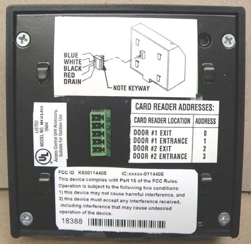
Click to zoom
Application Details
- Equipment Class
- DXT - Part 15 Low Power Transceiver, Rx Verified
- Date of Grant
- Feb 19, 2006
- Application Purpose
- Original Equipment
- Date of Application
- Feb 19, 2006
- Equipment Note
- Keypad Proximity Reader
- Frequency Range
- 13.56000000 - 13.56000000
- Company
- Matrix Systems Inc
- Country
- United States
Documents & Files
Document Text
Text extracted from the exhibit documents filed with the FCC. Open a document above to read the original.
Users Manual
RCM2 / MX-READER INSTALLATION MANUAL 2 The Reader Control Module is designed to interface with the Matrix family of card readers. The RCM2 provides access control and alarm point monitoring for up to two separate portals, providing entry and exit reader monitoring at each portal. 3 READER CONTROL MODULE (RCM2) AND RELATED COMPONENTS The Reader Control Module, model number 04-14000 is designed to interface with the Matrix family of card readers. These include the magnetic stripe card readers: MX1, MX2, and 01-14440 / 14441. The RCM2 will also interface to the proximity family of card readers: MX1-Prox, MX2-Prox, and the MX- iCLASS. The RCM2 provides access control and alarm point monitoring for up to two separate portals, providing entry and exit reader monitoring at each portal. WIRING CONSIDERATIONS Wiring between devices must be installed in a professional manner using any applicable local and national codes and using the following suggestions • For hollow wall construction, use ¾” electrical conduit or flexible metallic conduit. Minimally, the conduit should be extended from the reader location to above the ceiling. • For solid or hard surface construction, use ¾” electrical conduit or equally-sized metallic wire- mold. Plastic wire-way should not be used. When wiring the RCM2 to the host system and portal devices, care should be taken in using the appropriate cable. Matrix Systems provides custom cable with either a PVC jacket, part number 53-12009, or a plenum-rated Teflon jacket, part number 53-12010, as shown in the figure below. 22 AWG wire with shield and drain wire. Used for communications lines. Green / White used for lock power. 18 AWG wire Red / Black used for RCM / Reader power. 4 If substitute wire is used, it must meet the following criteria: • 2-pair, 22 AWG, individually shielded, West Penn part number 430 (PVC jacket), or part number 25430 (plenum rated), or equivalent. Use for RCM to Matrix host 4-wire RS-485 / 422 communications. • 4-conductor, 18 AWG, West Penn part number 244 (PVC jacket), or part number 25244 (plenum-rated), or equivalent. Use for Matrix host (data) signal ground, + 12 vdc power, and RCM device lock power. When explaining connections between devices, this manual will use the wire colors available with the Matrix Systems custom cable. Typical installations Control devices can be installed in a variety of configurations. The following pages lists samples of possible installations. Each of the following figures show how the respective device relates to the portal and other control devices. Typical conduit and wire usage is also shown in each figure. For specific information (mounting height, mounting method, wire color, etc.) refer to the sections: • READER CONTROL MODULE • MX-SERIES CARD READERS 5 Sample Installation – Single Door with Magnetic Door Contact RCM2 TO REMOTE DISTRIBUTION PANEL STUB ¾” CONDUIT INTO DOOR FRAME. INSTALL 1 WEST PENN #244 WIRE INTO CONDUIT INSTALL ¾” CONDUIT INSTALL 1 MATRIX 53-12009 CABLE DOOR POSITION SWITCH NOTE: INSTALL ON SECURE SIDE OF DOOR. MAINTAIN MINIMUM OF 2” FROM OTHER DEVICES MOUNTED ON DOOR. 6 Sample Installation – Single Door with Electric Strike, MX Card Reader at Entrance and Exit Button at Exit. INSTALL ¾” CONDUIT INSTALL 1 MATRIX 53-12009 CABLE STUB ¾” CONDUIT INTO DOOR FRAME. INSTALL 1 WEST PENN #244 WIRE INTO CONDUIT DOOR POSITION SWITCH ELECTRIC STRIKE INSTALL INTO DOOR FRAME. SEE INSTALLATION PROVIDED WITH LOCKS. EXIT BUTTON RCM2 INSTALL 4”X4”X2- 1/8” OUTLET BOX WITH DOUBLE GANG PLASTER RING FLUSH WITH OUTSIDE WALL SURFACE. INSTALL 1 WESTPENN #244 WIRE BETWEEN RCM AND EXIT BUTTON. INSTALL 4”X4”X2- 1/8” OUTLET BOX WITH DOUBLE GANG PLASTER RING FLUSH WITH OUTSIDE WALL SURFACE. INSTALL 1 MATRIX 53-12009 CABLE BETWEEN RCM AND READER TO REMOTE DISTRIBUTION PANEL MX CARD READER 7 Sample Installation – Single Door with Magnetic locks MX Card reader at Entrance and Motion Detector at Exit. TO REMOTE DISTRIBUTION PANEL INSTALL 4”X4”X2- 1/8” OUTLET BOX WITH DOUBLE GANG PLASTER RING FLUSH WITH OUTSIDE WALL SURFACE. INSTALL 1 MATRIX 53-12009 CABLE BETWEEN RCM AND READER RCM2 MOTION DETECTOR INSTALL ¾” CONDUIT TO SINGLE GANG BOX AND INSTALL WEST PENN #244 WIRE STUB ¾” CONDUIT INTO DOOR FRAME. INSTALL 1 WEST PENN #244 WIRE DOOR POSITION SWITCH MAGLOCK MX CARD READER INSTALL ¾” CONDUIT INSTALL 1 MATRIX 53-12009 CABLE 8 Connector J6 is used for RS-422 communication with the host. This is the default setting for the RCM2. Connector location on the RCM2 with input and output lines can be found in the Figure above. Connector J8 is used for RS-232 modem communication with the host. The use of the modem requires changes from the default jumper settings of the RCM2. Refer to the SETUP section for setting of jumpers JP3 and JP6. Connector location on the RCM2 with input and output lines can be found in the Figure above. Connector J10 is used to apply power to the RCM2. In most cases, power can be obtained from the RDP. If necessary, power from a local power supply can be connected to this connector. Connectors J11 and J12 are used to connect the RCM2 to MX-Series card readers. Internally, the connectors are wired in parallel and can be used combination for ease of wiring. The distinction between card readers is done with software when the system is set up. However, it is recommended that the readers be connected as groups (first door pair connected at J11 and second door pair connected at J12) to simplify the system for future reference J8 RS-232 J10 Power In put J11 READERS J12 READERS J6 RS-422 9 (TX) BLUE (RX) WHITE -12VDC BLACK +12VDC RED FRAME DRAIN GROUND NOTE KEYWAY READER CONTROL MODULE (RCM2) MX CARD READER BACK VIEW Function Color Code 10 MX CARD READER + 12VDC POWER SUPPLY EXPLODED VIEW OF PANIC BAR MAG-BOND W/STATUS SWITCH EXPLODED VIEW OF MAGNETIC LOCK 360 DOOR CONTRACT INPUT 1.8K N.C N.O. EGRESS MOTION DETECTOR INPUT 1 INPUT 3 1.8K 360 GND +12Vdc 11 MX – SERIES CARD READERS Matrix Systems Inc. manufactures and…
Text truncated - open the document above for the full version.
Block Diagram
Exciter Drive Circuit Antenna Microcontroller 13.56 MHz 13.56 MHz 13.56 MHz, 424 KHz, 848 KHz Crystal 13.56 MHz 26.5 KHz, 106 KHz M. Conlin 6/18/02 iClass OEM50 Block Diagram
Block Diagram
MATRIX SYSTEMS Keypad Proximity Reader Model MX-iCLASS Block Diagram Printed Circuit Board LCD Display Module Keypad Tamper Switch iCLASS Module iCLASS Antenna 4.9152MHz Crystal Micro- controller
Cover Letter(s)
www.HIDCorp.com 9292 Jeronimo Road • Irvine, CA 92618-1905 • Phone (949) 598-1600 Fax (949) 598-1680 (Administration) • Fax (949) 598-1690 (Customer Service) • Fax (949) 598-1692 (Manufacturing & Purchasing) An ASSA ABLOY Group company Reference: FCC ID: K830114405, IC: 6359A-0114405, Matrix Systems 0.459 & 0.457 Request that submitted material be withheld from Public Inspection Products: 31xxA iCLASS OEM Module Family It is requested that the following material be withheld from public inspection: Description of the iCLASS OEM Module, Circuit Functions, how the device operates, Ground System, and Antenna Block Diagram Schematic These materials are considered HID Corporation Proprietary and Confidential. Revealing the fundamental design for the product to the public, the OEM, and our competition would put us at a competitive disadvantage. We feel we have a product cost/design advantage over our competition with our iCLASS OEM Module family and therefore ask that the above-specified materials be withheld from public and OEM inspection. Frank de Vall Sr. Engineering Manager-Compliance HID Corporation Assa Abloy ITG Research and Development Center 11674 N. Huron Street Denver, CO 80234
External Photos
Matrix Systems Keypad Proximity Reader MX-iCLASS External Views We are in the process of changing our company logo and the look of the card reader. The outer shell on the left has rounded edges and a deeper texture. Both shells are made of plastic so they will not affect the RF characteristics of the card reader. We may use either outer shell in production. The back of the carder reader is enclosed by a metal plate.
ID Label/Location Info
Matrix Systems Keypad Proximity Reader MX-iCLASS External Views We are in the process of changing our company logo and the look of the card reader. The outer shell on the left has rounded edges and a deeper texture. Both shells are made of plastic so they will not affect the RF characteristics of the card reader. We may use either outer shell in production. The back of the carder reader is enclosed by a metal plate.
Internal Photos
1 Matrix Systems Keypad Proximity Reader MX-iCLASS Internal Views This is the rear view of the card reader with the metal back plate removed. A rubber gasket separates the printed circuit board form the back plate. This is the rear view with the rubber gasket removed. The top flex cable is to the LCD display module. The bottom flex cables are to the keypad and the tamper switch. 2 Matrix Systems Keypad Proximity Reader MX-iCLASS Internal Views The printed circuit board rests in a bathtub shaped plastic inner shell. This shows the printed circuit board removed from the inner shell and flipped over. This is the inner shell removed and flipped over, showing the placement of the antenna.
Operational Description
TECHNICAL REPORT HID CORPORATION 31xxA iCLASS™ OEM MODULES 2/10/06 This report concerns the Intentional Radiator and Antenna portions of a composite system that includes a computing device. Equipment Type: R.F. Identification Proximity Transmitter/Receiver Equipment Authorization: Part 15.201 Frequency of Operation: 13.56MHz Equipment Market: OEM Industrial Technical Report prepared by: Frank de Vall Assa Abloy Identification Technology Group & HID Corporation Denver Engineering Center 11658 N. Huron Street Denver, CO 80234-2905 (303) 453-4018 (303) 453-3340 FAX [email protected] 0.459 Request that submitted material be withheld from Public and OEM Inspection It is requested that the following material be withheld from public and OEM inspection: Description of 3100A, 3101A, 3111A, and 3131A iClass OEM Modules, Circuit Functions, how the device operates, Ground System, Antenna, Block Diagram, and Schematic. These materials are considered HID Corporation Proprietary and Confidential. Revealing the fundamental design for the product to the public and our competition would put us at a competitive disadvantage. We feel we have a product cost/design advantage over our competition with our iClass OEM Module family and therefore ask that the above specified materials be withheld from public inspection. 2.1033(b)(1) Full Name & Mailing Address of the Manufacturer HID Corporation 9292 Jeronimo Road Irvine, CA 92618-1905 2.1033(b)(4) Description of the iClass OEM Modules, Circuit Functions, how the device operates, Ground System, and Antennas Models Marketed and Sold 3100A (6091-301) iCLASS OEM 100/TTL 3101A (6091-301) iCLASS OEM 100/RS232 3111A (6092-301) iCLASS OEM 300 3131A (3131-300) iCLASS OEM 50 Differences between Models There are two antenna sizes for the OEM 100 and OEM300 and variable sizes for the OEM 50. See the antenna descriptions. All models have identical electronics except for Serial Interface capability. System Description & How the Device Operates The HID iClass OEM Module family of products are designed to be integrated into an OEM’s final or end product. The units are capable to read from or in some product configurations to write to EEPROM in a transponder IC with an RF interface at a distance of up to 5”. The transmitter/receiver antenna emits a 13.56MHz AC magnetic field. The field "powers up" a passive tag which is brought into the vicinity of the antenna. The tag, when powered, operates as a field disturbance device and either receives or returns a serial data stream. The iClass OEM Module devices receive power (10-16VDC) and commands from the OEM’s electronics. The iClass OEM Module has two modes of operation referred to as “HID mode” and “Pass-through mode”. When in HID mode, the units will normally be running with the RF field turned off. The RF field will be turned on every 100 milliseconds to poll for a transponder in the field. If there is no transponder in the field, the field will remain on for approximately 10 milliseconds and then turn off for the next 90 milliseconds. If there is a transponder in the field, the field will remain on for approximately 57 milliseconds while the reader reads the HID Access Control ID from the transponder. In Pass-through mode, the unit will receive commands over the serial port. If the command involves interaction with a transponder, the field will turn on until it completes the transaction. It will then remain on for 500 milliseconds after the last transponder transaction waiting for a subsequent command. After the 500 milliseconds has elapsed, the field turns off and remains off until the next command involving a transponder transaction comes in. Circuit Functions Please refer to the Block Diagram. All circuit blocks including the transmitter/receiver antenna are physically located on the printed circuit board for the OEM 100 and OEM 300. The antenna for the OEM 50 is off the board. For the OEM 100/RS232, the serial interface electronics are located on a small daughter board mounted to the main board. The 13.56 MHz crystal oscillator output is buffered through a pico-gate and is fed to the transmitter driver. The series and parallel tuning capacitors and antenna coil are tuned to provide a 50 ohm, 0 degree load at 13.56 MHz. When this circuit is turned on, a modulated 13.56 MHz AC Magnetic field is radiated from the antenna. When a transponder enters the field, it is powered by the RF field from the reader/writer device. If this causes the transponder to “wake-up”, the transponder will now load modulate the field to send its responses/data back to the reader/writer unit. Ground System The transmitter driver circuitry, analog circuitry and digital circuitry all connect to the same ground plane. Antennas The transmit/receive antenna consist of a few turn loop antenna etched into an inner layer of the board. The antenna areas are: 3100A 3101A 0.0026 m 2 3111A 0.0039 m 2 3131A OEM Designed
Test Report
Page 1 of 35 Report No.: FC06-014 MATRIX SYSTEMS TEST REPORT FOR THE KEYPAD PROXIMITY READER, MX-ICLASS FCC PART 15 SUBPART C SECTIONS 15.207, 15.209, 15.225 AND RSS-210 COMPLIANCE DATE OF ISSUE: FEBRUARY 8, 2006 PREPARED FOR: Matrix Systems 7550 Paragon Road Dayton, OH 45459 PREPARED BY: Mary Ellen Clayton CKC Laboratories, Inc. 5046 Sierra Pines Drive Mariposa, CA 95338 P.O. No.: 7872 W.O. No.: 84699 Date of test: February 2-7, 2006 Report No.: FC06-014 This report contains a total of 35 pages and may be reproduced in full only. Partial reproduction may only be done with the written consent of CKC Laboratories, Inc. The results in this report apply only to the items tested, as identified herein. Page 2 of 35 Report No.: FC06-014 TABLE OF CONTENTS Administrative Information .............................................................................................3 FCC to Canada Standard Correlation Matrix...................................................................4 Conditions for Compliance ..............................................................................................4 Approvals .........................................................................................................................4 FCC 15.31(m) Number Of Channels ...............................................................................5 FCC 15.33(a) Frequency Ranges Tested .........................................................................5 FCC 15.35 Analyzer Bandwidth Settings ........................................................................5 FCC 15.203 Antenna Requirements ................................................................................5 Eut Operating Frequency .................................................................................................5 Temperature And Humidity During Testing....................................................................5 Equipment Under Test (EUT) Description ......................................................................6 Equipment Under Test .....................................................................................................6 Peripheral Devices ...........................................................................................................6 Report of Measurements ..................................................................................................7 Table 1: FCC 15.207 Six Highest Conducted Emission Levels ..........................7 Table 2: FCC 15.209 Radiated Emission Levels: 9 kHz - 30 MHz.....................8 Table 3: FCC 15.209 Six Highest Radiated Emission Levels: 30-1000 MHz.....9 Table 4: FCC 15.225(a) Fundamental Emission Levels ......................................10 FCC 15.225(a) Emissions Mask ..........................................................................11 FCC 15.225(a) and RSS-210 Occupied Bandwidth Plot .....................................12 FCC 15.31(e) Voltage Variations and 15.225(e) Frequency Stability.................13 EUT Setup........................................................................................................................14 Correction Factors............................................................................................................14 Table A: Sample Calculations .............................................................................14 Test Instrumentation and Analyzer Settings ....................................................................15 Spectrum Analyzer Detector Functions ...............................................................15 Peak..........................................................................................................15 Quasi-Peak ...............................................................................................15 Average ....................................................................................................15 EUT Testing.....................................................................................................................16 Mains Conducted Emissions................................................................................16 Radiated Emissions ..............................................................................................16 Appendix A: Test Setup Photographs..............................................................................17 Photograph Showing Mains Conducted Emissions .............................................18 Photograph Showing Mains Conducted Emissions .............................................19 Photograph Showing Radiated Emissions ...........................................................20 Photograph Showing Radiated Emissions ...........................................................21 Photograph Showing Temperature Testing .........................................................22 Appendix B: Test Equipment List ...................................................................................23 Appendix C: Measurement Data Sheets ..........................................................................24 Page 3 of 35 Report No.: FC06-014 ADMINISTRATIVE INFORMATION DATE OF TEST: February 2-7, 2006 DATE OF RECEIPT: February 2, 2006 MANUFACTURER: Matrix Systems 7550 Paragon Road Dayton, OH 45459 REPRESENTATIVE: Mark Stabler TEST LOCATION: CKC Laboratories, Inc. 5046 Sierra Pines Drive Mariposa, CA 95338 TEST METHOD: ANSI C63.4 (2003), RSS-210 and RSS-GEN PURPOSE OF TEST: To demonstrate the compliance of the Keypad Proximity Reader, MX-iCLASS with the requirements for FCC Part 15 Subpart C Sections 15.207, 15.209, 15.225 and RSS-210 devices. Page 4 of 35 Report No.: FC06-014 FCC TO CANADA STANDARD CORRELATION MATRIX Canadian Standard Canadian Section FCC Standard FCC Section Test Description RSS 2105.547CFR15.203Antenna Connector Requirements RSS 2106.2.147CFR15.209General Radiated Emissions Requirement RSS 2106.2.2(e)47CFR15.225(a)* Fundamental Require…
Text truncated - open the document above for the full version.
Test Setup Photos
PHOTOGRAPH SHOWING MAINS CONDUCTED EMISSIONS Mains Conducted Emissions - Front View PHOTOGRAPH SHOWING MAINS CONDUCTED EMISSIONS Mains Conducted Emissions - Side View PHOTOGRAPH SHOWING RADIATED EMISSIONS Radiated Emissions - Front View PHOTOGRAPH SHOWING RADIATED EMISSIONS Radiated Emissions - Back View PHOTOGRAPH SHOWING TEMPERATURE TESTING
Contact Information
Applicant
Mark Stabler(Design Engineer)
Technical Contact
CKC Laboratories, Inc.Mary Ellen Clayton
[email protected]800-500-4362
5046 Sierra Pines Drive · Mariposa, California · United States
Test Firm
CKC Laboratories, Inc.Steve Behm
Technical Specifications
| # | Rule Parts | Frequency Range | Power Output |
|---|---|---|---|
| 1 | 15C | 13.56 MHz - 13.56 MHz | - |
Other Applications from Matrix Systems Inc
K830112093
Feb 27, 1994Proximity Card Reader
Equipment Class
DCD - Part 15 Low Power Transmitter Below 1705 kHz