K88-92021"Kaddy Link" Remote control unit
Lectronic Kaddy Corporation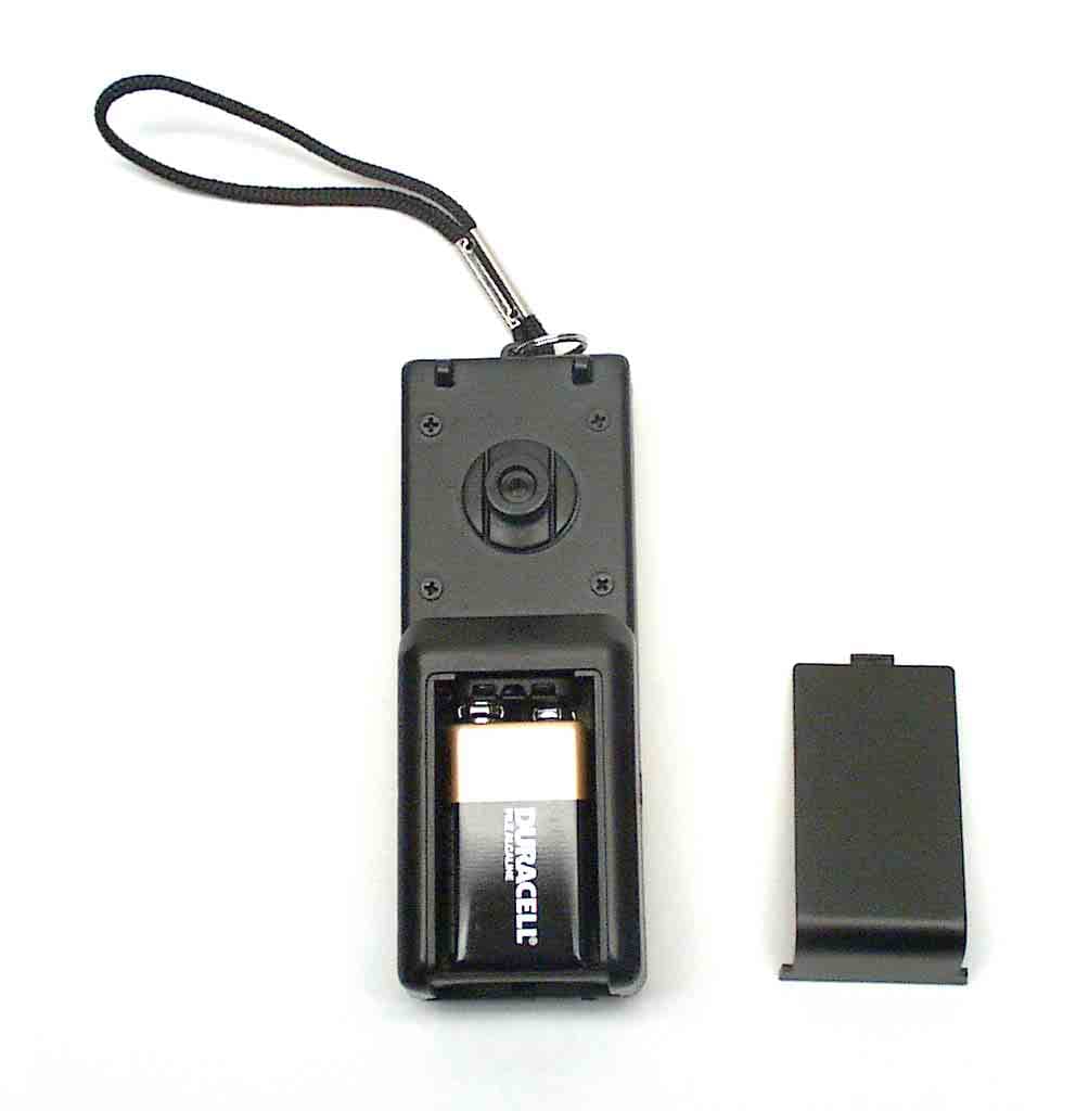
Click to zoom
Application Details
- Equipment Class
- DSC - Part 15 Security/Remote Control Transmitter
- Date of Grant
- Jul 29, 2003
- Application Purpose
- Original Equipment
- Date of Application
- Jul 29, 2003
- Equipment Note
- "Kaddy Link" Remote control unit
- Frequency Range
- 433.42000000 - 434.42000000
- Company
- Lectronic Kaddy Corporation
- Country
- Canada
Documents & Files
Document Text
Text extracted from the exhibit documents filed with the FCC. Open a document above to read the original.
Users Manual
Quick Start To get your game up and running quickly with for more comprehensive instructions refer to your owners manual Manual FCC Information to UsersThis equipment has been tested and found to comply with thelimits for a class B digital device, pursuant to Part 15 of the FCCRules. These limits are designed to provide reasonableprotection against harmful interference in a residentialinstallation. This equipment generates, uses, and can radiateradio frequency energy and, if not installed and used inaccordance with the instruction manual, may cause harmfulinterference to radio communications However, there is noguarantee that the interference will not occur in a particularinstallation. If this equipment does cause harmful interference toradio or television reception, which can be determined by turningthe equipment off and on, the user is encouraged to try tocorrect the interference by one or more of the followingmeasures: Reorientate or relocate the receiving antenna. Increase the separation between the equipment and receiver. Connect the equipment into an outlet on a circuit different from that to which the receiver is connected. Consult the dealer or an experienced radio/TV technician for help. Warning: Changes or modifications not expressly approved byLectronic Kaddy Corporation could void the user's authority tooperate the equipment. Manual Operation Connect battery and ensure that the plug issecurely inserted into the socket.Press "On" button to power up the ‘Kaddy. From the main control panel:-Pressing the green bar ("Start") will start the ‘Kaddy moving.Pressing the red bar ("Dynamic Brake") willstop the kaddy by applying the brakes. For moving short distances , depress and hold the manual push button located underthe hand grip, release to stop. For more functions, refer to the instruction manual. Data Panel illustration Here To start the ‘Kaddy using your remote control, hand held, transmitter, simply press the centre round button.(see illustration) Holding down this button willgradually increase the speed of the ‘Kaddy. Release the button when thedesired speed has been reached, the ‘Kaddy will then maintain this speed.To stop the ‘Kaddy, press the lower round button once. This will disengage power to the motors. Continuing to hold down this button, or pressing a secondtime, will cause the brakes to activate.To initiate a turn , press, and hold down, the toggle switch either to the right, to initiate a right turn, or to the left for a left turn.Initiating the turn when the ‘Kaddy is already in motion, will result in gentleturning or course correction. If a more aggressive turn is required, then first stop the ‘Kaddy then press and hold the toggle switch either left or right.Release the toggle switch to allow the ‘Kaddy to revert to a straight path.If turning was initiated after stopping the ‘Kaddy, then, upon releasing the turncommand, the ‘Kaddy speed will revert to the lowest setting and it will benecessary to increase speed by pressing the centre round button as describedin the starting procedure. Remote Operation Operating Tips When traveling down hill, the ‘Kaddy will not turn as effectively. This ensures that the ‘Kaddy will remain stable at all times. To effect turns inthese circumstances, first stop the ‘Kaddy prior to activating the turn, asdescribed above. When traveling up hill, the ‘Kaddy will be more responsive when turning. Take care when maneuvering in these circumstances, especiallywhen near hazzards. If in doubt, revert to manual control. The effective range of transmission can be effected by environmental conditions. If the ‘Kaddy becomes "out of range", raising the transmitterabove your head and activating the stop button will bring the ‘Kaddy torest. If you park the ‘Kaddy and leave it unattended, switch off the power at the ‘Kaddy's Control Panel. Other ‘Kaddy users with the same user codesetting and/or inadvertent operation of the transmitter buttons when out ofsight of your ‘Kaddy, can cause the ‘Kaddy to be set in motion. If the LED light on the transmitter appears as a solid light, instead of flashing rapidly, when a button is pressed, then the 9 volt battery in thetransmitter needs to be replaced immediately. Failure to do so may result inyour losing control of the ‘Kaddy. L.E.D. 9V Battery Strap Front Start/Speed Stop/Brake User Code Back Tu r n Transmitter Illustr. Replace Battery Open the transmitter case by sliding the battery cover to expose the battery. Remove thebattery and disengage the polarized connector. Do not stress the wires by dangling thebattery while still connected. Replace the battery with the specified alkaline battery.Replace the cover. Setting User Code The user code has already been set for your unit and, therefore, does not requireadjustment. However should it become necessary to change or reset the code, thefollowing should be observed.The transmitter and receiver must have the identical User Code to communicate. The UserCode is a numerical representation of the switch settings. e.g. "123" indicates that switches#1, #2, & #3 are in the "on" position, all other switches being "off". To set the transmittercode, remove the battery to expose the switches.(see illustration) Using a pointed tool, oreven a golf tee, switch the appropriate switches to the "on" position.To change the receiver code, to avoid conflict with another user for instance, the receivermust be removed from the ‘Kaddy, opened to expose the set of switches and the switchpositions modified as described for the transmitter. Mark the new code on the receiverenclosure for future reference. Reset the transmitter code as described above. Remote Spec. Transmitter Specification Receiver Specification :-
Cover Letter(s)
June 20 th 2003 FEDERAL COMMUNICATIONS COMMISSION 7435 Oakland Mills Road Columbia, MD 21046 U.S.A. Subject: Request for withholding from public disclosure the schematic diagrams and system block diagrams pursuant to an application for certification. Applicant:Lectronic Kaddy Corporation Product:“Kaddy-Link” remote control unit Model: FCC ID: Dear Sir/Madam, We ,LectronicKaddyCorporation, would like to request that the schematic diagrams, system block diagrams, parts list and operational description, submitted with the application for certification be withheld from public disclosure as per Section 0.459 of FCC Rules. This request is made under the provisions of Section 0.457(d) of the Commission's Rules, and Section 552(b)(4) of the Freedom of Information Act. These sections authorize as a withholding from public inspection, materials which would be privileged as a matter of law if retained by the person submitting them, and materials which would not customarily be released to the public by that person. If you have any queries, please do not hesitate to contact us by our TOLL FREE numbers: OUR TELEPHONE NO.: 1-800-267-0098 Yours truly, Frank A. Eilles V.P. & General Manager #92021 Transmitter K88 - 92021
External Photos
ANNEX 2 – EXTERNAL EUT PHOTOS Lectronic Kaddy Corporation “Kaddy-Link” Remote Control Unit, Model #92021 Transmitter FCC ID: K88-92021 IC: 2166A-92021 A2 - 1 ANNEX 2 – EXTERNAL EUT PHOTOS Lectronic Kaddy Corporation “Kaddy-Link” Remote Control Unit, Model #92021 Transmitter FCC ID: K88-92021 IC: 2166A-92021 A2 - 2 ANNEX 2 – EXTERNAL EUT PHOTOS Lectronic Kaddy Corporation “Kaddy-Link” Remote Control Unit, Model #92021 Transmitter FCC ID: K88-92021 IC: 2166A-92021 A2 - 3 ANNEX 2 – EXTERNAL EUT PHOTOS Lectronic Kaddy Corporation “Kaddy-Link” Remote Control Unit, Model #92021 Transmitter FCC ID: K88-92021 IC: 2166A-92021 A2 - 4 ANNEX 2 – EXTERNAL EUT PHOTOS Lectronic Kaddy Corporation “Kaddy-Link” Remote Control Unit, Model #92021 Transmitter FCC ID: K88-92021 IC: 2166A-92021 A2 - 5
ID Label/Location Info
This device complies with part 15 of the FCC Rules. Operation is subject to the folowing two conditions: (1) this device may not cause harmful interference and (2) this device must accept any interference received, including interference that may cause undesired operation. FCC ID: K88 - 92021 Part # Description Rev.BySize Label FCC FAE 1 June 20 2003 DateScale F.S. 1.6" 1.0" 3234 IC: 2166A - 92021 Transmitter #92021 ID label placement
Internal Photos
ANNEX 3 – INTERNAL EUT PHOTOS Lectronic Kaddy Corporation “Kaddy-Link” Remote Control Unit, Model #92021 Transmitter FCC ID: K88-92021 IC: 2166A-92021 A3 - 1 ANNEX 3 – INTERNAL EUT PHOTOS Lectronic Kaddy Corporation “Kaddy-Link” Remote Control Unit, Model #92021 Transmitter FCC ID: K88-92021 IC: 2166A-92021 A3 - 2 ANNEX 3 – INTERNAL EUT PHOTOS Lectronic Kaddy Corporation “Kaddy-Link” Remote Control Unit, Model #92021 Transmitter FCC ID: K88-92021 IC: 2166A-92021 A3 - 3
Test Report
"Kaddy-Link" Remote Control Unit Model No.: #92021 Transmitter FCC ID: K88-92021 Applicant: Lectronic Kaddy Corporation 4626 Burgoyne Street Mississauga, Ontario Canada, L4W 1G1 In Accordance With Federal Communications Commission (FCC) Part 15, Subpart C, Section 15.231 Momentarily Operated Transmitters (433.92 MHz) UltraTech's File No.: LEC-009F15C231 This Test report is Issued under the Authority of Tri M. Luu, Professional Engineer, Vice President of Engineering UltraTech Group of Labs Date: July 23, 2003 Report Prepared by: Dan Huynh Issued Date: July 23, 2003 Tested by: Mr. Hung Trinh, EMI/RFI Technician Test Dates: June 20, 2003 ! The results in this Test Report apply only to the sample(s) tested, and the sample tested is randomly selected. ! This report must not be used by the client to claim product endorsement by NVLAP or any agency of the US Government. UltraTech 3000 Bristol Circle, Oakville, Ontario, Canada, L6H 6G4 Tel.: (905) 829-1570 Fax.: (905) 829-8050 Website: www.ultratech-labs.com , Email: [email protected], Email: [email protected] 2 31040/SIT C-1376 46390-2049 200093-0 SL2-IN-E-1119R 00-034 FCC Part 15, Subpart C, Section 15.231, Periodic Operation Contents i "Kaddy-Link" Remote Control Unit, Model No.: #92021 Transmitter FCC ID: K88-92021 ULTRATECH GROUP OF LABS File #: LEC-009F15C231 3000 Bristol Circle, Oakville, Ontario, Canada L6H 6G4 July 23, 2003 Tel. #: 905-829-1570, Fax. #: 905-829-8050, Email: [email protected] , Website: http://www.ultratech-labs.com All test results contained in this engineering test report are traceable to National Institute of Standards and Technology (NIST) TABLE OF CONTENTS EXHIBIT 1: SUBMITTAL CHECK LIST...................................................................................................................... 1 EXHIBIT 2: INTRODUCTION ....................................................................................................................................... 2 2.1. SCOPE....................................................................................................................................................................... 2 2.2. RELATED SUBMITTAL(S)/GRANT(S) ................................................................................................................ 2 2.3. NORMATIVE REFERENCES ................................................................................................................................. 2 EXHIBIT 3: PERFORMANCE ASSESSMENT ............................................................................................................ 3 3.1. CLIENT INFORMATION ........................................................................................................................................ 3 3.2. EQUIPMENT UNDER TEST (EUT) INFORMATION ..........................................................................................3 3.3. EUT’S TECHNICAL SPECIFICATIONS ............................................................................................................... 4 3.4. GENERAL TEST SETUP......................................................................................................................................... 5 EXHIBIT 4: EUT OPERATING CONDITIONS AND CONFIGURATIONS DURING TESTS ............................. 6 4.1. CLIMATE TEST CONDITIONS ............................................................................................................................. 6 4.2. OPERATIONAL TEST CONDITIONS & ARRANGEMTNT FOR TESTS .......................................................... 6 EXHIBIT 5: SUMMARY OF TEST RESULTS ............................................................................................................. 7 5.1. LOCATION OF TESTS............................................................................................................................................ 7 5.2. APPLICABILITY & SUMMARY OF EMC EMISSION TEST RESULTS ........................................................... 7 5.3. MODIFICATIONS INCORPORATED IN THE EUT FOR COMPLIANCE PURPOSES..................................... 7 EXHIBIT 6: MEASUREMENTS, EXAMINATIONS & TEST DATA FOR EMC EMISSIONS............................. 8 6.1. TEST PROCEDURES............................................................................................................................................... 8 6.2. MEASUREMENT UNCERTAINTIES .................................................................................................................... 8 6.3. MEASUREMENT EQUIPMENT USED ................................................................................................................. 8 6.4. ESSENTIAL/PRIMARY FUNCTIONS AS DECLARED BY THE MANUACTURER........................................ 8 6.5. ANTENNA REQUIREMENTS [47 CFR § 15.203]................................................................................................. 8 6.6. PROVISIONS FOR PERIODIC OPERATION [47 CFR § 15.231(A)].................................................................... 9 6.7. TRANSMITTER RADIATED EMISSIONS @ 3 METERS [47 CFR §§ 15.231(B), 15.209 & 15.205] .............. 10 6.8. EMISSION BANDWIDTH [47 CFR § 15.231(C)]................................................................................................. 15 EXHIBIT 7: MEASUREMENT UNCERTAINTY....................................................................................................... 18 7.1. RADIATED EMISSION MEASUREMENT UNCERTAINTY ............................................................................ 18 EXHIBIT 8: MEASUREMENT METHODS ................................................................................................................ 19 8.1. GENERAL TEST CONDITIONS .......................................................................................................................... 19 8.2. METHOD OF MEASUREMENTS - AC MAINS CONDUCTED EMISSIONS ....................................…
Text truncated - open the document above for the full version.
Test Setup Photos
ANNEX 1 - TEST SETUP PHOTOS Lectronic Kaddy Corporation “Kaddy-Link” Remote Control Unit, Model #92021 Transmitter FCC ID: K88-92021 IC: 2166A-92021 A1 - 1 ANNEX 1 - TEST SETUP PHOTOS Lectronic Kaddy Corporation “Kaddy-Link” Remote Control Unit, Model #92021 Transmitter FCC ID: K88-92021 IC: 2166A-92021 A1 - 2 ANNEX 1 - TEST SETUP PHOTOS Lectronic Kaddy Corporation “Kaddy-Link” Remote Control Unit, Model #92021 Transmitter FCC ID: K88-92021 IC: 2166A-92021 A1 - 3 ANNEX 1 - TEST SETUP PHOTOS Lectronic Kaddy Corporation “Kaddy-Link” Remote Control Unit, Model #92021 Transmitter FCC ID: K88-92021 IC: 2166A-92021 A1 - 4 ANNEX 1 - TEST SETUP PHOTOS Lectronic Kaddy Corporation “Kaddy-Link” Remote Control Unit, Model #92021 Transmitter FCC ID: K88-92021 IC: 2166A-92021 A1 - 5 ANNEX 1 - TEST SETUP PHOTOS Lectronic Kaddy Corporation “Kaddy-Link” Remote Control Unit, Model #92021 Transmitter FCC ID: K88-92021 IC: 2166A-92021 A1 - 6
Contact Information
Applicant
Gordon Watt
Test Firm
UltraTech Engineering Labs Inc.Tri Luu
Technical Specifications
| # | Rule Parts | Frequency Range | Power Output | Emission |
|---|---|---|---|---|
| 1 | 15.231 | 433.42 MHz - 434.42 MHz | - | 95K0K1D |
Other Applications from Lectronic Kaddy Corporation
K88-9201
Mar 20, 1994Remote Control Receiver for a golf kaddy.
Equipment Class
CYY - Communications Receiver used w/Pt 15 TransmitterK88-9202
Mar 20, 1994Remote Control Transmitter
Equipment Class
DSC - Part 15 Security/Remote Control Transmitter