KA22001120011-1Wireless LAN CardBus PC Card
D-Link Corporation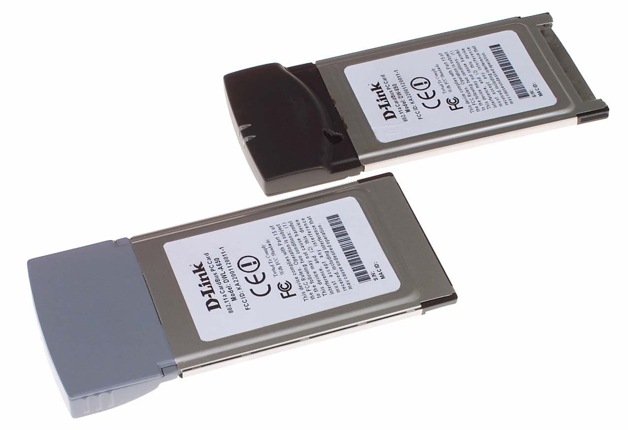
Click to zoom
Application Details
- Equipment Class
- NII - Unlicensed National Information Infrastructure TX
- Date of Grant
- Feb 23, 2002
- Application Purpose
- Original Equipment
- Date of Application
- Feb 23, 2002
- Equipment Note
- Wireless LAN CardBus PC Card
- Frequency Range
- 5210.00000000 - 5290.00000000
- Company
- D-Link Corporation
- Country
- United States
Documents & Files
Document Text
Text extracted from the exhibit documents filed with the FCC. Open a document above to read the original.
Users Manual
i DW-690 & DWL-A650 5GHz Wireless Cardbus Card User’s Manual First Edition (December, 2001) 6DWLA650..01 Wichtige Sicherheitshinweise 1. Bitte lesen Sie sich diese Hinweise sorgfältig durch. 2. Heben Sie diese Anleitung für den spätern Gebrauch auf. 3. Vor jedem Reinigen ist das Gerät vom Stromnetz zu trennen. Vervenden Sie keine Flüssig- oder Aerosolreiniger. Am besten dient ein angefeuchtetes Tuch zur Reinigung. 4. Um eine Beschädigung des Gerätes zu vermeiden sollten Sie nur Zubehörteile verwenden, die vom Hersteller zugelassen sind. 5. Das Gerät is vor Feuchtigkeit zu schützen. 6. Bei der Aufstellung des Gerätes ist auf sichern Stand zu achten. Ein Kippen oder Fallen könnte Verletzungen hervorrufen. Verwenden Sie nur sichere Standorte und beachten Sie die Aufstellhinweise des Herstellers. 7. Die Belüftungsöffnungen dienen zur Luftzirkulation die das Gerät vor Überhitzung schützt. Sorgen Sie dafür, daß diese Öffnungen nicht abgedeckt werden. 8. Beachten Sie beim Anschluß an das Stromnetz die Anschlußwerte. 9. Die Netzanschlußsteckdose muß aus Gründen der elektrischen Sicherheit einen Schutzleiterkontakt haben. 10. Verlegen Sie die Netzanschlußleitung so, daß niemand darüber fallen kann. Es sollete auch nichts auf der Leitung abgestellt werden. 11. Alle Hinweise und Warnungen die sich am Geräten befinden sind zu beachten. 12. Wird das Gerät über einen längeren Zeitraum nicht benutzt, sollten Sie es vom Stromnetz trennen. Somit wird im Falle einer Überspannung eine Beschädigung vermieden. 13. Durch die Lüftungsöffnungen dürfen niemals Gegenstände oder Flüssigkeiten in das Gerät gelangen. Dies könnte einen Brand bzw. Elektrischen Schlag auslösen. 14. Öffnen Sie niemals das Gerät. Das Gerät darf aus Gründen der elektrischen Sicherheit nur von authorisiertem Servicepersonal geöffnet werden. 15. Wenn folgende Situationen auftreten ist das Gerät vom Stromnetz zu trennen und von einer qualifizierten Servicestelle zu überprüfen: a – Netzkabel oder Netzstecker sint beschädigt. b – Flüssigkeit ist in das Gerät eingedrungen. c – Das Gerät war Feuchtigkeit ausgesetzt. d – Wenn das Gerät nicht der Bedienungsanleitung ensprechend funktioniert oder Sie mit Hilfe dieser Anleitung keine Verbesserung erzielen. e – Das Gerät ist gefallen und/oder das Gehäuse ist beschädigt. f – Wenn das Gerät deutliche Anzeichen eines Defektes aufweist. 16. Bei Reparaturen dürfen nur Orginalersatzteile bzw. den Orginalteilen entsprechende Teile verwendet werden. Der Einsatz von ungeeigneten Ersatzteilen kann eine weitere Beschädigung hervorrufen. iii 17. Wenden Sie sich mit allen Fragen die Service und Repartur betreffen an Ihren Servicepartner. Somit stellen Sie die Betriebssicherheit des Gerätes sicher. 18. Zum Netzanschluß dieses Gerätes ist eine geprüfte Leitung zu verwenden, Für einen Nennstrom bis 6A und einem Gerätegewicht großer 3kg ist eine Leitung nicht leichter als H05VV-F, 3G, 0.75mm2 einzusetzen Limited Warranty Hardware: D-LINK WARRANTS EACH OF ITS HARDWARE PRODUCTS TO BE FREE FROM DEFECTS IN WORKMANSHIP AND MATERIALS UNDER NORMAL USE AND SERVICE FOR A PERIOD COMMENCING ON THE DATE OF PURCHASE FROM D-LINK OR ITS AUTHORIZED RESELLER AND EXTENDING FOR THE LENGTH OF TIME STIPULATED BY THE AUTHORIZED RESELLER OR D-LINK BRANCH OFFICE NEAREST TO THE PLACE OF PURCHASE. THIS WARRANTY APPLIES ON THE CONDITION THAT THE PRODUCT REGISTRATION CARD IS FILLED OUT AND RETURNED TO A D-LINK OFFICE WITHIN NINETY (90) DAYS OF PURCHASE. A LIST OF D-LINK OFFICES IS PROVIDED AT THE BACK OF THIS MANUAL, TOGETHER WITH A COPY OF THE REGISTRATION CARD. IF THE PRODUCT PROVES DEFECTIVE WITHIN THE APPLICABLE WARRANTY PERIOD, D-LINK WILL PROVIDE REPAIR OR REPLACEMENT OF THE PRODUCT. D-LINK SHALL HAVE THE SOLE DISCRETION WHETHER TO REPAIR OR REPLACE, AND REPLACEMENT PRODUCT MAY BE NEW OR RECONDITIONED. REPLACEMENT PRODUCT SHALL BE OF EQUIVALENT OR BETTER SPECIFICATIONS, RELATIVE TO THE DEFECTIVE PRODUCT, BUT NEED NOT BE IDENTICAL. ANY PRODUCT OR PART REPAIRED BY D-LINK PURSUANT TO THIS WARRANTY SHALL HAVE A WARRANTY PERIOD OF NOT LESS THAN 90 DAYS, FROM DATE OF SUCH REPAIR, IRRESPECTIVE OF ANY EARLIER EXPIRATION OF ORIGINAL WARRANTY PERIOD. WHEN D-LINK PROVIDES REPLACEMENT, THEN THE DEFECTIVE PRODUCT BECOMES THE PROPERTY OF D-LINK. WARRANTY SERVICE MAY BE OBTAINED BY CONTACTING A D-LINK OFFICE WITHIN THE APPLICABLE WARRANTY PERIOD, AND REQUESTING A RETURN MATERIAL AUTHORIZATION (RMA) NUMBER. IF A REGISTRATION CARD FOR THE PRODUCT IN QUESTION HAS NOT BEEN RETURNED TO D-LINK , THEN A PROOF OF PURCHASE (SUCH AS A COPY OF THE DATED PURCHASE INVOICE) MUST BE PROVIDED. IF PURCHASER’S CIRCUMSTANCES REQUIRE SPECIAL HANDLING OF WARRANTY CORRECTION, THEN AT THE TIME OF REQUESTING RMA NUMBER, PURCHASER MAY ALSO PROPOSE SPECIAL PROCEDURE AS MAY BE SUITABLE TO THE CASE. AFTER AN RMA NUMBER IS ISSUED, THE DEFECTIVE PRODUCT MUST BE PACKAGED SECURELY IN THE ORIGINAL OR OTHER SUITABLE SHIPPING PACKAGE TO ENSURE THAT IT WILL NOT BE DAMAGED IN TRANSIT, AND THE RMA NUMBER MUST BE PROMINENTLY MARKED ON THE OUTSIDE OF THE PACKAGE. THE PACKAGE MUST BE MAILED OR OTHERWISE SHIPPED TO D-LINK WITH ALL COSTS OF MAILING/SHIPPING/INSURANCE PREPAID. D- LINK SHALL NEVER BE RESPONSIBLE FOR ANY SOFTWARE, FIRMWARE, INFORMATION, OR MEMORY DATA OF PURCHASER CONTAINED IN, STORED ON, OR INTEGRATED WITH ANY PRODUCT RETURNED TO D-LINK PURSUANT TO THIS WARRANTY. ANY PACKAGE RETURNED TO D-LINK WITHOUT AN RMA NUMBER WILL BE REJECTED AND SHIPPED BACK TO PURCHASER AT PURCHASER’S EXPENSE, AND D-LINK RESERVES THE RIGHT IN SUCH A CASE TO LEVY A REASONABLE HANDLING CHARGE IN ADDITION MAILING OR SHIPPING COSTS. Software: WARRANTY SERVICE FOR SOFTWARE PRODUCTS MAY BE OBTAINED BY CONTACTING A D-LINK OFFICE WITHIN THE APPLICABLE WARRANTY PERIOD. A LIST OF D-LINK OFFICES IS PROVIDED AT THE BACK OF THIS MANUAL, TOGETHER WITH A COPY OF THE REGISTRATION CARD. IF A REGISTRATION CARD FOR THE PRODUCT IN QUESTION HAS NOT BEEN RETURNED TO A D-LINK OFFICE, THEN A PROOF OF PURCHASE (SUCH AS A COPY OF T…
Text truncated - open the document above for the full version.
Cover Letter(s)
Page 1 of 3 RE: D Link Corporation FCC ID: KA22001120011-1 1) The FCC ID specified on the label and the test report does not match the ID given on the 731 form. Please comment on which ID is to be used and correct the appropriate paperwork. The correct ID is KA22001120011-1. The Form 731 has been amended appropriately. 2) The device is listed as Class B regarding digital device emissions, however page 4 of 61 states that measurements from 30 - 1000 MHz were made at 10 meters. Please comment. The Class B tests were performed at 3m. The test data has been revised to correct the mistake. The revised report and associated data have been uploaded. 3) The theory of operation states that the EUT uses 8 channels between 5180-5320, while the sales literature states 11 channels. Please explain. Literature has been revised to reflect only 8 channels for US and Canada. 4) The EUT seems to have much less power (almost 10 dB) than the level output by the PA (specified in the theory of operation). Please comment. The PA is capable of much more power. At the higher power levels the band-edge and harmonics no longer meet the FCC’s rules. The power limitation is due, therefore, to the FCC’s requirements rather than the limitations of the PA. Taken out from the Revised Theory of Operation (Section 2.7): The PA has 29.5dB nominal gain and maximum output power of 22.5dBm.Due to the highly linearity restrict of the high level modulation scheme, The PA normally operating on a linearity region of 10 to17 dBm output power, This device draws about 180mA when enabled by the XPAA signal. 5) Please show where the statements “Radio Frequency interference requirements: The device is restricted to indoor use only. FCC requires this product to be used indoors due to its operation in the frequency range 5.15 to 5.25 GHz.“ may be found in the manual. The User’s Manual has been updated to include this statement. The revised manual has been uploaded. The statement’s can be found on page 7 of 136. Page 2 of 3 6) It appears in the manual that the software allows a pull down menu to program the unit for use on different frequency sets for U.S., Canada, and Japan. This control capability should normally not be given to the end user if it will cause the radio to transmit on frequencies not authorized in the U.S. The FCC has recently stated in a Report and Order regarding software defined radios that the manufacturer will be held responsible for keeping the integrity of its programming intact. If the device could be hacked or programmed in an unauthorized manner, the responsibility for such action would rest with the manufacturer, and the FCC would go to the manufacturer for fines or forfeiture actions if either action were necessary. The FCC has further explained to TCBs to also apply the philosophy of the R&O with regard to protecting multiple-capable programming and existing devices that they are approving (not just software defined radios). Please comment. This control capability will not be available to the end-user and will be removed form the manual. Old manual had Chapter 9 for Country selection. This has been removed on the revised user manual. 7) Given that the highest power actually occurs on the center channel (5250 MHz) and not limited to the 5150-5250 or 5250-5350 band, the grant will be listed as 5210 MHz - 5290 MHz @ 28 mW & 5180 MHz - 5320MHz @ 21 mW. Please adjust the 731 form to match. Form 731 has been revised an uploaded to the ATCB web site.. 8) The test report shows several margins of 0.1 dB for both radiated and PSD tests. Is D Link Corporation comfortable with this margin? D-Link Letter of acceptance has been uploaded 9) Under antenna requirements (page 8 of 18) the report states 15.15 - 15.25 GHz which is not correct. The power spectral density on the summary page (page 5 of 18) for turbo does not match test report page 10 of 61 (is missing the negative sign). The plot on page 56 of 61 states 54.0 dB for the average measurement, while the note states 50.3 dB. Please correct these errors to ensure consistency in the report. The corrections have been made and revised report uploaded to the ATCB web site. Hopefully this answers all of your questions. Please contact me via [email protected] if you require more information. Regards, Mark Briggs Page 3 of 3 Director of Engineering
External Photos
EXTERNAL PHOTOGRAPHS The following external photographs show the top and bottom of the two versions of the CardBus device.
ID Label/Location Info
This device complies with Part 15 of the FCC Rules. Operation is subject to the following two conditions: (1) This device may not cause harmful interference, and (2) this device must accept any interference received, including interference that may cause undesired operation. CE Te s t ed To Co m ply W i t h CC F S t a n da r ds Model: DW-690 802.11a CardBus PC Card FCC ID: KA22001120011-1 S/N: MAC ID: This device complies with Part 15 of the FCC Rules. Operation is subject to the following two conditions: (1) This device may not cause harmful interference, and (2) this device must accept any interference received, including interference that may cause undesired operation. CE Te s t ed To Co m ply W i t h CC F S t a n da r ds Model: DWL-A650 802.11a CardBus PC Card FCC ID: KA22001120011-1 S/N: MAC ID:
Internal Photos
INTERNAL PHOTOGRAPHS The following internal photographs show an assembly view of the CardBus device and detailed pictures of the top and bottom of the PCB with the shield removed.
RF Exposure Info
MPE Calculations FCC part 1.1310, Table 1 limits the power density for uncontrolled exposure to 1mW/ cm 2 for systems operating in the UNII bands. The distance, d(cm) from the antenna at which the power density, P d (mW/cm 2 ) is below this limit is calculated from the maximum EIRP, P t (mW) using the equation: P d = P t /(4 πd 2 ) Re-arranging for the distance at which the power density is 1mW/cm2 gives: d = √ (P t /(4 π)) The device under test is designed to use an integral antenna with a gain of 4 dBi. The maximum output power for the two modes and all channels is 14.5dBm. The maximum EIRP is, therefore, 14.5 dBm + 4 dBi = 18.5 dBm (70.8mW): d = √ (70.8 / (4 π)) = 2.37 cm The distance from the antenna that the power density is 1mW/ cm 2 is, therefore, 2.37 cm. The users guide instructs the user to install the device such that it has a separation of at least 20cm from persons (see text below) to comply with the FCC’s requirements. This separation of 20cm more than meets the FCC’s and Industry Canada RF exposure requirements. Mode EIRP Pd at 20cm Calculated distance (in cm) where Pd < 1mW/ cm 2 Normal 18.5 dBm (70.8 mW) 0.0141 mW/ cm 2 2.37 Extract From User’s Manual
Test Setup Photos
Elliott Laboratories, Inc. -- EMC Department Test Report Report Date: December 27, 2001 File: R45813 Radiated Emissions Test Configuration Photographs – Testing Above 1GHz Elliott Laboratories, Inc. -- EMC Department Test Report Report Date: December 27, 2001 File: R45813 Radiated Emissions Test Configuration Photographs – Testing Below 1GHz Elliott Laboratories, Inc. -- EMC Department Test Report Report Date: December 27, 2001 File: R45813 AC Power Line Conducted Emissions Test Configuration Photographs Elliott Laboratories, Inc. -- EMC Department Test Report Report Date: December 27, 2001 File: R45813
Contact Information
Applicant
Brett Adair(General Counsel)
Technical Contact
Elliott LabsMark Briggs
[email protected]408-245-7800
684 W. Maude Ave · Sunnyvale, California · United States
Non-Technical Contact
Elliott LabsJennifer Sanchez
[email protected]408-245-7800
Test Firm
Elliott Laboratories LLCDavid Bare
Technical Specifications
| # | Rule Parts | Frequency Range | Power Output | Tolerance |
|---|---|---|---|---|
| 2 | 15E | 5.21 GHz - 5.29 GHz | 28.00 mW | 20 ppm |
Other Applications from D-Link Corporation
KA2CS6530A1
Sep 08, 20262K Pan & Tilt Outdoor Wi-Fi Camera
Equipment Class
DTS - Digital Transmission System
KA2CS6012A1
Jul 07, 20262K Fixed Indoor Cloud Camera, 2K Fixed Indoor Wi-Fi Camera
Equipment Class
DTS - Digital Transmission SystemKA2AE65UA1
Mar 02, 2026Wi-Fi 7 BE6500 USB 3.0 Dongle
Equipment Class
NII - Unlicensed National Information Infrastructure TXKA2APE9560A1
Nov 17, 2025BE9500 Celling mount Access Point
Equipment Class
6ID - 15E 6 GHz Low Power Indoor Access PointKA2AX9UA1
Dec 04, 2024AX900 Wi-Fi 6 USB Adapter, Wi-Fi 6 AX900 USB 2.0 Dongle
Equipment Class
DSS - Part 15 Spread Spectrum Transmitter