KA22002020012-1Wide Band Mini PCI Module
D-Link Corporation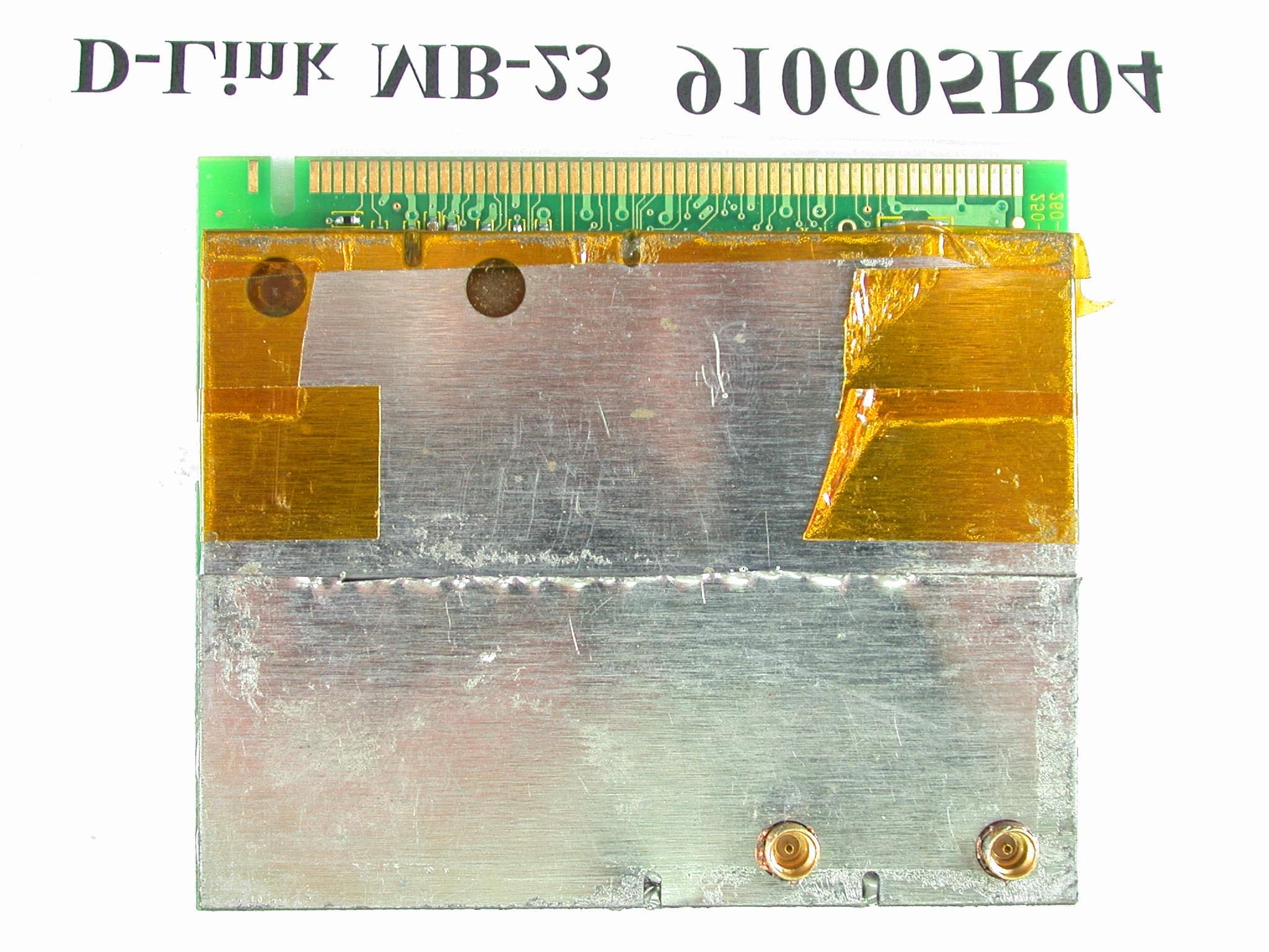
Click to zoom
Application Details
- Equipment Class
- NII - Unlicensed National Information Infrastructure TX
- Date of Grant
- Aug 12, 2002
- Application Purpose
- Original Equipment
- Date of Application
- Aug 12, 2002
- Equipment Note
- Wide Band Mini PCI Module
- Frequency Range
- 5725.00000000 - 5825.00000000
- Company
- D-Link Corporation
- Country
- United States
Documents & Files
Document Text
Text extracted from the exhibit documents filed with the FCC. Open a document above to read the original.
Users Manual
i WMP-A12 5GHz Wireless LAN mini PCI Card User’s Manual First Edition (May, 2002) 6WMPA12...01 Wichtige Sicherheitshinweise 1. Bitte lesen Sie sich diese Hinweise sorgf‰ltig durch. 2. Heben Sie diese Anleitung f ̧r den sp‰tern Gebr uch uf. 3. Vor jedem Reinigen ist d s Ger‰t vom Stromnetz zu trennen. Vervenden Sie keine Fl ̧ssig- oder Aerosolreiniger. Am besten dient ein ngefeuchtetes Tuch zur Reinigung. 4. Um eine Besch‰digung des Ger‰tes zu vermeiden sollten Sie nur Zubehˆrteile verwenden, die vom Hersteller zugel ssen sind. 5. D s Ger‰t is vor Feuchtigkeit zu sch ̧tzen. 6. Bei der Aufstellung des Ger‰tes ist uf sichern St nd zu chten. Ein Kippen oder F llen kˆnnte Verletzungen hervorrufen. Verwenden Sie nur sichere St ndorte und be chten Sie die Aufstellhinweise des Herstellers. 7. Die Bel ̧ftungsˆffnungen dienen zur Luftzirkul tion die d s Ger‰t vor ‹berhitzung sch ̧tzt. Sorgen Sie d f ̧r, d fl diese ÷ffnungen nicht bgedeckt werden. 8. Be chten Sie beim Anschlufl n d s Stromnetz die Anschluflwerte. 9. Die Netz nschluflsteckdose mufl us Gr ̧nden der elektrischen Sicherheit einen Schutzleiterkont kt h ben. 10. Verlegen Sie die Netz nschluflleitung so, d fl niem nd d r ̧ber f llen k nn. Es sollete uch nichts uf der Leitung bgestellt werden. 11. Alle Hinweise und W rnungen die sich m Ger‰ten befinden sind zu be chten. 12. Wird d s Ger‰t ̧ber einen l‰ngeren Zeitr um nicht benutzt, sollten Sie es vom Stromnetz trennen. Somit wird im F lle einer ‹bersp nnung eine Besch‰digung vermieden. 13. Durch die L ̧ftungsˆffnungen d ̧rfen niem ls Gegenst‰nde oder Fl ̧ssigkeiten in d s Ger‰t gel ngen. Dies kˆnnte einen Br nd bzw. Elektrischen Schl g uslˆsen. 14. ÷ffnen Sie niem ls d s Ger‰t. D s Ger‰t d rf us Gr ̧nden der elektrischen Sicherheit nur von uthorisiertem Serviceperson l geˆffnet werden. 15. Wenn folgende Situ tionen uftreten ist d s Ger‰t vom Stromnetz zu trennen und von einer qu lifizierten Servicestelle zu ̧berpr ̧fen: ñ Netzk bel oder Netzstecker sint besch‰digt. b ñ Fl ̧ssigkeit ist in d s Ger‰t eingedrungen. c ñ D s Ger‰t w r Feuchtigkeit usgesetzt. d ñ Wenn d s Ger‰t nicht der Bedienungs nleitung ensprechend funktioniert oder Sie mit Hilfe dieser Anleitung keine Verbesserung erzielen. e ñ D s Ger‰t ist gef llen und/oder d s Geh‰use ist besch‰digt. f ñ Wenn d s Ger‰t deutliche Anzeichen eines Defektes ufweist. 16. Bei Rep r turen d ̧rfen nur rgin lers tzteile bzw. den rgin lteilen entsprechende Teile verwendet werden. Der Eins tz von ungeeigneten Ers tzteilen k nn eine weitere Besch‰digung hervorrufen. 17. Wenden Sie sich mit llen Fr gen die Service und Rep rtur betreffen n Ihren Servicep rtner. Somit stellen Sie die Betriebssicherheit des Ger‰tes sicher. iii 18. Zum Netz nschlufl dieses Ger‰tes ist eine gepr ̧fte Leitung zu verwenden, F ̧r einen Nennstrom bis 6A und einem Ger‰tegewicht grofler 3kg ist eine Leitung nicht leichter ls H05VV-F, 3G, 0.75mm2 einzusetzen Limited Warranty Hardware: D-LINK WARRANTS EACH F ITS HARDWARE PR DUCTS T BE FREE FR M DEFECTS IN W RKMANSHIP AND MATERIALS UNDER N RMAL USE AND SERVICE F R A PERI D C MMENCING N THE DATE F PURCHASE FR M D-LINK R ITS AUTH RIZED RESELLER AND EXTENDING F R THE LENGTH F TIME STIPULATED BY THE AUTH RIZED RESELLER R D-LINK BRANCH FFICE NEAREST T THE PLACE F PURCHASE. THIS WARRANTY APPLIES N THE C NDITI N THAT THE PR DUCT REGISTRATI N CARD IS FILLED UT AND RETURNED T A D-LINK FFICE WITHIN NINETY (90) DAYS F PURCHASE. A LIST F D-LINK FFICES IS PR VIDED AT THE BACK F THIS MANUAL, T GETHER WITH A C PY F THE REGISTRATI N CARD. IF THE PR DUCT PR VES DEFECTIVE WITHIN THE APPLICABLE WARRANTY PERI D, D-LINK WILL PR VIDE REPAIR R REPLACEMENT F THE PR DUCT. D-LINK SHALL HAVE THE S LE DISCRETI N WHETHER T REPAIR R REPLACE, AND REPLACEMENT PR DUCT MAY BE NEW R REC NDITI NED. REPLACEMENT PR DUCT SHALL BE F EQUIVALENT R BETTER SPECIFICATI NS, RELATIVE T THE DEFECTIVE PR DUCT, BUT NEED N T BE IDENTICAL. ANY PR DUCT R PART REPAIRED BY D-LINK PURSUANT T THIS WARRANTY SHALL HAVE A WARRANTY PERI D F N T LESS THAN 90 DAYS, FR M DATE F SUCH REPAIR, IRRESPECTIVE F ANY EARLIER EXPIRATI N F RIGINAL WARRANTY PERI D. WHEN D-LINK PR VIDES REPLACEMENT, THEN THE DEFECTIVE PR DUCT BEC MES THE PR PERTY F D-LINK . WARRANTY SERVICE MAY BE BTAINED BY C NTACTING A D-LINK FFICE WITHIN THE APPLICABLE WARRANTY PERI D, AND REQUESTING A RETURN MATERIAL AUTH RIZATI N (RMA) NUMBER. IF A REGISTRATI N CARD F R THE PR DUCT IN QUESTI N HAS N T BEEN RETURNED T D-LINK , THEN A PR F F PURCHASE (SUCH AS A C PY F THE DATED PURCHASE INV ICE) MUST BE PR VIDED. IF PURCHASERíS CIRCUMSTANCES REQUIRE SPECIAL HANDLING F WARRANTY C RRECTI N, THEN AT THE TIME F REQUESTING RMA NUMBER, PURCHASER MAY ALS PR P SE SPECIAL PR CEDURE AS MAY BE SUITABLE T THE CASE. AFTER AN RMA NUMBER IS ISSUED, THE DEFECTIVE PR DUCT MUST BE PACKAGED SECURELY IN THE RIGINAL R THER SUITABLE SHIPPING PACKAGE T ENSURE THAT IT WILL N T BE DAMAGED IN TRANSIT, AND THE RMA NUMBER MUST BE PR MINENTLY MARKED N THE UTSIDE F THE PACKAGE. THE PACKAGE MUST BE MAILED R THERWISE SHIPPED T D-LINK WITH ALL C STS F MAILING/SHIPPING/INSURANCE PREPAID. D- LINK SHALL NEVER BE RESP NSIBLE F R ANY S FTWARE, FIRMWARE, INF RMATI N, R MEM RY DATA F PURCHASER C NTAINED IN, ST RED N, R INTEGRATED WITH ANY PR DUCT RETURNED T D-LINK PURSUANT T THIS WARRANTY. ANY PACKAGE RETURNED T D-LINK WITH UT AN RMA NUMBER WILL BE REJECTED AND SHIPPED BACK T PURCHASER AT PURCHASERíS EXPENSE, AND D-LINK RESERVES THE RIGHT IN SUCH A CASE T LEVY A REAS NABLE HANDLING CHARGE IN ADDITI N MAILING R SHIPPING C STS. Software: WARRANTY SERVICE F R S FTWARE PR DUCTS MAY BE BTAINED BY C NTACTING A D-LINK FFICE WITHIN THE APPLICABLE WARRANTY PERI D. A LIST F D…
Text truncated - open the document above for the full version.
Cover Letter(s)
D-Link Corporation No.8, Li Hsing Rd VII, Science-based Industrial Park, Hsinchu, Taiwan, R.O.C Tel: +886 3-577-9110 Fax: +886 3-578-1861 Inform Letter Dear Customer, According to FCC’s regulation, the following Declaration of Conformity has to be made by a company located in USA. They are: This device has been confirmed to be in compliance with the requirements of ANSI C63.4 & FCC part 15 regulations. The test result has been shown in the ADT test report with number RF910605R04. And this compliance is subject to the following two conditions: This device may not cause harmful interference and, This device must accept any interference received, including interference that may cause undesired operation. This declaration can be a separate sheet and be sure that the following message will be also included in this declaration: Product name, model name and trade name. Company name, and address of the one who is responsible for this declaration. Name, title, telephone and fax number as well as the signature of the contact person. Thanks for your attention.
Cover Letter(s)
FCC ID: KA22002020012-1 ADT No.910605R04 Modular Approval Request Letter Advance Data Technology Aug. 6, 2002 Dear Application Examiner, D-Link Corporation’s IEEE 802.11a Wide band Mini PCI, FCC ID: KA22002020012-1, would like to have your authorization as a limited modular approval specific to the mobile device such as access point, router and notebook with antenna mounted around the LCD panel. The requirements of Public Notice DA00-1407 have been met and shown on the following statements. 1. “The modular transmitter must have its own RF shielding.”: The radio portion of this module has been shielded, please see exhibition External Photo. 2. “The modular transmitter must have buffered modulation/data inputs.” The EUT has buffered data inputs, it is integrated in chip AR5211. 3. “The modular transmitter must have its own power supply regulation.” The chips IF converter and RF/IF converter which will influence the frequency radiation, have to be 2.5V DC powered. The mini-pci interface provides 3.3VDC, so there are regulators in front of these chips, the part number of this regulator is TK71625SCL. 4. “The modular transmitter must comply with the antenna requirements of section 15.203 and 15.204(C).” The EUT meets the FCC antenna requirements. The spurious emission, unique antenna connector and photo of antennas are shown in the test report. 5. “The modular transmitter must be tested in a stand-alone configuration” The EUT was tested in a stand-alone configuration via a PCI to mini-PCI extender. Please see section Photographs of Test Configuration in the test report, the EUT was plugged in this extender. 6. “The modular transmitter must be labeled with its own FCC ID number.” Please see exhibition Label Sample for the FCC ID of this module. And also in the exhibition Users Manual, there are instructions give to the OEM on how to label the end product. FCC ID: KA22002020012-1 ADT No.910605R04 7. “The modular transmitter must comply with any specific rule or operating requirements applicable to the transmitter and the manufacturer must provide adequate instructions along with the module to explain any such requirements.” The EUT is compliant with all applicable FCC rules. Detail instructions for maintaining compliance are given in the Users Manual. 8. “The modular transmitter must comply with any applicable RF exposure requirements.” The EUT is compliant with all applicable RF exposure requirements. RF Exposure is addressed in the RF exposure exhibition. Please contact me if you have any further questions. Thanks for your attention. Best Regards,
External Photos
Page 1 ANNEX PHOTOGRAPHS OF EUT Page 2 Page 3
External Photos
Page 7 Page 8 Page 9 Page 10
ID Label/Location Info
Te s t ed To Co m ply W i t h CC F S t a n da r ds Model: WMP-A12 IEEE 802.11a Wide band Mini PCI FCC ID: KA22002020012-1 S/N: MAC ID: FOR HOME OR OFFICE USE Made in Taiwan
Internal Photos
Page 4 Page 5 Page 6
Operational Description
FCC ID: KA22002020009-1 ADT No.910605R04 Operational Description The transmitter of the EUT is powered by host equipment. The antenna are Dipole and PIFA antenna. The antenna connector is MMCX connector. Under normal use condition, the user has to keep at least 20cm separation distance between radiator and the body of the user. This device is an IEEE 802.11a Wide band Mini PCI, the maximum data rate could be 108Mbps. For more detailed instruction, please take a look at the user’s manual.
RF Exposure Info
ADT No: 910605R04 1 FCC TEST REPORT REPORT NO.: RF910605R04 MODEL NO.: MB-23 WMP-A12 ACCORDING: FCC Guidelines for Human Exposure IEEE C95.1 APPLICANT:D-LINK CORPORATION ADDRESS: No. 8, Li Hsing Rd VII, Science-Based Industrial Park, Hsinchu, Taiwan, R.O.C. ISSUED BY:Advance Data Technology Corporation LAB LOCATION:47 14th Lin, Chiapau Tsun, Linko, Taipei, Taiwan, R.O.C. 0528 ILAC MRA Lab Code: 200102-0 ADT No: 910605R04 2 RF Exposure Measurement 1. Introduction In this document, we try to prove the safety of radiation harmfulness to the human body for our product. The limit for Maximum Permissible Exposure (MPE) specified in FCC 1.1310 is followed. The Gain of the antenna used in this product is measured in a Fully Anechoic Chamber (FAC) calibrated for antenna measurement in ADT, and also the maximum total power input to the antenna is measured. Through the Friis transmission formula and the maximum gain of the antenna, we can calculate the distance, away from the product, where the limit of MPE is reached. Although the Friis transmission formula is a far field assumption, the calculated result of that is an over-prediction for near field power density. We will take that as the worst case to specify the safety range. 2. RF Exposure Limit According to FCC 1.1310: The criteria listed in the following table shall be used to evaluate the environmental impact of human exposure to radio-frequency (RF) radiation as specified in 1.1307(b) LIMITS FOR MAXIMUM PERMISSIBLE EXPOSURE (MPE) Frequency Range (MHz) Electric Field Strength (V/m) Magnetic Field Strength (A/m) Power Density (mW/cm 2 ) Average Time (minutes) (A)Limits For Occupational / Control Exposures 300-1500......F/3006 1500-100,000......56 (B)Limits For General Population / Uncontrolled Exposure 300-1500......F/15006 1500-100,000......1.030 F = Frequency in MHz ADT No: 910605R04 3 3. Friis Formula Friis transmission formula : Pd = (Pout*G) / (4*pi*r 2 ) where Pd = power density in mW/cm 2 Pout = output power to antenna in mW G = gain of antenna in linear scale Pi = 3.1416 R = distance between observation point and center of the radiator in cm Pd is the limit of MPE, 1 mW/cm 2 . If we know the maximum Gain of the antenna and the total power input to the antenna, through the calculation, we will know the distance r where the MPE limit is reached. Ref. : David K. Cheng, Field and Wave Electromagnetics, Second Edition, Page 640, Eq. (11-133). 4 EUT Operating condition The software provided by Manufacturer enabled the EUT to transmit and receive data at lowest, middle and highest channel individually. 5 Climate Condition The temperature and related humidity: 20 deg. C and 63 % RH 6. Classification This device is not fixed inside the host equipment, it is connected with host through wire. So it is easy to be re-located in the place where at least 20 cm far away from the body of the user. Warning statement to the user for keeping at least 20cm or more separation distance with the antenna should be included in users manual. So, this device is classified as Mobile Device. ADT No: 910605R04 4 7 Test Results 7.1 Antenna Gain The maximum Gain measured in Fully Anechoic Chamber is 3.5dBi or 2.24(numeric). 7.2 Output Power Into Antenna & RF Exposure Distance : Normal Mode: CHANNEL CHANNEL FREQUENCY (MHz) OUTPUT POWER TO ANTENNA (mW) MINIMUM ALLOWABLE DISTANCE ( r ) FROM SKIN (Centi-Meter) 1518039.992.67 4524045.082.83 5526070.963.56 8532073.963.63 9574524.382.08 12580523.282.04 Turbo Mode: CHANNEL CHANNEL FREQUENCY (MHz) OUTPUT POWER TO ANTENNA (mW) MINIMUM ALLOWABLE DISTANCE ( r ) FROM SKIN (Centi-Meter) 1521046.772.89 2525047.862.92 3529071.783.58 4576024.432.09 5580013.271.54 The minimum allowable distance is very close to the enclosure of the antenna. So, the user has no need to worry about the harmfulness of radiation. But it is recommended to always keep, at least, 20 cm separation distance with the antenna.
Test Report
FCC ID: KA22002020012-1 Report No.: RF910605R04 1 Issued: July 25, 2002 FCC TEST REPORT REPORT NO.: RF910605R04 MODEL NO.: MB-23 WMP-A12 RECEIVED: June 17, 2002 TESTED: July 5 ~ July 22, 2002 APPLICANT:D-LINK CORPORATION ADDRESS: No. 8, Li Hsing Rd VII, Science-Based Industrial Park, Hsinchu, Taiwan, R.O.C. ISSUED BY:Advance Data Technology Corporation LAB LOCATION:47 14th Lin, Chiapau Tsun, Linko, Taipei, Taiwan, R.O.C. This test report consists of 228 pages in total. It may be duplicated completely for legal use with the approval of the applicant. It should not be reproduced except in full, without the written approval of our laboratory. The client should not use it to claim product endorsement by CNLA, NVLAP or any government agencies. The test results in the report only apply to the tested sample. 0528 ILAC MRA Lab Code: 200102-0 FCC ID: KA22002020012-1 Report No.: RF910605R04 2 Issued: July 25, 2002 Table of Contents 1CERTIFICATION ........................................................................................... 5 2SUMMARY OF TEST RESULTS................................................................... 6 3GENERAL INFORMATION ........................................................................... 7 3.1GENERAL DESCRIPTION OF EUT ............................................................. 7 3.2DESCRIPTION OF TEST MODES ............................................................... 8 3.3GENERAL DESCRIPTION OF APPLIED STANDARDS............................... 8 3.4DESCRIPTION OF SUPPORT UNITS.......................................................... 9 4TEST TYPES AND RESULTS .................................................................... 10 4.1CONDUCTED EMISSION MEASUREMENT .............................................. 10 4.1.1LIMITS OF CONDUCTED EMISSION MEASUREMENT ........................... 10 4.1.2TEST INSTRUMENTS ................................................................................ 10 4.1.3TEST PROCEDURES..................................................................................11 4.1.4TEST SETUP ...............................................................................................11 4.1.5EUT OPERATING CONDITIONS................................................................ 12 4.1.6TEST RESULTS (A) (TRANSMITTING)...................................................... 13 4.1.7TEST RESULTS (B) (TRANSMITTING)...................................................... 17 4.1.8TEST RESULTS (C) (TRANSMITTING)...................................................... 21 4.1.9TEST RESULTS (A) (RECEIVING) ............................................................. 25 4.1.10 TEST RESULTS (B) (RECEIVING) ............................................................. 29 4.1.11 TEST RESULTS (C) (RECEIVING)............................................................. 33 4.2RADIATED EMISSION MEASUREMENT ................................................... 37 4.2.1LIMITS OF RADIATED EMISSION MEASUREMENT ................................ 37 4.2.2TEST INSTRUMENTS ................................................................................ 38 4.2.3TEST PROCEDURES................................................................................. 39 4.2.4TEST SETUP .............................................................................................. 40 4.2.5EUT OPERATING CONDITIONS................................................................ 40 4.2.6TEST RESULTS (A) (TRANSMITTING)...................................................... 41 4.2.7TEST RESULTS (B) (TRANSMITTING)...................................................... 56 4.2.8TEST RESULTS (C) (TRANSMITTING)...................................................... 71 4.2.9TEST RESULTS (A) (RECEIVING) ............................................................. 86 4.2.10 TEST RESULTS (B) (RECEIVING) ........................................................... 101 4.2.11 TEST RESULTS (C) (RECEIVING)............................................................116 4.3PEAK TRANSMIT POWER MEASUREMENT .......................................... 131 4.3.1LIMITS OF PEAK TRANSMIT POWER MEASUREMENT ....................... 131 4.3.2TEST INSTRUMENTS .............................................................................. 131 FCC ID: KA22002020012-1 Report No.: RF910605R04 3 Issued: July 25, 2002 4.3.3TEST PROCEDURE ................................................................................. 132 4.3.4TEST SETUP ............................................................................................ 132 4.3.5EUT OPERATING CONDITIONS.............................................................. 132 4.3.6TEST RESULTS........................................................................................ 133 4.4PEAK POWER EXCURSION MEASUREMENT ....................................... 146 4.4.1LIMITS OF PEAK POWER EXCURSION MEASUREMENT..................... 146 4.4.2TEST INSTRUMENTS .............................................................................. 146 4.4.3TEST PROCEDURE ................................................................................. 147 4.4.4TEST SETUP ............................................................................................ 147 4.4.5EUT OPERATING CONDITIONS.............................................................. 147 4.4.6TEST RESULTS........................................................................................ 148 4.5PEAK POWER SPECTRAL DENSITY MEASUREMENT ......................... 161 4.5.1LIMITS OF PEAK POWER SPECTRAL DENSITY MEASUREMENT ...... 161 4.5.2TEST INSTRUMENTS .............................................................................. 161 4.5.3TEST PROCEDURES............................................................................... 162 4.5.4TEST SETUP ............................................................................................ 162 4.5.5EUT OPERATING CONDITIONS........................................…
Text truncated - open the document above for the full version.
Test Report
FCC ID: KA22002020012-1 Report No.: RF910605R04 151 Issued: July 25, 2002 CHANNEL 5 FCC ID: KA22002020012-1 Report No.: RF910605R04 152 Issued: July 25, 2002 CHANNEL 8 FCC ID: KA22002020012-1 Report No.: RF910605R04 153 Issued: July 25, 2002 CHANNEL 9 FCC ID: KA22002020012-1 Report No.: RF910605R04 154 Issued: July 25, 2002 CHANNEL 12 FCC ID: KA22002020012-1 Report No.: RF910605R04 155 Issued: July 25, 2002 EUT IEEE 802.11a Wide band Mini PCI MODEL MB-23 MODE Turbo INPUT POWER (SYSTEM) 120Vac, 60 Hz ENVIRONMENTAL CONDITIONS 29 deg. C, 54%RH, 1005 hPa TESTED BY Steven Lu CHANNEL CHANNEL FREQUENCY (MHz) PEAK POWER EXCURSION (dBm) PEAK to AV E R AG E EXCURSION LIMIT (dB) PASS/FAIL 152108.6413PASS 252508.8813PASS 352908.2913PASS 457608.4513PASS 558008.6313PASS FCC ID: KA22002020012-1 Report No.: RF910605R04 156 Issued: July 25, 2002 CHANNEL 1 FCC ID: KA22002020012-1 Report No.: RF910605R04 157 Issued: July 25, 2002 CHANNEL 2 FCC ID: KA22002020012-1 Report No.: RF910605R04 158 Issued: July 25, 2002 CHANNEL 3 FCC ID: KA22002020012-1 Report No.: RF910605R04 159 Issued: July 25, 2002 CHANNEL 4 FCC ID: KA22002020012-1 Report No.: RF910605R04 160 Issued: July 25, 2002 CHANNEL 5 FCC ID: KA22002020012-1 Report No.: RF910605R04 161 Issued: July 25, 2002 4.5 PEAK POWER SPECTRAL DENSITY MEASUREMENT 4.5.1 LIMITS OF PEAK POWER SPECTRAL DENSITY MEASUREMENT Frequency BandLimit 5.15 – 5.25 GHz4dBm 5.25 – 5.35 GHz11dBm 5.725 – 5.825 GHz17dBm 4.5.2 TEST INSTRUMENTS Description & ManufacturerModel No.Serial No.Calibrated Until ROHDE&SCHWARZ SPECTRUM ANALYZER FSEK30100049July 24, 2003 NOTE: 1. The measurement uncertainty is less than +/- 2.6dB, which is calculated as per the NAMAS document NIS81. 2. The calibration interval of the above test instruments is 12 months and the calibrations are traceable to NML/ROC and NIST/USA. FCC ID: KA22002020012-1 Report No.: RF910605R04 162 Issued: July 25, 2002 4.5.3 TEST PROCEDURES 1. The transmitter output was connected to the spectrum analyzer. 2. Set RBW=1MHz, VBW=3MHz. The PPSD can be found. 4.5.4 TEST SETUP 4.5.5 EUT OPERATING CONDITIONS Same as 4.3.5 EUT SPECTRUM ANALYZER FCC ID: KA22002020012-1 Report No.: RF910605R04 163 Issued: July 25, 2002 4.5.6 TEST RESULTS EUT IEEE 802.11a Wide band Mini PCI MODEL MB-23 MODE Normal INPUT POWER (SYSTEM) 120Vac, 60 Hz ENVIRONMENTAL CONDITIONS 29 deg. C, 54%RH, 1005 hPa TESTED BY Steven Lu CHANNEL NUMBER CHANNEL FREQUENCY (MHz ) RF POWER LEVEL IN 1 MHz BW (dBm) MAXIMUM LIMIT (dBm) PASS/FAIL 15180-0.904PASS 45240-0.674PASS 552602.5811PASS 853202.8611PASS 95745-1.2717PASS 1258050.1317PASS FCC ID: KA22002020012-1 Report No.: RF910605R04 164 Issued: July 25, 2002 CHANNEL 1 FCC ID: KA22002020012-1 Report No.: RF910605R04 165 Issued: July 25, 2002 CHANNEL 4 FCC ID: KA22002020012-1 Report No.: RF910605R04 166 Issued: July 25, 2002 CHANNEL 5 FCC ID: KA22002020012-1 Report No.: RF910605R04 167 Issued: July 25, 2002 CHANNEL 8 FCC ID: KA22002020012-1 Report No.: RF910605R04 168 Issued: July 25, 2002 CHANNEL 9 FCC ID: KA22002020012-1 Report No.: RF910605R04 169 Issued: July 25, 2002 CHANNEL 12 FCC ID: KA22002020012-1 Report No.: RF910605R04 170 Issued: July 25, 2002 EUT IEEE 802.11a Wide band Mini PCI MODEL MB-23 MODE Turbo INPUT POWER (SYSTEM) 120Vac, 60 Hz ENVIRONMENTAL CONDITIONS 29 deg. C, 54%RH, 1005 hPa TESTED BY Steven Lu CHANNEL NUMBER CHANNEL FREQUENCY (MHz ) RF POWER LEVEL IN 1 MHz BW (dBm) MAXIMUM LIMIT (dBm) PASS/FAIL 15210-1.774PASS 25250-2.604PASS 35290-0.3311PASS 45760-3.2517PASS 55800-5.7717PASS FCC ID: KA22002020012-1 Report No.: RF910605R04 171 Issued: July 25, 2002 CHANNEL 1 FCC ID: KA22002020012-1 Report No.: RF910605R04 172 Issued: July 25, 2002 CHANNEL 2 FCC ID: KA22002020012-1 Report No.: RF910605R04 173 Issued: July 25, 2002 CHANNEL 3 FCC ID: KA22002020012-1 Report No.: RF910605R04 174 Issued: July 25, 2002 CHANNEL 4 FCC ID: KA22002020012-1 Report No.: RF910605R04 175 Issued: July 25, 2002 CHANNEL 5 FCC ID: KA22002020012-1 Report No.: RF910605R04 176 Issued: July 25, 2002 4.6 EFFECTIVE ISOTROPIC RADIATED POWER SPURIOUS EMISSIONS MEASUREMENT 4.6.1 LIMITS OF EFFECTIVE ISOTROPIC RADIATED POWER SPURIOUS EMISSIONS MEASUREMENT (1) For transmitters operating in the 5.15 – 5.25 GHz band: All emissions outside of the 5.15 – 5.25 GHz band shall not exceed an EIRP of –27dBm/MHz. (2) For transmitters operating in the 5.25 – 5.35 GHz band: All emissions outside of the 5.25 – 5.35 GHz band shall not exceed an EIRP of –27dBm/MHz. (3) For transmitters operating in the 5.725 – 5.825 GHz band: All emissions operating within the frequency range from the band edge 10 MHz above or below the band edge shall not exceed an EIRP of –17dBm/MHz; for frequencies 10 MHz or greater above or below the band edge shall not exceed an EIRP of –27dBm/MHz. 4.6.2 TEST INSTRUMENTS DESCRIPTION & MANUFACTURER MODEL NO.SERIAL NO. CALIBRATED UNTIL * ROHDE & SCHWARZ Spectrum Analyzer FSEK30100049July 24, 2003 ROHDE & SCHWARZ Signal Generator 68247B984703May 31, 2003 * EMCO Horn Antenna31155623May 23, 2003 * EMCO Horn Antenna31155619May 22, 2003 MITEQ PreamplifierAMF-4D-0051692677NA MITEQ PreamplifierAFS33-18002690751NA Broadband Horn AntennaBBHA 9170147May 30, 2003 Broadband Horn AntennaBBHA 9170148May 31, 2003 NOTE: 1. The measurement uncertainty is less than +/- 2.6dB, which is calculated as per the NAMAS document NIS81. 2. The calibration interval of the above test instruments is 12 months and the calibrations are traceable to NML/ROC and NIST/USA. FCC ID: KA22002020012-1 Report No.: RF910605R04 177 Issued: July 25, 2002 4.6.3 TEST PROCEDURE 1. The EUT was placed on the top of a rotating table 1.5 meters above the ground. 2. The table was rotated 360 degrees to determine the position of the highest radiation. 3. The EUT was set 1.5 meters away from the receiving antenna, which was mounted on antenna tower and its position at 1.5 m above the ground. 4. For each suspected emission, the EUT was arranged to its worst case and the rotatable table was turned from 0…
Text truncated - open the document above for the full version.
Test Report
FCC ID: KA22002020012-1 Report No.: RF910605R04 191 Issued: July 25, 2002 EUT IEEE 802.11a Wide band Mini PCI MODEL MB-23 MODENormal Mode CHANNEL 4 FREQUENCY RANGE Above 1000 MHz DETECTOR FUNCTION Peak(PK) ENVIRONMENTAL CONDITIONS 25 deg. C, 70%RH, 1050 hPa INPUT POWER (SYSTEM) 120Vac, 60 Hz TESTED BY Steven Lu EIRP SPURIOUS EMISSION LEVEL Frequency (MHz) Antenna Polarization Level (dBm) Limit (dBm) MarginRemark 10477.70H-33.9-27.0-6.9 10482.30V-36.4-27.0-9.4 15720.60----NOTE 20963.51----NOTE 26142.08H-52.4-27.0-25.4 26190.18V-51.1-27.0-24.1 NOTE: The emissions appearing in the restricted Bands shall not exceed the general limits of 15.209. FCC ID: KA22002020012-1 Report No.: RF910605R04 192 Issued: July 25, 2002 EUT IEEE 802.11a Wide band Mini PCI MODEL MB-23 MODENormal Mode CHANNEL 5 FREQUENCY RANGE Above 1000 MHz DETECTOR FUNCTION Peak(PK) ENVIRONMENTAL CONDITIONS 25 deg. C, 70%RH, 1050 hPa INPUT POWER (SYSTEM) 120Vac, 60 Hz TESTED BY Steven Lu EIRP SPURIOUS EMISSION LEVEL Frequency (MHz) Antenna Polarization Level (dBm) Limit (dBm) MarginRemark 10520.50H-30.8-27.0-3.8 10521.50V-30.8-27.0-3.8 15779.00----NOTE 21036.29----NOTE 26339.68H-53.6-27.0-26.6 26381.36V-51.4-27.0-24.4 NOTE: The emissions appearing in the restricted Bands shall not exceed the general limits of 15.209. FCC ID: KA22002020012-1 Report No.: RF910605R04 193 Issued: July 25, 2002 EUT IEEE 802.11a Wide band Mini PCI MODEL MB-23 MODENormal Mode CHANNEL 8 FREQUENCY RANGE Above 1000 MHz DETECTOR FUNCTION Peak(PK) ENVIRONMENTAL CONDITIONS 25 deg. C, 70%RH, 1050 hPa INPUT POWER (SYSTEM) 120Vac, 60 Hz TESTED BY Steven Lu EIRP SPURIOUS EMISSION LEVEL Frequency (MHz) Antenna Polarization Level (dBm) Limit (dBm) MarginRemark 5350.00----NOTE 10639.10----NOTE 15961.00----NOTE 21276.89----NOTE 26522.85H-50.7-27.0-23.7 26624.05V-49.2-27.0-22.2 NOTE: The emissions appearing in the restricted Bands shall not exceed the general limits of 15.209. FCC ID: KA22002020012-1 Report No.: RF910605R04 194 Issued: July 25, 2002 EUT IEEE 802.11a Wide band Mini PCI MODEL MB-23 MODENormal Mode CHANNEL 9 FREQUENCY RANGE Above 1000 MHz DETECTOR FUNCTION Peak(PK) ENVIRONMENTAL CONDITIONS 25 deg. C, 70%RH, 1050 hPa INPUT POWER (SYSTEM) 120Vac, 60 Hz TESTED BY Steven Lu EIRP SPURIOUS EMISSION LEVEL Frequency (MHz) Antenna Polarization Level (dBm) Limit (dBm) MarginRemark 5715.00V-34.97-27.0-7.97 5725.00V-23.54-17.0-6.54 11483.29----NOTE 17230.39H-47.2-27.0-20.2 17240.21V-43.9-27.0-16.9 22979.30----NOTE NOTE: The emissions appearing in the restricted Bands shall not exceed the general limits of 15.209. FCC ID: KA22002020012-1 Report No.: RF910605R04 195 Issued: July 25, 2002 EUT IEEE 802.11a Wide band Mini PCI MODEL MB-23 MODENormal Mode CHANNEL 12 FREQUENCY RANGE Above 1000 MHz DETECTOR FUNCTION Peak(PK) ENVIRONMENTAL CONDITIONS 25 deg. C, 70%RH, 1050 hPa INPUT POWER (SYSTEM) 120Vac, 60 Hz TESTED BY Steven Lu EIRP SPURIOUS EMISSION LEVEL Frequency (MHz) Antenna Polarization Level (dBm) Limit (dBm) MarginRemark 5825.00V-23.82-17.0-6.82 5835.00V-36.60-27.0-9.60 11604.69----NOTE 17401.37V-40.9-27.0-13.9 17407.59H-46.0-27.0-19.0 23240.14V-55.3-27.0-28.3 23272.20H-56.0-27.0-29.0 NOTE: The emissions appearing in the restricted Bands shall not exceed the general limits of 15.209. FCC ID: KA22002020012-1 Report No.: RF910605R04 196 Issued: July 25, 2002 EUT IEEE 802.11a Wide band Mini PCI MODEL MB-23 MODETurbo Mode CHANNEL 1 FREQUENCY RANGE Above 1000 MHz DETECTOR FUNCTION Peak(PK) ENVIRONMENTAL CONDITIONS 25 deg. C, 70%RH, 1050 hPa INPUT POWER (SYSTEM) 120Vac, 60 Hz TESTED BY Steven Lu EIRP SPURIOUS EMISSION LEVEL Frequency (MHz) Antenna Polarization Level (dBm) Limit (d…
Text truncated - open the document above for the full version.
Contact Information
Applicant
Brett Adair(General Counsel)
Technical Contact
Advance Data Technology CorporationVivi Wang
[email protected]+886 3 327 0910
13-1, Lane 19, WenShan 3rd St · Taoyuan · Taiwan
Test Firm
Bureau Veritas CPS (H.K.) Ltd. Taoyuan BranchRichard Chen
Technical Specifications
| # | Rule Parts | Frequency Range | Power Output |
|---|---|---|---|
| 3 | 15E | 5.72 GHz - 5.83 GHz | 24.00 mW |
Other Applications from D-Link Corporation
KA2CS6530A1
Sep 08, 20262K Pan & Tilt Outdoor Wi-Fi Camera
Equipment Class
DTS - Digital Transmission System
KA2CS6012A1
Jul 07, 20262K Fixed Indoor Cloud Camera, 2K Fixed Indoor Wi-Fi Camera
Equipment Class
DTS - Digital Transmission SystemKA2AE65UA1
Mar 02, 2026Wi-Fi 7 BE6500 USB 3.0 Dongle
Equipment Class
NII - Unlicensed National Information Infrastructure TXKA2APE9560A1
Nov 17, 2025BE9500 Celling mount Access Point
Equipment Class
6ID - 15E 6 GHz Low Power Indoor Access PointKA2AX9UA1
Dec 04, 2024AX900 Wi-Fi 6 USB Adapter, Wi-Fi 6 AX900 USB 2.0 Dongle
Equipment Class
DSS - Part 15 Spread Spectrum Transmitter