KA22002090030-1High Speed 2.4GHz Wireless Cardbus Card
D-Link Corporation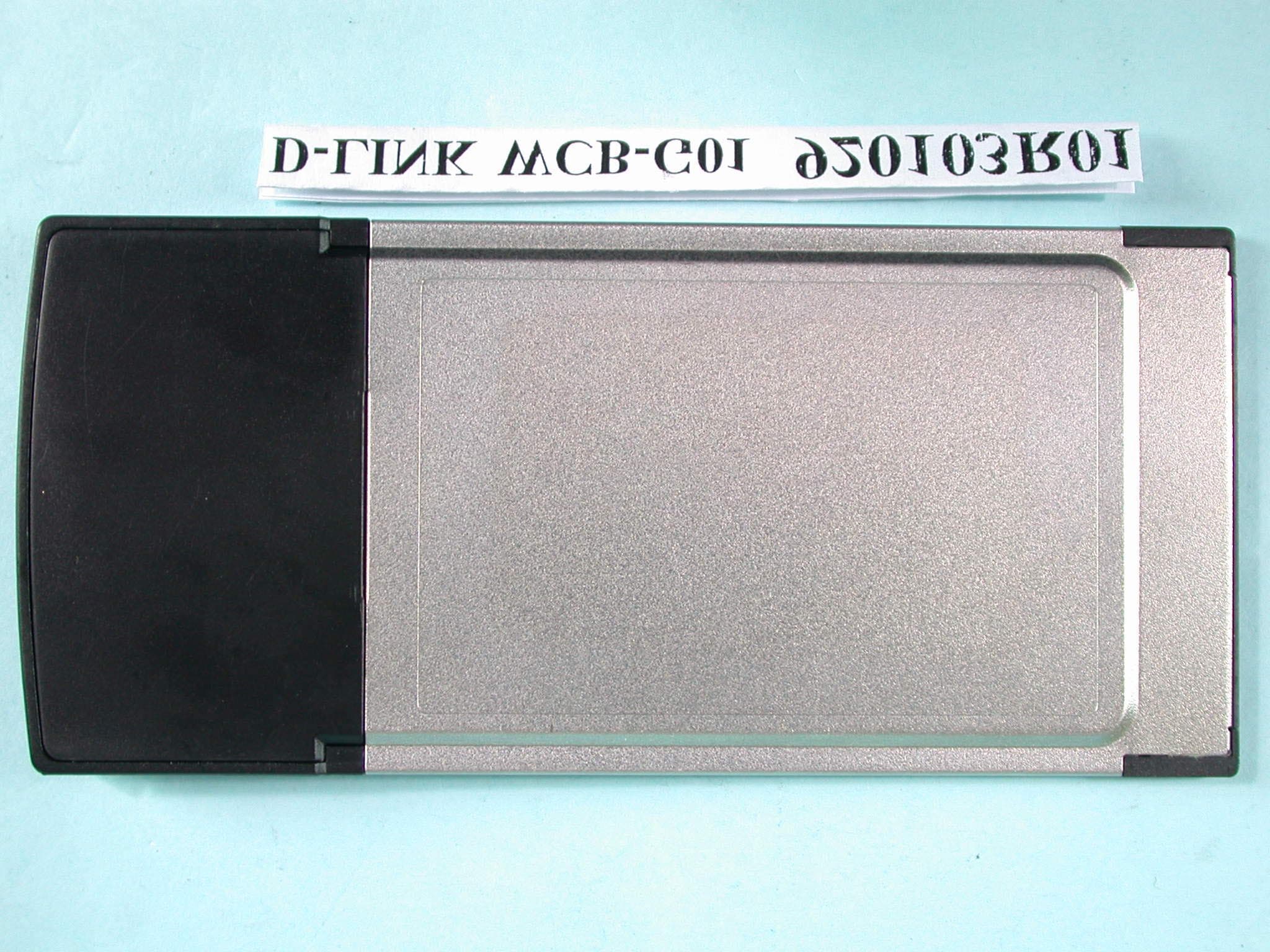
Click to zoom
Application Details
- Equipment Class
- DTS - Digital Transmission System
- Date of Grant
- Feb 24, 2003
- Application Purpose
- Original Equipment
- Date of Application
- Feb 24, 2003
- Equipment Note
- High Speed 2.4GHz Wireless Cardbus Card
- Frequency Range
- 2412.00000000 - 2462.00000000
- Company
- D-Link Corporation
- Country
- United States
Documents & Files
Document Text
Text extracted from the exhibit documents filed with the FCC. Open a document above to read the original.
Users Manual
Manual Building Networks for People 2.4GHz up to 54Mbps DWL-G650 D-Link AirPlusXTREMEG TM Wireless Cardbus Adapter 2 Contents Package Contents..........................................................................................3 Introduction......................................................................................................4 Wireless Basics..............................................................................................7 Getting Started..............................................................................................11 Using the Configuration Utility....................................................................14 Networking Basics.......................................................................................21 Troubleshooting............................................................................................34 Technical Specifications..............................................................................39 Contacting Technical Support.....................................................................41 Warranty and Registration..........................................................................42 3 Contents of Package: D-Link AirPlusXtremeG DWL-G650 2.4 GHz - 54Mbps Wireless Cardbus Adapter Manual and Warranty on CD Quick Installation Guide Package Contents If any of the above items are missing, please contact your reseller. System Requirements for Configuration: n n n An 802.11g Access Point (for optimal performance), or an 802.11b Access Point (e.g., DWL-900AP) for Access Point mode, or another 802.11g wireless adapter (DWL-G650) for laptops or an 802.11b wireless adapter (e.g., DWL-520 for desktops) for Peer-to-Peer n At least 32 MB of memory and a 300 MHz processor n Windows XP, Windows 2000, Windows Me, or Windows 98SE n A laptop or notebook computer with an available 32-bit Cardbus slot n TM mode. 4 Introduction The D-Link AirPlusXtremeG DWL-G650 Wireless Cardbus Adapter is an enhanced 802.11g high-performance, wireless adapter that supports high-speed wireless networking at home, at work or in public places. Unlike most network cards, the DWL-G650 provides speeds of up to 54 Mbps (compared to the standard 11 Mbps) when used with other D-Link AirXtremeG products. This means that you do not need to change your entire network to maintain connectivity. You may sacrifice some of 802.11g’s speed when you mix 802.11b and 802.11g devices, but you will not lose the ability to communicate when you incorporate the 802.11g standard into your 802.11b network. You may choose to slowly change your network by replacing the 802.11b devices with 802.11g devices gradually. In addition to offering faster data transfer speeds when used with other 802.11g products, the DWL-G650 has the newest, strongest, most advanced security features available today. For home users that will not incorporate a radius server in their network, the security for the DWL-G650, used in conjunction with other 802.11g products, will be much stronger than ever before. No longer will you have to manually input a new WEP key frequently to ensure security, with the DWL-G650, you will automatically receive a new key every time you connect, vastly increasing the safety of your communications. TM 5 The DWL-G650 is compatible with existing 802.11b devices such as the D-Link Air, AirPlus and AirPro family of products including the DWL-520, DWL-520+ and the DWL-AB520 Wireless PCI Adapter, the DI-714 Wireless Router/Access Point and the DWL-120 Wireless USB Adapter. (When used with 802.11b devices, the DWL-G650 will reach speeds at up to 11Mbps.) It is an ideal way to connect one laptop computer to a Wireless Local Area Network (WLAN.) After completing the steps outlined in the Quick Installation Guide (included in the package) you will have the ability to share information and resources, such as files and printers, and take full advantage of a “connected” environment for work or play! The DWL-G650 includes software drivers for the most popular Microsoft Windows operating systems (Windows XP, Windows 2000, Windows Me, Windows 98) and can be integrated into a larger network, running, in either Peer-to-Peer mode (without an Access Point) or mode (with an Access Point.) Please take a look at our Getting Started section in this manual to see examples of typical network setups using the DWL-G650 in both Access Point and Peer-to-Peer modes. This manual provides a quick introduction to wireless technology and its application as it relates to networking. Take a moment to read through this manual and get acquainted with wireless technology. Access Point 6 LEDS LED stands for Light-Emitting Diode. The DWL-G650 has the following LEDs: LEDLED Activity A blinking light indicates network activityActivity Operates in the 2.4GHz frequency range Features n Backwards compatible with the 802.11b standard to provide a wireless data rate of up to 11Mbps D-Link AirPlusXtremeG DWL-G650 wireless data rate of up to 54Mbpsn n n User-friendly configuration and diagnostic utilities n Utilizes OFDM technology (Orthogonal Frequency Division Multiplexing) 7 D-Link wireless products are based on industry standards to provide easy-to- use and compatible high-speed wireless connectivity within your home, business or public access wireless networks. Strictly adhering to the IEEE standard, the D-Link wireless family of products will allow you to securely access the data you want, when and where you want it. You will be able to enjoy the freedom that wireless networking delivers. A wireless local area network (WLAN) is a cellular computer network that transmits and receives data with radio signals instead of wires. Wireless LANs are used increasingly in both home and office environments, and public areas such as airports, coffee shops and universities. Innovative ways to utilize WLAN technology are helping people to work and communicate more efficiently. Increased mobility and the absence …
Text truncated - open the document above for the full version.
Users Manual
21 Please follow all the instructions in this window: Networking Basics Click Next In the following window, select the best description of your computer. If your computer connects to the internet through a gateway/router, select the second option as shown. Click Next 22 Enter a Computer description and a Computer name (optional.) Networking Basics Click Next Enter a Workgroup name. All computers on your network should have the same Workgroup name. Click Next 23 Please wait while the Network Setup Wizard applies the changes. Networking Basics When the changes are complete, click Next. Please wait while the Network Setup Wizard configures the computer. This may take a few minutes. 24 Networking Basics In the window below, select the option that fits your needs. In this example, Create a Network Setup Disk has been selected. You will run this disk on each of the computers on your network. Click Next. Insert a disk into the Floppy Disk Drive, in this case drive A. Click Next 25 Networking Basics Please read the information under Here’s how in the screen below. After you complete the Network Setup Wizard you will use the Network Setup Disk to run the Network Setup Wizard once on each of the computers on your network. To continue click Next. 26 Networking Basics Please read the information on this screen, then click Finish to complete the Network Setup Wizard. The new settings will take effect when you restart the computer. Click Yes to restart the computer. You have completed configuring this computer. Next, you will need to run the Network Setup Disk on all the other computers on your network. After run- ning the Network Setup Disk on all your computers, your new wireless net- work will be ready to use. 27 n Networking Basics Naming your Computer To name your computer, please follow these directions:In Windows XP: Click Start (in the lower left corner of the screen) Right-click on My Computer Select Properties and click n n n n n Select the Computer Name Tab in the System Properties window. You may enter a Com- puter Description if you wish; this field is optional. To rename the computer and join a domain, Click Change. 28 Networking Basics Naming your Computer Checking the IP Address in Windows XP The wireless adapter-equipped computers in your network must be in the same IP Ad- dress range (see Getting Started in this manual for a definition of IP Address Range.) To check on the IP Address of the adapter, please do the following: Right-click on the Local Area Connection icon in the task bar Click on Status n n n Click OK All computers on your network must have the same Workgroup name. n Select Workgroup and enter the name of the Workgroup n nIn this window, enter the Computer name 29 Networking Basics Checking the IP Address in Windows XP This window will appear. Click the Support tab Click Close n n Assigning a Static IP Address in Windows XP/2000 Note: Residential Gateways/Broadband Routers will automatically assign IP Ad- dresses to the computers on the network, using DHCP (Dynamic Host Configura- tion Protocol) technology. If you are using a DHCP-capable Gateway/Router you will not need to assign Static IP Addresses. If you are not using a DHCP capable Gateway/Router, or you need to assign a Static IP Address, please follow these instructions: n n Go to Start Double-click on Control Panel 30 Networking Basics Assigning a Static IP Address in Windows XP/2000 nDouble-click on Network Connections n n Double-click on Properties Right-click on Local Area Connections 31 Networking Basics Assigning a Static IP Address in Windows XP/2000 You have completed the assignment of a Static IP Address. (You do not need to assign a Static IP Address if you have a DHCP-capable Gateway/Router.) Click on Internet Protocol (TCP/IP) Click Properties n n IP Address: e.g., 192.168.0.2 Subnet Mask: 255.255.255.0 Default Gateway: Enter the LAN IP address of the wireless router. (D-Link wireless routers have a LAN IP address of 192.168.0.1) In the window below, select Use the following IP address. Input your IP address and subnet mask. (The IP Addresses on your network must be within the same range. For example, if one computer has an IP Address of 192.168.0.2, the other computers should have IP Addresses that are sequential, like 192.168.0.3 and 192.168.0.4. The subnet mask must be the same for all the computers on the network.) n Click OK Select Use the following DNS server address. Enter the LAN IP address of the Wireless Router. (D-Link wireless routers have a LAN IP address of 192.168.0.1) n n 32 Networking Basics Checking the Wireless Connection by Pinging in Windows XP and 2000 Checking the Wireless Connection by Pinging in Windows ME and 98SE Go to Start > Run > type cmd. A window similar to this one will appear. Type ping xxx.xxx.xxx.xxx, where xxx is the IP Address of the Wireless Router or Access Point. A good wireless connection will show four replies from the Wireless Router or access point, as shown. Go to Start > Run > type command. A window similar to this will appear. Type ping xxx.xxx.xxx.xxx where xxx is the IP Address of the Wireless Router or Access Point. A good wireless connection will show four replies from the wireless router or access point, as shown. n n 33 1. Check that the drivers for the DWL-G650 are installed properly. Click Device Manager n Select the Hardware Tab n Troubleshooting This chapter provides solutions to problems that can occur during the installation and operation of the DWL-G650. Read the following descriptions if you are having problems. (The examples below are illustrated in Windows XP. If you have a different operating system, the screenshots on your computer will look similar to the following examples.) nGo to Start > My Computer > Properties 34 Troubleshooting n n n n Double-click on Network Adapters Right-click on D-Link DWL-G650 Wireless Cardbus Adapter Select Properties to check that the drivers are in- stalled properly Click OK n Look under Device Status to …
Text truncated - open the document above for the full version.
Cover Letter(s)
American Telecommunications Certification Body Inc. 6731 Whittier Ave, McLean, VA 22101 January 28, 2003 RE: D-Link Corporation FCC ID: KA22002090030 I have a few comments on this Application. 1.) Please review Manual. I cannot find any references to how end users can limit their RF exposure. [See last page of Manual] 2.) Block diagram shows signal paths, but not frequencies of any oscillators per 2.1033(a)(5). 3.) Device appears larger than the palm of the hand. Therefore, two part label language of 15.19(a)(3) is required to appear on the device. If placement in the Manual is still desired, please justify. 4.) Three differing physical configurations of this device appear in the External Photographs. Please explain what the differences are, and explain how they are different. If the “nose” of any one card is shorter than the others it may place the antenna elements closer to the body. It would then be reasonable to expect this to create a greater SAR. Are we looking at the “worst case” configuration? Please justify your choice. 5.) Please review the DofC form. D-Link has a large presence in US. Therefore it is my belief that a US contact is available. William H. Graff President and Examining Engineer mailto: [email protected] The items indicated above must be submitted before processing can continue on the above referenced application. Failure to provide the requested information may result in application termination. Correspondence should be considered part of the permanent submission and may be viewed from the Internet after a Grant of Equipment Authorization is issued. Please do not respond to this correspondence using the email reply button. In order for your response to be processed expeditiously, you must submit your documents through the AmericanTCB.com website. Also, please note that partial responses increase processing time and should not be submitted. Any questions about the content of this correspondence should be directed to the sender.
External Photos
Page 1 ANNEX PHOTOGRAPHS OF EUT Page 2 Page 3
External Photos
Page 4 Page 5 Page 6
ID Label/Location Info
FCC ID LABEL LOCATION This device complies with Part 15 of the FCC Rules. Operation is subject to the following two conditions: Node ID: S/N: FCC ID: KA22002090030-1 DWL-G650 (1) this device may not cause harmful interference and (2) this device must accept any interference received, including interference that may cause undesired operation. Node ID: S/N: FCC ID: KA22002090030-1 DWL-G650 Tested To Comply With FCC Standards FOR HOME OR OFFICE USE (1) this device may not cause harmful interference and (2) this device must accept any interference received, including interference that may cause undesired operation. Tested To Comply With FCC Standards FOR HOME OR OFFICE USE (1) this device may not cause harmful interference and (2) this device must accept any interference received, including interference that may cause undesired operation. This device complies with Part 15 of the FCC Rules. Operation is subject to the following two conditions: Node ID: S/N: FCC ID: KA22002090030-1 DWL-G650 Node ID: S/N: FCC ID: KA22002090030-1 DWL-G650 Tested To Comply With FCC Standards FOR HOME OR OFFICE USE
ID Label/Location Info
This device complies with Part 15 of the FCC Rules. Operation is subject to the following two conditions: Node ID: S/N: FCC ID: KA22002090030-1 DWL-G650 (1) this device may not cause harmful interference and (2) this device must accept any interference received, including interference that may cause undesired operation. Node ID: S/N: FCC ID: KA22002090030-1 DWL-G650 Tested To Comply With FCC Standards FOR HOME OR OFFICE USE (1) this device may not cause harmful interference and (2) this device must accept any interference received, including interference that may cause undesired operation. Tested To Comply With FCC Standards FOR HOME OR OFFICE USE (1) this device may not cause harmful interference and (2) this device must accept any interference received, including interference that may cause undesired operation. This device complies with Part 15 of the FCC Rules. Operation is subject to the following two conditions: Node ID: S/N: FCC ID: KA22002090030-1 DWL-G650 Node ID: S/N: FCC ID: KA22002090030-1 DWL-G650 Tested To Comply With FCC Standards FOR HOME OR OFFICE USE
Internal Photos
Page 7 Page 8 Page 9
Operational Description
FCC ID: KA22002090030-1 ADT No.920103R01 Operational Description This device is a High-Speed 2.4GHz Wireless Cardbus Card which operates in 2.4GHz band, the maximum data rate could be up to 54Mbps which OFDM technique will be applied, and also, a turbo mode was provided to this EUT at freq. 2437MHz. If the signal to noise radio is too poor which could not support 54Mbps, the 11Mbps data rate with CCK technique will be applied. The transmitter of the EUT is powered by host equipment via a PCMCIA interface. The antenna is PCB printed antenna. There is no antenna connector. The other instruction, please have a look at the users manual.
RF Exposure Info
FCC ID: KA22002090030-1 Report No.: SA920103R01 1 Issued: Jan. 17, 2003 SAR TEST REPORT REPORT NO.: SA920103R01 MODEL NO.: DWL-G650 WCB-G01J WCB-G01 RECEIVED: Jan. 03, 2003 TESTED: Jan. 16, 2003 APPLICANT: D-Link Corporation ADDRESS:No. 8, Li Hsing Rd VII, Science-based Industrial Park, Hsinchu, Taiwan, R.O.C. ISSUED BY:Advance Data Technology Corporation LAB LOCATION:47 14th Lin, Chiapau Tsun, Linko, Taipei, Taiwan, R.O.C. This test report consists of 14 pages in total except Appendix. It may be duplicated completely for legal use with the approval of the applicant. It should not be reproduced except in full, without the written approval of our laboratory. The client should not use it to claim product endorsement by CNLA, NVLAP or any government agencies. The test results in the report only apply to the tested sample. FCC ID: KA22002090030-1 Report No.: SA920103R01 2 Issued: Jan. 17, 2003 Table of Contents 1.CERTIFICATION ..................................................................................................................... 3 2.GENERAL INFORMATION ..................................................................................................... 4 2.1GENERAL DESCRIPTION OF EUT ....................................................................................... 4 2.2GENERAL DESCRIPTION OF APPLIED STANDARDS ........................................................ 5 2.3GENERAL INOFRMATION OF THE TEST SYSTEM............................................................. 5 3.DESCRIPTION OF TEST MODES AND CONFIGURATIONS ............................................... 7 4.DESCRIPTION OF SUPPORT UNITS ................................................................................... 8 5.TEST RESULTS...................................................................................................................... 9 5.1TEST PROCEDURES.............................................................................................................9 5.2MEASURED SAR RESULT .................................................................................................... 9 5.3SAR LIMITS .......................................................................................................................... 10 5.4EUT CONDUCTED POWER VARIATION ............................................................................ 10 5.5TISSUE ..................................................................................................................................11 5.6TEST EQUIPMENT FOR TISSUE PROPERTY ....................................................................11 6.SYSTEM VALIDATION.......................................................................................................... 12 7.MEASUREMENT UNCERTAINTIES .................................................................................... 13 8.INFORMATION ON THE TESTING LABORATORIES ......................................................... 14 APPENDIX A: TEST CONFIGURATIONS AND TEST DATA APPENDIX B: ADT SAR MEASUREMENT SYSTEM APPENDIX C: PHOTOGRAPHS OF SYSTEM VALIDATION APPENDIX D: SYSTEM CERTIFICATE & CALIBRATION FCC ID: KA22002090030-1 Report No.: SA920103R01 3 Issued: Jan. 17, 2003 1. CERTIFICATION PRODUCT : High-Speed 2.4GHz Wireless Cardbus Card MODEL NO. : DWL-G650, WCB-G01J, WCB-G01 BRAND : D-Link APPLICANT : D-Link Corporation STANDARDS : 47 CFR Part 2 (Section 2.1093), FCC OET Bulletin 65, Supplement C (01-01), RSS-102 We, Advance Data Technology Corporation, hereby certify that one sample of the designation has been tested in our facility on 16 th Jan. 2003. The test record, data evaluation and Equipment Under Test (EUT) configurations represented herein are true and accurate accounts for the measurements of the sample's EMC characteristics under the conditions herein specified. FCC ID: KA22002090030-1 Report No.: SA920103R01 4 Issued: Jan. 17, 2003 2. GENERAL INFORMATION 2.1 GENERAL DESCRIPTION OF EUT PRODUCTHigh-Speed 2.4GHz Wireless Cardbus Card MODEL NO.DWL-G650, WCB-G01J, WCB-G01 POWER SUPPLY3.3VDC powered by host equipment MODULATION TYPEBPSK, QPSK, CCK, 16QAM, 64WAM RADIO TECHNOLOGYDSSS / OFDM TRANSFER RATEup to 54Mbps FREQUENCY RANGE2412MHz ~ 2462MHz NUMBER OF CHANNEL11 CONDUCTED OUTPUT POWER 60.53mW ANTENNA TYPEPCB printed PEAK SAR1.0W/kg DATA CABLENA I/O PORTSPCMCIA ASSOCIATED DEVICESNA NOTE : 1. There are three model names for this product. The differences between them are on the plastic housing which cover the antenna portion. Please refer to Appendix A for the EUT photos. The total length of these 3 housing are different. 2. The EUT operates in the 2.4GHz frequency spectrum with throughput of up to 54Mbps. 3. The EUT complies with IEEE 802.11g draft standards, and backwards compatible with IEEE 802.11b products. FCC ID: KA22002090030-1 Report No.: SA920103R01 5 Issued: Jan. 17, 2003 2.2 GENERAL DESCRIPTION OF APPLIED STANDARDS According to the specifications of the manufacturer, this product must comply with the requirements of the following standards: FCC CFR 47 Part 2 (2.1093) FCC OET Bulletin 65, Supplement C (01- 01) RSS-102 All tests have been performed and recorded as per the above standards. 2.3 GENERAL INOFRMATION OF THE TEST SYSTEM ET3DV6 ISOTROPIC E-FIELD PROBE Construction Symmetrical design with triangular core. Built-in optical fiber for surface detection system. Built-in shielding against static charges. PEEK enclosure material (resistant to organic solvents, e.g., glycolether). Calibration Basic Broad Band Calibration in air: 10-2500 MHz Conversion Factors (CF) for HSL 900 and HSL 1800 CF-Calibration for other liquids and frequencies upon request Frequency 10 MHz to 3 GHz; Linearity: ± 0.2 dB (30 MHz to 3 GHz) Directivity ± 0.2 dB in HSL (rotation around probe axis) ± 0.4 dB in HSL (rotation normal to probe axis) Dynamic Range 5 μW/g to > 100 mW/g; Linearity: ± 0.2 dB Optical Surface Detection ± 0.2 mm repeatability in air and clear liquids over diffuse reflecting surfaces Dimen…
Text truncated - open the document above for the full version.
Test Report
FCC ID: KA22002090030-1 Report No.: RF920103R01 1 Issued: Jan. 22, 2003 FCC TEST REPORT REPORT NO.: RF920103R01 MODEL NO.: DWL-G650 WCB-G01J WCB-G01 RECEIVED: Dec. 27, 2002 TESTED: Dec. 28, 2002 ~ Jan. 20, 2003 APPLICANT: D-Link Corporation ADDRESS:No. 8, Li Hsing Rd VII, Science-based Industrial Park, Hsinchu, Taiwan, R.O.C. ISSUED BY:Advance Data Technology Corporation LAB LOCATION:47 14th Lin, Chiapau Tsun, Linko, Taipei, Taiwan, R.O.C. This test report consists of 70 pages in total. It may be duplicated completely for legal use with the approval of the applicant. It should not be reproduced except in full, without the written approval of our laboratory. The client should not use it to claim product endorsement by CNLA, NVLAP or any government agencies. The test results in the report only apply to the tested sample. 0528 ILAC MRA Lab Code: 200102-0 FCC ID: KA22002090030-1 Report No.: RF920103R01 2 Issued: Jan. 22, 2003 Table of Contents 1CERTIFICATION ..................................................................................................................... 4 2SUMMARY OF TEST RESULTS ............................................................................................ 5 3GENERAL INFORMATION ..................................................................................................... 6 3.1GENERAL DESCRIPTION OF EUT ....................................................................................... 6 3.2DESCRIPTION OF TEST MODES ......................................................................................... 7 3.3GENERAL DESCRIPTION OF APPLIED STANDARDS ........................................................ 7 3.4DESCRIPTION OF SUPPORT UNITS ................................................................................... 8 4TEST TYPES AND RESULTS ................................................................................................ 9 4.1CONDUCTED EMISSION MEASUREMENT ......................................................................... 9 4.1.1LIMITS OF CONDUCTED EMISSION MEASUREMENT....................................................... 9 4.1.2TEST INSTRUMENTS ............................................................................................................ 9 4.1.3TEST PROCEDURES...........................................................................................................10 4.1.4DEVIATION FROM TEST STANDARD................................................................................. 10 4.1.5TEST SETUP .........................................................................................................................11 4.1.6EUT OPERATING CONDITIONS ..........................................................................................11 4.1.7TEST RESULTS.................................................................................................................... 12 4.2RADIATED EMISSION MEASUREMENT............................................................................. 18 4.2.1LIMITS OF RADIATED EMISSION MEASUREMENT .......................................................... 18 4.2.2TEST INSTRUMENTS ..........................................................................................................19 4.2.3TEST PROCEDURES...........................................................................................................20 4.2.4DEVIATION FROM TEST STANDARD................................................................................. 20 4.2.5TEST SETUP ........................................................................................................................ 21 4.2.6EUT OPERATING CONDITIONS ......................................................................................... 21 4.2.7TEST RESULTS.................................................................................................................... 22 4.2.8TEST RESULTS (A) .............................................................................................................. 23 4.2.9TEST RESULTS (B) .............................................................................................................. 26 4.2.10TEST RESULTS (C).............................................................................................................. 29 4.36dB BANDWIDTH MEASUREMENT .................................................................................... 30 4.3.1LIMITS OF 6dB BANDWIDTH MEASUREMENT ................................................................. 30 4.3.2TEST INSTRUMENTS ..........................................................................................................30 4.3.3TEST PROCEDURE .............................................................................................................31 4.3.4DEVIATION FROM TEST STANDARD................................................................................. 31 4.3.5TEST SETUP ........................................................................................................................ 31 4.3.6EUT OPERATING CONDITIONS ......................................................................................... 31 4.3.7TEST RESULTS (A) .............................................................................................................. 32 4.3.8TEST RESULTS (B) .............................................................................................................. 36 4.3.9TEST RESULTS (C).............................................................................................................. 40 4.4MAXIMUM PEAK OUTPUT POWER.................................................................................... 42 4.4.1LIMITS OF MAXIMUM PEAK OUTPUT POWER MEASUREMENT .................................... 42 4.4.2TEST INSTRUMENTS ..........................................................................................................42 4.4.3TEST PROCEDURES..........................................…
Text truncated - open the document above for the full version.
Test Setup Photos
FCC ID: KA22002090030-1 Report No.: RF920103R01 68 Issued: Jan. 22, 2003 5 PHOTOGRAPHS OF THE TEST CONFIGURATION CONDUCTED EMISSION TEST FCC ID: KA22002090030-1 Report No.: RF920103R01 69 Issued: Jan. 22, 2003 RADIATED EMISSION TEST
Contact Information
Applicant
Brett Adair(General Counsel)
Technical Contact
Advance Data Technology CorporationEllis Wu
[email protected]+886 3 327 0910
13-1, Lane 19, WenShan 3rd St · Taoyuan · Taiwan
Test Firm
Bureau Veritas CPS (H.K.) Ltd. Taoyuan BranchRichard Chen
Technical Specifications
| # | Rule Parts | Frequency Range | Power Output |
|---|---|---|---|
| 1 | 15C | 2.41 GHz - 2.46 GHz | 63.00 mW |
Other Applications from D-Link Corporation

KA2CS6012A1
Jul 07, 20262K Fixed Indoor Cloud Camera, 2K Fixed Indoor Wi-Fi Camera
Equipment Class
DTS - Digital Transmission SystemKA2AE65UA1
Mar 02, 2026Wi-Fi 7 BE6500 USB 3.0 Dongle
Equipment Class
NII - Unlicensed National Information Infrastructure TXKA2APE9560A1
Nov 17, 2025BE9500 Celling mount Access Point
Equipment Class
6ID - 15E 6 GHz Low Power Indoor Access PointKA2AX9UA1
Dec 04, 2024AX900 Wi-Fi 6 USB Adapter, Wi-Fi 6 AX900 USB 2.0 Dongle
Equipment Class
DSS - Part 15 Spread Spectrum TransmitterKA2AC13UA1
Dec 04, 2024AC1300 Wi-Fi 5 USB Adapter, Wi-Fi 5 AC1300 USB 2.0 Dongle
Equipment Class
DTS - Digital Transmission System