KA25212AGIEEE 802.11a+b/g WLAN
D-Link Corporation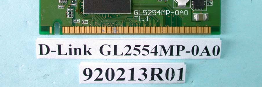
Click to zoom
Application Details
- Equipment Class
- NII - Unlicensed National Information Infrastructure TX
- Date of Grant
- Mar 12, 2003
- Application Purpose
- Original Equipment
- Date of Application
- Mar 12, 2003
- Equipment Note
- IEEE 802.11a+b/g WLAN
- Frequency Range
- 5725.00000000 - 5825.00000000
- Company
- D-Link Corporation
- Country
- United States
Documents & Files
Document Text
Text extracted from the exhibit documents filed with the FCC. Open a document above to read the original.
Users Manual
Dual-Band (draft) Wireless Network Adapter User Manual Model: GL2554MP-0A version 1.0 Manufacturer's Disclaimer Statement The information in this document is subject to change without notice and does not represent a commitment on the part of the vendor. No warranty or representation, either expressed or implied, is made with respect to the quality, accuracy or fitness for any particular purpose of this document. The manufacturer reserves the right to make changes to the content of this document and/or the products associated with it at any time without obligation to notify any person or organization of such changes. In no event will the manufacturer be liable for direct, indirect, special, incidental or consequential damages arising out of the use or inability to use this product or documentation, even if advised of the possibility of such damages. This document contains materials protected by copyright. All rights are reserved. No part of this manual may be reproduced or transmitted in any form, by any means or for any purpose without expressed written consent of its authors. Product names appearing in this document are mentioned for identification purchases only. All trademarks, product names or brand names appearing in this document are registered property of their respective owners. FCC STATEMENT This product has been tested and complies with the specifications for a Class B digital device, pursuant to Part 15 of the FCC Rules. These limits are designed to provide reasonable protection against harmful interference in a residential installation. This equipment generates, uses, and can radiate radio frequency energy and, if not installed and used according to the instructions, may cause harmful interference to radio communications. However, there is no guarantee that interference will not occur in a particular installation. If this equipment does cause harmful interference to radio or television reception, which is found by turning the equipment off and on, the user is encouraged to try to correct the interference by one or more of the following measures: z Reorient or relocate the receiving antenna z Increase the separation between the equipment or devices z Connect the equipment to an outlet other than the receiver’s z Consult a dealer or an experienced radio/TV technician for assistance FCC Caution: Any changes or modifications not expressly approved by the party responsible for compliance could void the user's authority to operate this equipment. This device complies with Part 15 of the FCC Rules. Operation is subject to the following two conditions: (1) This device may not cause harmful interference, and (2) this device must accept any interference received, including interference that may cause undesired operation. This device is intended only for OEM integrators under the following conditions: The antenna must be installed such that 20 cm is maintained between the antenna and users, and 2)The antenna should be integral if the end device is intended to be operated in 5.15 ~ 5.25GHz frequency range. As long as 2 conditions above are met, further transmitter test will not be required. However, the OEM integrator is still responsible for testing their end-product for any additional compliance requirements required with this module installed (for example, digital device emissions, PC peripheral requirements, etc.). IMPORTANT NOTE: In the event that these conditions can not be met (for example certain laptop configurations or co-location with another transmitter), then the FCC authorization is no longer considered valid and the FCC ID can not be used on the final product. In these circumstances, the OEM integrator will be responsible for re-evaluating the end product (including the transmitter) and obtaining a separate FCC authorization. End Product Labeling This transmitter module is authorized only for use in device where the antenna may be installed such that 20 cm may be maintained between the antenna and users (for example: Wireless Access Point and Wireless Router). The final end product must be labeled in a visible area with the following: “Contains TX FCC ID: KA25212AG”. Manual Information That Must be Included The OEM integrator has to be aware not to provide information to the end user regarding how to install or remove this RF module in the users manual of the end product which integrate this module. The users manual for OEM integrators end users must include the following information in a prominent location “ IMPORTANT NOTE: To comply with FCC RF exposure compliance requirements, the antenna used for this transmitter must be installed to provide a separation distance of at least 20 cm from all persons and must not be co-located or operating in conjunction with any other antenna or transmitter”. If the end product integrating this module is going to be operated in 5.15 ~ 5.25GHz frequency range, the warning statement in the user manual of the end product should include the restriction of operating this device in indoor could void the user’s authority to operate the equipment. Driver Installation Step 1: Insert the Dual-band Wireless Network Adapter into your computer. Windows Found New Hardware Wizard will come up. Select the second option and click “Next” to continue. Step 2: Select the driver to install. Click “Browse” to select the folder where you store the driver files. Click “OK” to continue. Click “Next” to continue. Step 4: Driver Found Click “Continue Anyway” to continue Step 3: Driver Installation Driver files are being saved to your Windows system. Step 4: Driver Installation Complete Click “Finish” to complete the driver setup. The following message will appear as soon as you successfully installed the driver for your Dual-band wireless network adapter. Utility Configuration Current Status Display the current settings such as Profile Name, Network Type, Wireless Mode, Current Channel, Link Status and Encryption type. Click on the “Advanced” button to change disp…
Text truncated - open the document above for the full version.
Cover Letter(s)
FCC ID: KA25212AG ADT No.920213R01 Modular Approval Request Letter Advance Data Technology March 10, 2003 Dear Application Examiner, D-Link Corporation’s IEEE 802.11a+b/g WLAN Mini PCI, FCC ID: KA25212AG, would like to have your authorization as a limited modular approval specific to the mobile device such as Access Point and Router. The requirements of Public Notice DA00- 1407 have been met and shown on the following statements. 1. “The modular transmitter must have its own RF shielding.”: The radio portion of this module has been shielded, please see exhibition External Photo. 2. “The modular transmitter must have buffered modulation/data inputs.” The EUT has buffered data inputs, it is integrated in chip AR5212. 3. “The modular transmitter must have its own power supply regulation.” The chips IF converter and RF/IF converter which will influence the frequency radiation, have to be 2.5V DC powered. The mini-pci interface provides 3.3VDC, so there are regulators in front of these chips, the part number of this regulator is TK71725SCL. 4. “The modular transmitter must comply with the antenna requirements of section 15.203 and 15.204(C).” The EUT meets the FCC antenna requirements. The spurious emission, unique antenna connector and photo of antennas are shown in the test report. 5. “The modular transmitter must be tested in a stand-alone configuration” The EUT was tested in a stand-alone configuration via a PCMCIA to mini-PCI extender. Please see section Photographs of Test Configuration in the test report, the EUT was plugged in this extender. 6. “The modular transmitter must be labeled with its own FCC ID number.” Please see exhibition Label Sample for the FCC ID of this module. And also in the exhibition Users Manual, there are instructions give to the OEM on how to label the end product. FCC ID: KA25212AG ADT No.920213R01 7. “The modular transmitter must comply with any specific rule or operating requirements applicable to the transmitter and the manufacturer must provide adequate instructions along with the module to explain any such requirements.” The EUT is compliant with all applicable FCC rules. Detail instructions for maintaining compliance are given in the Users Manual. 8. “The modular transmitter must comply with any applicable RF exposure requirements.” The EUT is compliant with all applicable RF exposure requirements. RF Exposure is addressed in the RF exposure exhibition. Please contact me if you have any further questions. Thanks for your attention. Best Regards, Dr. Alan Lane J. VP Advance Data Technology
External Photos
Page 1 ANNEX PHOTOGRAPHS OF EUT Page 2 Page 3
ID Label/Location Info
LABEL LOCATION FOR FCC ID
ID Label/Location Info
Model Name: GL2554MP-0A0 Tested To Comply With FCC Standards Made in Taiwan Rating: 3.3V FOR HOME OR OFFICE USE FCC ID: KA25212AG 57mm 22mm Prodect Name: 2.4/5GHz Wireless 54Mbps Mini PCI
Internal Photos
Page 4 Page 5 Page 6
Operational Description
FCC ID: KA25212AG ADT No.920213R01 Technical Description The transmitter of the EUT (IEEE 802.11a+b/g WLAN Mini PCI) is powered by host equipment and pluged in Mini PCI slot. The antenna is Dipole antenna. There is no antenna connector. Under normal use condition, the user has to keep at least 20cm separation distance between radiator and the body of the user. This device is a IEEE 802.11a+b/g WLAN Mini PCI which operates in both of the 5GHz and 2.4GHz bands and can not transmitting simultaneously, the maximum data rate could be 54Mbps. For more detailed instruction, please take a look at the user’s manual. FCC 15.407(c) states : The device shall automatically discontinue transmission in case of either absence of information to transmit or operational failure. These provisions are not intended to preclude the transmission of control or signaling information or the use of repetitive codes used by certain digital technologies to complete frame or burst intervals. Applicants shall include in their application for equipment authorization a description of hoe this requirement is met” Data transmission is always initiated by software, which is then pass down through the MAC, through the digital and analog baseband, and finally to the RF chip. Several special packets (ACKs, CTS, PSPoll, etc...) are initiated by the MAC. There are the only ways the digital baseband portion will turn on the RF transmitter, which it then turns off at the end of the packet. Therefore, the transmitter will be on only while one of the aforementioned packets are being transmitted.
RF Exposure Info
Report No: 920213R01 1 RF EXPOSURE REPORT REPORT NO.: RF920213R01 MODEL NO.: GL2554MP-0A0 ACCORDING: FCC Guidelines for Human Exposure IEEE C95.1 APPLICANT: D-Link Corporation ADDRESS: No. 8, Li-Hsin VII Road, Science Based Industrial Park, Hsin-Chu, Taiwan, R.O.C. ISSUED BY: Advance Data Technology Corporation LAB LOCATION: 47 14th Lin, Chiapau Tsun, Linko, Taipei, Taiwan, R.O.C. 0528 ILAC MRA Lab Code: 200102-0 Report No: 920213R01 2 RF Exposure Measurement (Mobile Device) 1. Introduction In this document, we try to prove the safety of radiation harmfulness to the human body for our product. The limit for Maximum Permissible Exposure (MPE) specified in FCC 1.1310 is followed. The Gain of the antenna used in this product is measured in a Fully Anechoic Chamber (FAC) calibrated for antenna measurement in ADT, and also the maximum total power input to the antenna is measured. Through the Friis transmission formula and the maximum gain of the antenna, we can calculate the distance, away from the product, where the limit of MPE is reached. Although the Friis transmission formula is a far field assumption, the calculated result of that is an over-prediction for near field power density. We will take that as the worst case to specify the safety range. 2. RF Exposure Limit According to FCC 1.1310: The criteria listed in the following table shall be used to evaluate the environmental impact of human exposure to radio-frequency (RF) radiation as specified in 1.1307(b) LIMITS FOR MAXIMUM PERMISSIBLE EXPOSURE (MPE) Frequency Range (MHz) Electric Field Strength (V/m) Magnetic Field Strength (A/m) Power Density (mW/cm 2 ) Average Time (minutes) (A)Limits For Occupational / Control Exposures 300-1500......F/3006 1500-100,000......56 (B)Limits For General Population / Uncontrolled Exposure 300-1500......F/15006 1500-100,000......1.030 F = Frequency in MHz Report No: 920213R01 3 3. Friis Formula Friis transmission formula : Pd = (Pout*G) / (4*pi*r 2 ) where Pd = power density in mW/cm 2 Pout = output power to antenna in mW G = gain of antenna in linear scale Pi = 3.1416 R = distance between observation point and center of the radiator in cm Pd is the limit of MPE, 1 mW/cm 2 . If we know the maximum Gain of the antenna and the total power input to the antenna, through the calculation, we will know the distance r where the MPE limit is reached. Ref. : David K. Cheng, Field and Wave Electromagnetics, Second Edition, Page 640, Eq. (11-133). 4 EUT Operating condition The software provided by Manufacturer enabled the EUT to transmit and receive data at lowest, middle and highest channel individually. 5. Classification This device is not fixed inside the host equipment, it is connected with host through wire. So it is easy to be re-located in the place where at least 20cm far away from the body of the user. Warning statement to the user for keeping at least 20cm or more separation distance with the antenna should be included in users manual. So, this device is classified as Mobile Device. Report No: 920213R01 4 6 Test Results 6.1 Antenna Gain The maximum Gain measured in Fully Anechoic Chamber are 2dBi or 1.58 (numeric) for 2.4GHz and 2dBi or 1.58 (numeric) for 5GHz. 6.2 Output Power Into Antenna & RF Exposure Distance : For Part 802.11b: CHANNEL CHANNEL FREQUENCY (MHz) OUTPUT POWER TO ANTENNA (mW) MINIMUM ALLOWABLE DISTANCE ( R ) FROM SKIN (Centi-Meter) 1241247.102.44 6243746.452.42 11246245.812.40 For Part 802.11g: CHANNEL CHANNEL FREQUENCY (MHz) OUTPUT POWER TO ANTENNA (mW) MINIMUM ALLOWABLE DISTANCE ( R ) FROM SKIN (Centi-Meter) 1241247.972.45 6243747.212.44 11246246.882.43 For Part 802.11a: CHANNEL CHANNEL FREQUENCY (MHz) OUTPUT POWER TO ANTENNA (mW) MINIMUM ALLOWABLE DISTANCE ( R ) FROM SKIN (Centi-Meter) 1518035.972.13 4524035.162.11 5526047.972.45 8532049.092.49 9574733.652.06 12580525.351.79 The minimum allowable distance is very close to the enclosure of the antenna. So, the user has no need to worry about the harmfulness of radiation. But it is recommended to always keep, at least, 20cm separation distance with the antenna.
Test Report
FCC ID: KA25212AG Report No.: RF920213R011Issued: Mar. 9, 2003 FCC TEST REPORT REPORT NO.: RF920213R01 MODEL NO.: GL2554MP-0A0 RECEIVED: Feb. 13, 2003 TESTED: Feb. 18 ~ Mar. 4, 2003 APPLICANT: D-Link Corporation ADDRESS: No. 8, Li-Hsin VII Road, Science Based Industrial Park, Hsin-Chu, Taiwan, R.O.C. ISSUED BY: Advance Data Technology Corporation LAB LOCATION: 47 14 th Lin, Chiapau Tsun, Linko, Taipei, Taiwan, R.O.C. This test report consists of 139 pages in total. It may be duplicated completely for legal use with the approval of the applicant. It should not be reproduced except in full, without the written approval of our laboratory. The client should not use it to claim product endorsement by CNLA, NVLAP or any government agencies. The test results in the report only apply to the tested sample. 0528 ILAC MRA Lab Code: 200102-0 FCC ID: KA25212AG Report No.: RF920213R012Issued: Mar. 9, 2003 Table of Contents 1.CERTIFICATION ........................................................................................................................ 6 2.SUMMARY OF TEST RESULTS................................................................................................ 7 3.GENERAL INFORMATION ........................................................................................................ 9 3.1GENERAL DESCRIPTION OF EUT........................................................................................... 9 3.2DESCRIPTION OF TEST MODES........................................................................................... 10 3.3GENERAL DESCRIPTION OF APPLIED STANDARDS...........................................................11 3.4DESCRIPTION OF SUPPORT UNITS..................................................................................... 12 4.TEST TYPES AND RESULTS (For Part 802.11b & draft 802.11g) .......................................... 13 4.1CONDUCTED EMISSION MEASUREMENT........................................................................... 13 4.1.1LIMITS OF CONDUCTED EMISSION MEASUREMENT ........................................................ 13 4.1.2TEST INSTRUMENTS ............................................................................................................. 13 4.1.3TEST PROCEDURES .............................................................................................................. 14 4.1.4DEVIATION FROM TEST STANDARD .................................................................................... 14 4.1.5TEST SETUP ........................................................................................................................... 15 4.1.6EUT OPERATING CONDITIONS............................................................................................. 15 4.1.7TEST RESULTS ....................................................................................................................... 16 4.2RADIATED EMISSION MEASUREMENT................................................................................ 22 4.2.1LIMITS OF RADIATED EMISSION MEASUREMENT ............................................................. 22 4.2.2TEST INSTRUMENTS ............................................................................................................. 23 4.2.3TEST PROCEDURES .............................................................................................................. 24 4.2.4DEVIATION FROM TEST STANDARD .................................................................................... 24 4.2.5TEST SETUP ........................................................................................................................... 25 4.2.6EUT OPERATING CONDITIONS............................................................................................. 25 4.2.7TEST RESULTS (A) ................................................................................................................. 26 4.2.8TEST RESULTS (B) ................................................................................................................. 33 4.36dB BANDWIDTH MEASUREMENT ....................................................................................... 40 4.3.1LIMITS OF 6dB BANDWIDTH MEASUREMENT.................................................................... 40 4.3.2TEST INSTRUMENTS ............................................................................................................. 40 4.3.3TEST PROCEDURE ................................................................................................................ 41 4.3.4DEVIATION FROM TEST STANDARD .................................................................................... 41 4.3.5TEST SETUP ........................................................................................................................... 41 FCC ID: KA25212AG Report No.: RF920213R013Issued: Mar. 9, 2003 4.3.6EUT OPERATING CONDITIONS............................................................................................. 41 4.3.7TEST RESULTS ....................................................................................................................... 42 4.3.8TEST RESULTS ....................................................................................................................... 46 4.4MAXIMUM PEAK OUTPUT POWER ....................................................................................... 50 4.4.1LIMITS OF MAXIMUM PEAK OUTPUT POWER MEASUREMENT ....................................... 50 4.4.2INSTRUMENTS........................................................................................................................ 50 4.4.3TEST PROCEDURES .............................................................................................................. 51 4.4.4DEVIATION FROM TEST STANDARD .................................................................................... 51 4.4.5TEST SETUP .......................................................…
Text truncated - open the document above for the full version.
Test Report
FCC ID: KA25212AG Report No.: RF920213R01108Issued: Mar. 9, 2003 5.4 PEAK POWER EXCURSION MEASUREMENT 5.4.1 LIMITS OF PEAK POWER EXCURSION MEASUREMENT Frequency BandLimit 5.15 – 5.25 GHz13dB 5.25 – 5.35 GHz13dB 5.725 – 5.825 GHz13dB 5.4.2 TEST INSTRUMENTS Description & ManufacturerModel No.Serial No.Calibrated Until PEAK POWER SENSORE9327AUS40440722July 30, 2003 POWER METERE4416AGB41291118July 30, 2003 NOTE: The calibration interval of the above test instruments is 12 months and the calibrations are traceable to NML/ROC and NIST/USA. FCC ID: KA25212AG Report No.: RF920213R01109Issued: Mar. 9, 2003 5.4.3 TEST PROCEDURE 1. The transmitter output was connected to the spectrum analyzer. 2. Set the spectrum bandwidth span to view the entire spectrum. 3. Using peak detector and Max-hold function for Trace 1 (RB=1MHz, VB=3MHz) and 2 (RB=1MHz, VB=300kHz). 4. The largest difference between Trace 1 and Trace 2 in any 1MHz band on any frequency was recorded. 5.4.4 DEVIATION FROM TEST STANDARD No deviation 5.4.5 TEST SETUP 5.4.6 EUT OPERATING CONDITIONS The software provided by client to enable the EUT under transmission condition continuously at specific channel frequencies individually. EUT Power Meter FCC ID: KA25212AG Report No.: RF920213R01110Issued: Mar. 9, 2003 5.4.7 TEST RESULTS EUT IEEE 802.11a+b/g WLAN Mini PCI MODEL GL2554MP-0A0 ENVIRONMENTAL CONDITIONS 24deg. C, 65%RH, 1005hPa INPUT POWER (SYSTEM) 120Vac, 60 Hz TESTED BY Ansen Lei CHANNEL CHANNEL FREQUENCY (MHz) PEAK POWER EXCURSION (dB) PEAK to AVERAGE EXCURSION LIMIT (dB) PASS/FAIL 151805.8313PASS 452404.9113PASS 552608.2313PASS 853204.8913PASS 957455.7813PASS 1258055.2613PASS FCC ID: KA25212AG Report No.: RF920213R01111Issued: Mar. 9, 2003 CHANNEL 1 FCC ID: KA25212AG Report No.: RF920213R01112Issued: Mar. 9, 2003 CHANNEL 4 FCC ID: KA25212AG Report No.: RF920213R01113Issued: Mar. 9, 2003 CHANNEL 5 FCC ID: KA25212AG Report No.: RF920213R01114Issued: Mar. 9, 2003 CHANNEL 8 FCC ID: KA25212AG Report No.: RF920213R01115Issued: Mar. 9, 2003 CHANNEL 9 FCC ID: KA25212AG Report No.: RF920213R01116Issued: Mar. 9, 2003 CHANNEL 12 FCC ID: KA25212AG Report No.: RF920213R01117Issued: Mar. 9, 2003 5.5 PEAK POWER SPECTRAL DENSITY MEASUREMENT 5.5.1 LIMITS OF PEAK POWER SPECTRAL DENSITY MEASUREMENT Frequency BandLimit 5.15 – 5.25GHz4dBm 5.25 – 5.35GHz11dBm 5.725 – 5.825GHz17dBm 5.5.2 TEST INSTRUMENTS Description & ManufacturerModel No.Serial No.Calibrated Until SPECTRUM ANALYZERFSEK30100049July 24, 2003 NOTE The calibration interval of the above test instruments is 12 months and the calibrations are traceable to NML/ROC and NIST/USA. FCC ID: KA25212AG Report No.: RF920213R01118Issued: Mar. 9, 2003 5.5.3 TEST PROCEDURES 1. The transmitter output was connected to the spectrum analyzer. 2. Set RBW=1MHz, VBW=3MHz. The PPSD is the highest level found across the emission in any 1MHz band. 5.5.4 DEVIATION FROM TEST STANDARD No deviation 5.5.5 TEST SETUP 5.5.6 EUT OPERATING CONDITIONS Same as 5.3.6 EUT SPECTRUM ANALYZER FCC ID: KA25212AG Report No.: RF920213R01119Issued: Mar. 9, 2003 5.5.7 TEST RESULTS EUT IEEE 802.11a+b/g WLAN Mini PCI MODEL GL2554MP-0A0 ENVIRONMENTAL CONDITIONS 24deg. C, 65%RH, 1005hPa INPUT POWER (SYSTEM) 120Vac, 60 Hz TESTED BY Ansen Lei CHANNEL CHANNEL FREQUENCY (MHz ) RF POWER LEVEL IN 1MHz BW (dBm) MAXIMUM LIMIT (dBm) PASS/FAIL 15180-1.864PASS 45240-1.734PASS 55260-0.3611PASS 853200.2111PASS 95745-1.7917PASS 125805-2.8917PASS FCC ID: KA25212AG Report No.: RF920213R01120Issued: Mar. 9, 2003 CHANNEL 1 FCC ID: KA25212AG Report No.: RF920213R01121Issued: Mar. 9, 2003 CHANNEL 4 FCC ID: KA25212AG Report No.: RF920213R01122Issued: Mar. 9, 2003 CHANNEL 5 FCC ID: KA25212AG Report No.: RF920213R01123Issued: Mar. 9, 2003 CHANNEL 8 FCC ID: KA25212AG Report No.: RF920213R01124Issued: Mar. 9, 2003 CHANNEL 9 FCC ID: KA25212AG Report No.: RF920213R01125Issued: Mar. 9, 2003 CHANNEL 12 FCC ID: KA25212AG Report No.: RF920213R01126Issued: Mar. 9, 2003 5.6 FREQUENCY STABILITY 5.6.1 LIMITS OF FREQUENCY STABILITY MEASUREMENT The frequency tolerance of the carrier signal shall be maintained within +/- 0.02% of the operating frequency over a temperature variation of –30 degrees to 50 degrees C at normal supply voltage, and for a variation in the primary supply voltage from 85% to 115% of the rated supply voltage at a temperature of 20 degrees C. 5.6.2 TEST INSTRUMENTS Description & ManufacturerModel No.Serial No.Calibrated Until ANRITSU SPECTRUM ANALYZERMS2667CM10281Mar. 15, 2003 WIT STANDARD TEMPERATURE AND HUMIDITY CHAMBER TH-4S-CW901030Jun. 24, 2003 NOTE: The calibration interval of the above test instruments is 12 months and the calibrations are traceable to NML/ROC and NIST/USA. 5.6.3 TEST PROCEDURE 1. The EUT was placed inside the environmental test chamber and powered by nominal DC voltage. 2. Turn the EUT on and couple its output to a spectrum analyzer. 3. Turn the EUT off and set the chamber to the highest temperature specified. 4. Allow sufficient time (approximately 30 min) for the temperature of the chamber to stabilize, turn the EUT on and measure the operating frequency after 2, 5, and 10 minutes. 5. Repeat step 2 and 3 with the temperature chamber set to the lowest temperature. 6. The test chamber was allowed to stabilize at +20 degree C for a minimum of 30 minutes. The supply voltage was then adjusted on the EUT from 85% to 115% and the frequency record. FCC ID: KA25212AG Report No.: RF920213R01127Issued: Mar. 9, 2003 5.6.4 DEVIATION FROM TEST STANDARD No deviation 5.6.5 TEST SETUP 5.6.6 EUT OPERATING CONDITION Same as Item 4.1.6 Spectrum Analyzer DC Power Supply Te mpera ture FCC ID: KA25212AG Report No.: RF920213R01128Issued: Mar. 9, 2003 5.6.7 TEST RESULTS Operating frequency: 5180MHzLimit : ± 0.02% 2 minute5 minute10 minute Temp. (°C) Power supply (VDC) (MHz)(%)(MHz)(%)(MHz)(%) 126.5 5319.9202-0.00150005319.9206-0.00149255319.9205-0.0014944 110.0 5319.9202-0.00150005319.9208-0.00148875319.9205-0.0014944 50 93.5 5319.9204-0.00149625319.9207-0.…
Text truncated - open the document above for the full version.
Test Setup Photos
FCC ID: KA25212AG Report No.: RF920213R01135Issued: Mar. 9, 2003 6. PHOTOGRAPHS OF THE TEST CONFIGURATION CONDUCTED EMISSION TEST FCC ID: KA25212AG Report No.: RF920213R01136Issued: Mar. 9, 2003 FCC ID: KA25212AG Report No.: RF920213R01137Issued: Mar. 9, 2003 RADIATED EMISSION TEST FCC ID: KA25212AG Report No.: RF920213R01138Issued: Mar. 9, 2003
Contact Information
Applicant
Brett Adair(General Counsel)
Technical Contact
Advance Data TEchnology CorporationEllis Wu
[email protected]+886 3 327 0910
13-1, Lane 19, WenShan 3rd St · Taoyuan · Taiwan
Test Firm
Bureau Veritas CPS (H.K.) Ltd. Taoyuan BranchRichard Chen
Technical Specifications
| # | Rule Parts | Frequency Range | Power Output |
|---|---|---|---|
| 3 | 15E | 5.72 GHz - 5.83 GHz | 34.00 mW |
Other Applications from D-Link Corporation

KA2CS6012A1
Jul 07, 20262K Fixed Indoor Cloud Camera, 2K Fixed Indoor Wi-Fi Camera
Equipment Class
DTS - Digital Transmission SystemKA2AE65UA1
Mar 02, 2026Wi-Fi 7 BE6500 USB 3.0 Dongle
Equipment Class
NII - Unlicensed National Information Infrastructure TXKA2APE9560A1
Nov 17, 2025BE9500 Celling mount Access Point
Equipment Class
6ID - 15E 6 GHz Low Power Indoor Access PointKA2AX9UA1
Dec 04, 2024AX900 Wi-Fi 6 USB Adapter, Wi-Fi 6 AX900 USB 2.0 Dongle
Equipment Class
DSS - Part 15 Spread Spectrum TransmitterKA2AC13UA1
Dec 04, 2024AC1300 Wi-Fi 5 USB Adapter, Wi-Fi 5 AC1300 USB 2.0 Dongle
Equipment Class
DTS - Digital Transmission System