KA2AP3662A1Wireless AC1200 Dual Band Outdoor PoE Access Point
D-Link Corporation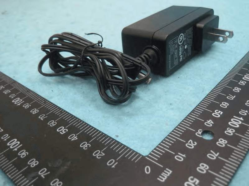
Click to zoom
Application Details
- Equipment Class
- NII - Unlicensed National Information Infrastructure TX
- Date of Grant
- Jan 27, 2015
- Application Purpose
- Original Equipment
- Date of Application
- Jan 26, 2015
- Equipment Note
- Wireless AC1200 Dual Band Outdoor PoE Access Point
- Frequency Range
- 5180.00000000 - 5240.00000000
- Company
- D-Link Corporation
- Country
- United States
Documents & Files
Document Text
Text extracted from the exhibit documents filed with the FCC. Open a document above to read the original.
Users Manual
This document will guide you through the basic installation process for your new D-Link Dual Band Outdoor Access Point Building Networks for People DAP-3662 Documentation also available via the D-Link Website Quick Installation Guide Wireless AC1200 Concurrent Dual Band Outdoor PoE Access Point Quick Installation Guide Краткое руководство по установке Guía de Instalación Rápida Guia de Instalação Rápida 快速安裝指南 Petunjuk Pemasangan Cepat クイックインストールガイド 2 D-Link DAP-3662 Quick Install Guide 2 ENGLISH Important Information This product should ONLY be installed by an experienced installer who is familiar with local building and safety codes and, where applicable, is licensed by the appropriate authorities. Failure to employ an experienced installer may render the D-Link product warranty void and may also expose the end user or the service provider to legal and financial liabilities. D-Link and its resellers or distributors expressly disclaim any and all liabilities for injury, damage, or violation of regulations due to the improper installation of outdoor units or antennas. A safety grounding system is necessary to protect your outdoor installation from lightning strikes and the build-up of static electricity. Direct grounding of an outdoor AP is very important and can protect your networks from brutal outdoor environments and devastating ESD attacks. The grounding system must comply with the National Electrical Code and safety standards that apply in your country and/or region. Always check with a qualified electrician if you are in doubt as to whether your outdoor installation is properly grounded. Quick Install Guide This installation guide provides basic instructions for installing the DAP-3662 Wireless AC1200 Concurrent Dual Band Outdoor PoE Access Point on your network. For additional information about how to use the Access Point, please see the datasheet and user manual from the D-Link support website. Minimum System Requirements Computer with Windows, MAC OS, or Linux- based operating system, and an Ethernet adapter installed -Internet Explorer 7.0, Mozilla Firefox® version 12.0, Safari 4.0, or Chrome 20.0 or newer Package Contents -DAP-3662 Wireless AC1200 Concurrent Dual Band Outdoor PoE Access Point -Installation CD-ROM -Quick Installation Guide -PoE Injector -Po wer Adapter (48 V/ 0.5 A) 1 -Mounting kit (Wall/Pole Mount) -Stainless steel mount base x 1 -Stainless tie back straps x 2 -Wall screw x 4 -Wall plug x4 -Stainless mount screw (hexagonal hole) x1 -Hexagon Socket Spanner -Two LAN Port Waterproof Enclosure -Grounding W ire If any of the above items are missing, please contact your reseller. 1 Using a power supply with a different voltage rating or PoE injector than the one included with the DAP-3662 will cause damage and void the warranty for this product. 3 D-Link DAP-3662 Quick Install Guide 3 ENGLISH Physical Installation STEP 1: Connect an Ethernet Cable to the LAN1 (PoE) Port on the AP. STEP 2: Mount the AP to a Pole or Wall 2A: Mounting The DAP-3662 On A Pole Secure mount base to the pole with two stainless tie back strap sets. Ensure that the tie back is locked securely. Align the DAP-3662 with the mounting plate Once aligned, slide the device down so that the mounting plate securely locks into the DAP-3662 2B: Mounting The DAP-3662 On A Wall Securely mount the base to the wall using wall plug and wall screw. Align the DAP-3662 with the mounting plate 4 D-Link DAP-3662 Quick Install Guide 4 ENGLISH Once aligned, slide the device down so that the mounting plate securely locks into the DAP-3662 STEP 3: Install Mount Screw to Fix DAP-3662 On A Mounting (Pole/ Wall Mount base) Use the included mount screw (hexagonal hole) to lock the DAP-3662 to the pole/wall mount With the included hexagon socket spanner, tighten the mount screw until the DAP-3662 is secured. STEP 4: Connect Grounding Wire A grounding wire is recommended to protect your device from lightning strikes and the buildup of static electricity. Attach the grounding wire to the DAP-3662 using the included screw. Tighten the grounding wire to the DAP-3662 until it is securely attached. Attach the other end of the grounding wire to either the wall or pole mount. Ensure that the wall or pole mount is connected to an electrical ground. 5 D-Link DAP-3662 Quick Install Guide 5 ENGLISH STEP 5: Connect the AP to Your Network A. Connect the Ethernet cable (connected to the AP in STEP 1) from the AP to the “P+DATA OUT” port on the PoE Injector. B. Connect an Ethernet cable from a router/ switch or PC to the “DATA IN” port on the PoE Injector. C. Attach the power adapter to the connector labeled “POWER IN” on the PoE Injector, and attach it into an electrical outlet. Configuration If you are configuring the AP locally, connect a PC to the PoE Injector “DATA IN” port using an Ethernet cable. A. Assign a static IP address to your PC which is in the same network segment with the device. As the default IP address of this unit is 192.168.0.50, you may choose any address from 192.168.0.1 to 192.168.0.254, except 192.168.0.50. B. Open a web browser and go to http://192.168.0.50. Enter admin as your username and leave the password blank to log into the web UI. Now you can configure the AP via web UI. A C B P+DATA OUT DATA IN PoE Injector POWER IN Router or SwitchComputer AP LAN1 (PoE) FCC Statement: Federal Communication Commission Interference Statement This equipment has been tested and found to comply with the limits for a Class B digital device, pursuant to Part 15 of the FCC Rules. These limits are designed to provide reasonable protection against harmful interference in a residential installation. This equipment generates, uses and can radiate radio frequency energy and, if not installed and used in accordance with the instructions, may cause harmful interference to radio communications. However, there is no guarantee that interference will not occur in a particular installation. If this equipment does cause harmful interfere…
Text truncated - open the document above for the full version.
External Photos
Report No.: 4N2206 SPORTON International Inc. PAGE NUMBER : 1 OF 6 TEL : 886-3-327-3456 ISSUED DATE : Jan. 14, 2015 FAX : 886-3-327-0973 Photographs of EUT Report No.: 4N2206 SPORTON International Inc. PAGE NUMBER : 2 OF 6 TEL : 886-3-327-3456 ISSUED DATE : Jan. 14, 2015 FAX : 886-3-327-0973 Report No.: 4N2206 SPORTON International Inc. PAGE NUMBER : 3 OF 6 TEL : 886-3-327-3456 ISSUED DATE : Jan. 14, 2015 FAX : 886-3-327-0973 Adapter Brand Name: LEI Model No.: MU24-B480050-A1 Report No.: 4N2206 SPORTON International Inc. PAGE NUMBER : 4 OF 6 TEL : 886-3-327-3456 ISSUED DATE : Jan. 14, 2015 FAX : 886-3-327-0973 PoE Brand Name: LanReady Model No.: PE03G Report No.: 4N2206 SPORTON International Inc. PAGE NUMBER : 5 OF 6 TEL : 886-3-327-3456 ISSUED DATE : Jan. 14, 2015 FAX : 886-3-327-0973 Report No.: 4N2206 SPORTON International Inc. PAGE NUMBER : 6 OF 6 TEL : 886-3-327-3456 ISSUED DATE : Jan. 14, 2015 FAX : 886-3-327-0973 Ground Cable
ID Label/Location Info
Label: Label here
Internal Photos
Report No.: 4N2206 SPORTON International Inc. PAGE NUMBER : 1 OF 12 TEL : 886-3-327-3456 ISSUED DATE : Jan. 14, 2015 FAX : 886-3-327-0973 Photographs of EUT Report No.: 4N2206 SPORTON International Inc. PAGE NUMBER : 2 OF 12 TEL : 886-3-327-3456 ISSUED DATE : Jan. 14, 2015 FAX : 886-3-327-0973 Report No.: 4N2206 SPORTON International Inc. PAGE NUMBER : 3 OF 12 TEL : 886-3-327-3456 ISSUED DATE : Jan. 14, 2015 FAX : 886-3-327-0973 Report No.: 4N2206 SPORTON International Inc. PAGE NUMBER : 4 OF 12 TEL : 886-3-327-3456 ISSUED DATE : Jan. 14, 2015 FAX : 886-3-327-0973 Report No.: 4N2206 SPORTON International Inc. PAGE NUMBER : 5 OF 12 TEL : 886-3-327-3456 ISSUED DATE : Jan. 14, 2015 FAX : 886-3-327-0973 Report No.: 4N2206 SPORTON International Inc. PAGE NUMBER : 6 OF 12 TEL : 886-3-327-3456 ISSUED DATE : Jan. 14, 2015 FAX : 886-3-327-0973 Report No.: 4N2206 SPORTON International Inc. PAGE NUMBER : 7 OF 12 TEL : 886-3-327-3456 ISSUED DATE : Jan. 14, 2015 FAX : 886-3-327-0973 Report No.: 4N2206 SPORTON International Inc. PAGE NUMBER : 8 OF 12 TEL : 886-3-327-3456 ISSUED DATE : Jan. 14, 2015 FAX : 886-3-327-0973 Report No.: 4N2206 SPORTON International Inc. PAGE NUMBER : 9 OF 12 TEL : 886-3-327-3456 ISSUED DATE : Jan. 14, 2015 FAX : 886-3-327-0973 Report No.: 4N2206 SPORTON International Inc. PAGE NUMBER : 10 OF 12 TEL : 886-3-327-3456 ISSUED DATE : Jan. 14, 2015 FAX : 886-3-327-0973 Report No.: 4N2206 SPORTON International Inc. PAGE NUMBER : 11 OF 12 TEL : 886-3-327-3456 ISSUED DATE : Jan. 14, 2015 FAX : 886-3-327-0973 Report No.: 4N2206 SPORTON International Inc. PAGE NUMBER : 12 OF 12 TEL : 886-3-327-3456 ISSUED DATE : Jan. 14, 2015 FAX : 886-3-327-0973
RF Exposure Info
Report No.: FR4N2206 FCC ID: KA2AP3662A1 Page No. : B1 of B3 Appendix B. Maximum Permissible Exposure Report No.: FR4N2206 FCC ID: KA2AP3662A1 Page No. : B2 of B3 1. Maximum Permissible Exposure 1.1. Applicable Standard Systems operating under the provisions of this section shall be operated in a manner that ensures that the public is not exposed to radio frequency energy levels in excess limit for maximum permissible exposure. In accordance with 47 CFR FCC Part 2 Subpart J, section 2.1091 this device has been defined as a mobile device whereby a distance of 0.2 m normally can be maintained between the user and the device. (A) Limits for Occupational / Controlled Exposure Frequency Range (MHz) Electric Field Strength (E) (V/m) Magnetic Field Strength (H) (A/m) Power Density (S) (mW/ cm²) Averaging Time |E|²,|H|² or S (minutes) 0.3-3.0 614 1.63 (100)* 6 3.0-30 1842 / f 4.89 / f (900 / f)* 6 30-300 61.4 0.163 1.0 6 300-1500 F/300 6 1500-100,000 5 6 (B) Limits for General Population / Uncontrolled Exposure Frequency Range (MHz) Electric Field Strength (E) (V/m) Magnetic Field Strength (H) (A/m) Power Density (S) (mW/ cm²) Averaging Time |E|²,|H|² or S (minutes) 0.3-1.34 614 1.63 (100)* 30 1.34-30 824/f 2.19/f (180/f)* 30 30-300 27.5 0.073 0.2 30 300-1500 F/1500 30 1500-100,000 1.0 30 Note: f = frequency in MHz ; *Plane-wave equivalent power density 1.2. MPE Calculation Method E (V/m) = d GP30 Power Density: Pd (W/m²) = 377 2 E E = Electric field (V/m) P = Average RF output power (W) G = EUT Antenna numeric gain (numeric) d = Separation distance between radiator and human body (m) The formula can be changed to Pd = 2 377 30 d GP From the EUT RF output power, the minimum mobile separation distance, d=0.23m, as well as the gain of the used antenna, the RF power density can be obtained. Report No.: FR4N2206 FCC ID: KA2AP3662A1 Page No. : B3 of B3 1.3. Calculated Result and Limit Exposure Environment: General Population / Uncontrolled Exposure For 5GHz UNII Band: Antenna Type : Embedded Antenna Conducted Power for IEEE 802.11ac MCS0/Nss1 VHT20 : 24.55dBm The maximum combined Average Output Power Distance (m) Antenna Gain (dBi) Antenna Gain (numeric) (dBm) (mW) Power Density (S) (mW/cm²) Limit of Power Density (S) (mW/cm²) Test Result 0.23 6.20 4.1687 24.5492 285.0519 0.178846 1 Complies For 5GHz ISM Band: Antenna Type : Embedded Antenna Conducted Power for IEEE 802.11a: 28.74dBm The maximum combined Average Output Power Distance (m) Antenna Gain (dBi) Antenna Gain (numeric) (dBm) (mW) Power Density (S) (mW/cm²) Limit of Power Density (S) (mW/cm²) Test Result 0.23 6.20 4.1687 28.7375 747.7375 0.469141 1 Complies For 2.4GHz Band: Antenna Type : Embedded Antenna Conducted Power for IEEE 802.11g: 27.96 dBm The maximum combined Average Output Power Distance (m) Antenna Gain (dBi) Antenna Gain (numeric) (dBm) (mW) Power Density (S) (mW/cm²) Limit of Power Density (S) (mW/cm²) Test Result 0.23 6.10 4.0738 27.9568 624.7154 0.383034 1 Complies Conclusion: Both of the WLAN 2.4GHz Band and WLAN 5GHz Band can transmit simultaneously, the formula of calculated the MPE is: CPD1 / LPD1 + CPD2 / LPD2 + ......etc. < 1 CPD = Calculation power density LPD = Limit of power density Therefore, the worst-case situation is 0.383034 / 1 + 0.469141 / 1 = 0.852175, which is less than “1”. This confirmed that the device comply with FCC 1.1310 MPE limit.
Test Report
Report No.: FR4N2206 FCC ID: KA2AP3662A1 Page No. : C1 of C3 Appendix C. Radiated Emission Co-location Report Report No.: FR4N2206 FCC ID: KA2AP3662A1 Page No. : C2 of C3 1. Results of Radiated Emissions for Co-located Temperature 26°C Humidity 68% Test Engineer Peter Wu Configurations 2.4GHz + 5GHz Horizontal Report No.: FR4N2206 FCC ID: KA2AP3662A1 Page No. : C3 of C3 Vertial
Test Report
Report No.: FR4N2206 FCC ID: KA2AP3662A1 Page No. : D1 of D2 Appendix D. Maximum e.i.r.p. at any elevation angle above 30 degrees Report No.: FR4N2206 FCC ID: KA2AP3662A1 Page No. : D2 of D2 1. Maximum e.i.r.p. at any elevation angle above 30 degrees Mode Bandwidth (MHz) Frequency (MHz) Setting Maximum Conducted Output Power (dBm) Elevation angle above 30∘ Max gain (dBi) Elevation angle above 30∘ Max EIRP (dBm) EIRP Limit (dBm) Complies 5180 20 24.14 -3.700 20.44 21 Pass 5200 20 24.40 -3.700 20.70 21 Pass Configuration IEEE 802.11a 20 5240 20 24.14 -3.700 20.44 21 Pass 5180 20 24.02 -3.700 20.32 21 Pass 5200 20 24.34 -3.700 20.64 21 Pass Configuration IEEE 802.11ac 20 5240 20.5 24.55 -3.700 20.85 21 Pass 5190 19.5 22.72 -3.700 19.02 21 Pass Configuration IEEE 802.11ac 40 5230 21.5 24.24 -3.700 20.54 21 Pass Configuration IEEE 802.11ac 80 5210 18.5 21.20 -3.700 17.50 21 Pass
Test Report
SPORTON International Inc. No. 52, Hwa Ya 1st Rd., Hwa Ya Technology Park, Kwei-Shan Hsiang, Tao Yuan Hsien, Taiwan, R.O.C. Ph: 886-3-327-3456 / FAX: 886-3-327-0973 / www.sporton.com.tw Report Format Version: Rev. 01 FCC RADIO TEST REPORT Applicant’s company D-Link Corporation Applicant Address No.289, Sinhu 3rd Rd., Neihu District, Taipei City 114, Taiwan, R.O.C. FCC ID KA2AP3662A1 Product Name Wireless AC1200 Dual Band Outdoor PoE Access Point Brand Name D-Link Model No. DAP-3662 Test Rule Part(s) 47 CFR FCC Part 15 Subpart E § 15.407 Test Freq. Range 5150 ~ 5250MHz Received Date Oct. 22, 2014 Final Test Date Dec. 08, 2014 Submission Type Original Equipment Statement Test result included is for the IEEE 802.11n and IEEE 802.11a/ac of the product. The test result in this report refers exclusively to the presented test model / sample. Without written approval of SPORTON International Inc., the test report shall not be reproduced except in full. The measurements and test results shown in this test report were made in accordance with the procedures and found in compliance with the limit given in ANSI C63.10-2013, 47 CFR FCC Part 15 Subpart E, KDB789033 D02 v01, KDB662911 D01 v02r01, KDB644545 D03 v01. The test equipment used to perform the test is calibrated and traceable to NML/ROC. Report No.: FR4N2206AB Report Format Version: Rev. 01 Page No. : i of ii FCC ID: KA2AP3662A1 Issued Date : Jan. 26, 2015 Table of Contents 1. CERTIFICATE OF COMPLIANCE ......................................................................................................................... 1 2. SUMMARY OF THE TEST RESULT .......................................................................................................................... 2 3. GENERAL INFORMATION .................................................................................................................................. 3 3.1. Product Details....................................................................................................................................................................................3 3.2. Accessories .........................................................................................................................................................................................5 3.3. Table for Filed Antenna.......................................................................................................................................................................6 3.4. Table for Carrier Frequencies .............................................................................................................................................................7 3.5. Table for Test Modes ...........................................................................................................................................................................8 3.6. Table for Testing Locations..................................................................................................................................................................9 3.7. Table for Supporting Units ...................................................................................................................................................................9 3.8. Table for Parameters of Test Software Setting ...................................................................................................................................10 3.9. EUT Operation during Test .................................................................................................................................................................10 3.10. Duty Cycle ........................................................................................................................................................................................11 3.11. Test Configurations ...........................................................................................................................................................................12 4. TEST RESULT ................................................................................................................................................... 15 4.1. AC Power Line Conducted Emissions Measurement.........................................................................................................................15 4.2. 26dB Bandwidth and 99% Occupied Bandwidth Measurement......................................................................................................21 4.3. Maximum Conducted Output Power Measurement .........................................................................................................................33 4.4. Power Spectral Density Measurement ..............................................................................................................................................37 4.5. Radiated Emissions Measurement ....................................................................................................................................................43 4.6. Band Edge Emissions Measurement .................................................................................................................................................59 4.7. Frequency Stability Measurement ....................................................................................................................................................64 4.8. Antenna Requirements .....................................................................................................................................................................66 5. LIST OF MEASURING EQUIPMENTS ................................................................................................................... 67 6. MEASUREMENT UNCERTAINTY.......................................................................................................................... 69 APPE…
Text truncated - open the document above for the full version.
Test Setup Photos
Report No.: FR4N2206 FCC ID: KA2AP3662A1 Page No. : A1 of A5 Appendix A. Test Photos Report No.: FR4N2206 FCC ID: KA2AP3662A1 Page No. : A2 of A5 1. Photographs of Conducted Emissions Test Configuration FRONT VIEW REAR VIEW Report No.: FR4N2206 FCC ID: KA2AP3662A1 Page No. : A3 of A5 2. Photographs of Radiated Emissions Test Configuration Test Configuration: 9kHz ~30MHz FRONT VIEW REAR VIEW Report No.: FR4N2206 FCC ID: KA2AP3662A1 Page No. : A4 of A5 Test Configuration: 30MHz~1GHz FRONT VIEW REAR VIEW Report No.: FR4N2206 FCC ID: KA2AP3662A1 Page No. : A5 of A5 Test Configuration: Above 1GHz FRONT VIEW REAR VIEW
Contact Information
Applicant
Brett Adair(General Counsel)
Technical Contact
Sporton International Inc.Christy Fan
[email protected]886-3-656-9065
No.8, Lane 724, Bo-ai St. · Taiwan
Non-Technical Contact
Sporton International Inc.Christy Fan
[email protected]886-3-656-9065
Test Firm
Sporton International Inc.Alex Chen
Technical Specifications
| # | Rule Parts | Frequency Range | Power Output |
|---|---|---|---|
| 1 | 15E | 5.18 GHz - 5.24 GHz | 285.00 mW |
Other Applications from D-Link Corporation

KA2CS6012A1
Jul 07, 20262K Fixed Indoor Cloud Camera, 2K Fixed Indoor Wi-Fi Camera
Equipment Class
DTS - Digital Transmission SystemKA2AE65UA1
Mar 02, 2026Wi-Fi 7 BE6500 USB 3.0 Dongle
Equipment Class
NII - Unlicensed National Information Infrastructure TXKA2APE9560A1
Nov 17, 2025BE9500 Celling mount Access Point
Equipment Class
6ID - 15E 6 GHz Low Power Indoor Access PointKA2AX9UA1
Dec 04, 2024AX900 Wi-Fi 6 USB Adapter, Wi-Fi 6 AX900 USB 2.0 Dongle
Equipment Class
DSS - Part 15 Spread Spectrum TransmitterKA2AC13UA1
Dec 04, 2024AC1300 Wi-Fi 5 USB Adapter, Wi-Fi 5 AC1300 USB 2.0 Dongle
Equipment Class
DTS - Digital Transmission System