KA2AP3712A120km Long Range 802.11ac Wireless Bridge
D-Link Corporation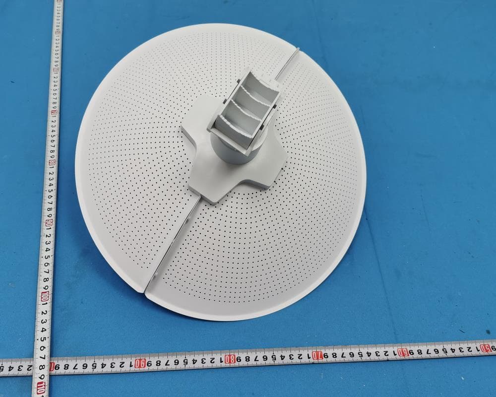
Click to zoom
Application Details
- Equipment Class
- NII - Unlicensed National Information Infrastructure TX
- Date of Grant
- Aug 09, 2020
- Application Purpose
- Original Equipment
- Date of Application
- Jul 26, 2020
- Equipment Note
- 20km Long Range 802.11ac Wireless Bridge
- Frequency Range
- 5745.00000000 - 5825.00000000
- Company
- D-Link Corporation
- Country
- United States
Documents & Files
Document Text
Text extracted from the exhibit documents filed with the FCC. Open a document above to read the original.
Users Manual
Additional documentation is also available on the D-Link website DAP-3712 Quick Installation Guide 20 km Long Range 802.11ac Wireless Bridge Contents English 1 Quick Installation Guide 1 ENGLISH Hardware Overview LED Indicators Figure 1: DAP-3712 LEDs #LEDDescription 1 Signal Strength Signal strength indicators. One light indicates a weak signal. Two lights indicate a medium signal. Three lights indicate a strong signal. Table 1: LED Descriptions Interface Connectors Figure 2: DAP-3712 Interface #FeatureDescription 1PoE Port Uses a standard Ethernet cable to connect the device to a PoE power source such as a PoE switch or PoE injector. 2 Reset Button Resets the device to its factory settings. Table 2: Interface Descriptions Before You Begin This installation guide provides basic instructions for installing the DAP-3712 on your network. The device should be ensured that systems employing high gain directional antennas are used exclusively for fixed, point-to-point operations. For additional information about how to use the access point, please see the User Manual from the D-Link support website. Package Contents This DAP-3712 should include the following items: • 20 km Long Range 802.11ac Wireless Bridge • PoE injector • Power cord • Mounting tie • Quick Start Guide If any of the above items are damaged or missing, please contact your local D-Link reseller. Note: Using a power supply with a different voltage than the one recommended for the device will cause damage and void the warranty for this product. System Requirements • Microsoft Windows®, or a Linux-based operating system • Ethernet port • Microsoft Edge, Firefox 60.0, or Chrome 68.0.3440.106 1 12 2 Quick Installation Guide ENGLISH 3. Thread a standard RJ-45 Ethernet cable through the cover for the PoE port on the underside of the DAP-3712. Insert the cable into the PoE port, then attach the cover to the device. Figure 5: Connecting the Ethernet Cable 4. Connect the adjustment kit to the base of the DAP-3712 by pressing it in until it clicks and locks in place. Use the adjustment kit to position the antenna at the desired angle Figure 6: Attaching the Adjustment Kit Powering the Access Point To power the DAP-3712, use a standard Ethernet cable to connect the PoE port on the DAP-3712 to a PoE power source device such as a PoE switch or the included PoE injector. Hardware Installation Assembling the Access Point 1. Assemble the dish of the DAP-3712 by sliding the two halves together until they lock in place. Figure 3: Assembling the Dish 2. Connect the antenna and base through the hole in the center of the dish. Figure 4: Attaching the Antenna Quick Installation Guide 3 ENGLISH Cable Requirements Use a CAT 5 cable with an even sheath. The Ethernet port on the DAP-3712 access point cannot accept a CAT 5 cable that has an uneven sheath; the RJ-45 connector on the cable will not fit properly into the receptacle on the access point. Configuring the Access Point To set up and manage the DAP-3712, use one of the following methods. Connecting Through a Computer 1. Use an Ethernet cable to connect the DAP-3712 to the management computer. 2. Ensure the computer is in the same subnet as the device. The default subnet is 192.168.0.2/255. 3. Launch a web browser. Enter 192.168.0.50 in the address field of your browser. 4. Log in to the administration user interface. The default login information is: Username: admin Password: admin Figure 7: Direct Connection Connecting Through a Switch or Router: 1. Use an Ethernet cable to connect the DAP-3712 to the switch or router the management computer is connected to. 2. If the access point did not acquire an IP address from a DHCP server on the network, enter the default IP address of the access point (192.168.0.50) in the address field of your browser. If the access point is automatically assigned an IP address by a DHCP server on your network, enter the IP address assigned to the access point into the web browser. 3. Log in to the administration user interface. The default login information is: Username: admin Password: admin DAP-3712 Switch or router Computer Figure 8: Indirect Connection Mounting the Device Installation Recommendations If you plan to install the DAP-3712 on a pole, orient the front of the device (the dish and antenna) toward the intended coverage area. The antenna only transmits data in the direction it is pointed. DAP-3712 Computer 4 Quick Installation Guide ENGLISH Be sure to install the device at a height that ensures that the alignment between the devices is visible and there are no obstructions in the middle. Note: The DAP-3712 is designed to receive PoE power only from an 802.3at compliant source. Connecting the DAP-3712 to a PoE device that is not approved by D-Link can damage the equipment. Mounting on a Pole 1. Hold the DAP-3712 against the pole in the desired position. Figure 9: Mounting the Device 2. Thread the metal mounting tie through the hole on the base of the DAP-3712 and and wrap it around the pole. Fasten the tie to secure the device against the pole. Figure 10: Completed Installation RF Frequency Requirements This device is for outdoor use. High power radars are allocated as primary users of the 5150 ~ 5250 MHz, 5725 ~ 5825 MHz bands. These radar stations can cause interference with and/or damage the PoE injector included with this device. TECHNICAL SUPPORTdlink.com/support FCC Statement This equipment has been tested and found to comply with the limits for a Class A digital device, pursuant to Part 15 of the FCC Rules. These limits are designed to provide reasonable protection against harmful interference when the equipment is operated in a commercial environment. This equipment generates, uses, and can radiate radio frequency energy and, if not installed and used in accordance with the instruction manual, may cause harmful interference to radio communications. Operation of this equipment in a residential area is likely to cause harmful interference in which case…
Text truncated - open the document above for the full version.
Cover Letter(s)
The test data, data evaluation, and equipment configuration contained in our test report(s) above was (were) obtained utilizing the test procedures, test instruments, test sites that has been accredited according to the ISO/IEC 17025 quality assessment standard and technical standard(s). The test data contained in the referenced test report relate only to the EUT sample and item(s) tested. Ryan Wang Authorized Signatory BTL INC. No. 29, Jintang Road, Tangzhen Industry Park, Pudong New Area, Shanghai 201210,China TEL: +86-021-61765666 TECHNICAL COMPLIANCE STATEMENT This is to certify that the product listed in follows was (were) tested in the BTL EMC Laboratory to comply with below FCC official limits. Equipment 20km Long Range 802.11ac Wireless Bridge Brand Name D-Link Corporation Model Name DAP-3712 Applicant D-Link Corporation Address 17595 Mt. Herrmann, Fountain Valley, California United State 92708 Standard(s) FCC Part 15, Subpart B Report(s) BTL-FCCE-1-2004H006
Cover Letter(s)
D-Link Corporation Declaration of Product We, the undersigning company Company Name: D-Link Corporation Address: 17595 Mt. Herrmann, Fountain Valley, California United States 92708 Declare that: Product description: 20km Long Range 802.11ac Wireless Bridge Type designation: DAP-3712 Trademark: D-Link Hereby we confirm the 5G wifi Band 2(5250MHz-5350MHz) & Band 3 (5470MHz-5725 MHz) of this device is disabled by software control and end-users are not able to enable that function. on our behalf. Date: 2020-07-22 Name: ML Jean Telephone: +886-2-66000123 #5650 E-mail: [email protected]
External Photos
Project No.: 2004H006 Page 1 of 18 ATTACHMENT PHOTOGRAPHS OF EUT Project No.: 2004H006 Page 2 of 18 Project No.: 2004H006 Page 3 of 18 Project No.: 2004H006 Page 4 of 18 Project No.: 2004H006 Page 5 of 18 Project No.: 2004H006 Page 6 of 18
ID Label/Location Info
Label Label location
Internal Photos
Project No.: 2004H006 Page 7 of 18 Project No.: 2004H006 Page 8 of 18 Project No.: 2004H006 Page 9 of 18 Project No.: 2004H006 Page 10 of 18 Project No.: 2004H006 Page 11 of 18 Ant. 1 Ant. 2 Project No.: 2004H006 Page 12 of 18 Project No.: 2004H006 Page 13 of 18 Project No.: 2004H006 Page 14 of 18 Project No.: 2004H006 Page 15 of 18 Project No.: 2004H006 Page 16 of 18 Project No.: 2004H006 Page 17 of 18 Project No.: 2004H006 Page 18 of 18
RF Exposure Info
Report No.: BTL-FCCP-2-2004H006 Page 1 of 4 FCC RF EXPOSURE REPORT FCC ID: KA2AP3712A1 Project No. : 2004H006 Equipment : 20km Long Range 802.11ac Wireless Bridge Brand Name : D-Link Corporation Test Model : DAP-3712 Series Model : N/A Applicant : D-Link Corporation Address : 17595 Mt. Herrmann, Fountain Valley, California United State 92708 Manufacturer : D-Link Corporation Address : No.289, SinHu 3rd Rd.,Neihi District Taiper City 114, Taiwan, R.O.C Date of Receipt : May 18, 2020 Date of Test : May 18, 2020 ~ Jul. 01, 2020 Issued Date : Jul. 20, 2020 Report Version : R00 Test Sample : Engineering Sample No.: SH2020051844, SH2020021842-1 Standard(s) : FCC Guidelines for Human Exposure IEEE C95.1 & FCC Part 2.1091 FCC Title 47 Part 2.1091, OET Bulletin 65 Supplement C The above equipment has been tested and found compliance with the requirement of the relative standards by BTL Inc. Prepared by : Krain Wu Approved by : Ryan Wang Add: No. 29, Jintang Road, Tangzhen Industry Park, Pudong New Area, Shanghai 201210,China TEL: +86-021-61765666 Web: www.newbtl.com Report No.: BTL-FCCP-2-2004H006 Page 2 of 4 REPORT ISSUED HISTORY Report Version Description Issued Date R00 Original Issue Jul. 20, 2020 Report No.: BTL-FCCP-2-2004H006 Page 3 of 4 1. MPE CALCULATION METHOD Calculation Method of RF Safety Distance: where: S = power density P = power input to the antenna G = power gain of the antenna in the direction of interest relative to an isotropic radiator R = distance to the center of radiation of the antenna Table for Filed Antenna For 5GHz: Ant. Brand Model Name Antenna Type Connector Gain (dBi) 1 N/A N/A PCB N/A 21 2 N/A N/A PCB N/A 21 Note: (1) The EUT incorporates a MIMO function. Physically, the EUT provides two completed transmitters and receivers (2T2R), all transmit signals are completely uncorrelated, then, Direction gain = GANT, that is Directional gain=21. For UNII-1: The antenna were fixed point to point,so the power and PSD limit not need to be reduced. For UNII-3: The output power limit is 30-21.00+6=15.00, the power spectral density limit is 30-21.00+6=15.00. Report No.: BTL-FCCP-2-2004H006 Page 4 of 4 2. TEST RESULTS For 5GHz UNII-1: Antenna Gain (dBi) Antenna Gain (numeric) Max. Output Power (dBm) Max. Output Power (mW) Power Density (S) (mW/cm 2 ) Limit of Power Density (S) (mW/cm 2 ) Test Result 21 125.89250 12 15.8489 0.39690 1 Complies For 5GHz UNII-3: Antenna Gain (dBi) Antenna Gain (numeric) Max. Output Power (dBm) Max. Output Power (mW) Power Density (S) (mW/cm 2 ) Limit of Power Density (S) (mW/cm 2 ) Test Result 21 125.89250 12 15.8489 0.39690 1 Complies Note: The calculated distance is 20 cm. Output power including tune up tolerance. End of Test Report
Test Report
Report No.:BTL-FCCP-1-2004H006 Page 1 of 139 FCC Radio Test Report FCC ID: KA2AP3712A1 This report concerns: Original Grant Project No. : 2004H006 Equipment : 20km Long Range 802.11ac Wireless Bridge Brand Name : D-Link Corporation Test Model : DAP-3712 Series Model : N/A Applicant : D-Link Corporation Address : 17595 Mt. Herrmann, Fountain Valley, California United State 92708 Manufacturer : D-Link Corporation Address : No.289, SinHu 3rd Rd.,Neihi District Taiper City 114, Taiwan, R.O.C Date of Receipt : May 18, 2020 Date of Test : May 18, 2020 ~ Jul. 01, 2020 Issued Date : Jul. 20, 2020 Report Version : R00 Test Sample : Engineering Sample No.: SH2020051844, SH2020021842-1 Standard(s) : FCC Part15, Subpart E(15.407) ANSI C63.10-2013 FCC KDB 789033 D02 General UNII Test Procedures New Rules v02r01 FCC KDB 662911 D01 Multiple Transmitter Output v02r01 The above equipment has been tested and found compliance with the requirement of the relative standards by BTL Inc. Prepared by : Krain Wu Approved by : Ryan Wang Add: No. 29, Jintang Road, Tangzhen Industry Park, Pudong New Area, Shanghai 201210,China TEL: +86-021-61765666 Web: www.newbtl.com Report No.:BTL-FCCP-1-2004H006 Page 2 of 139 Declaration BTL represents to the client that testing is done in accordance with standard procedures as applicable and that test instruments used has been calibrated with standards traceable to international standard(s) and/or national standard(s). BTL's reports apply only to the specific samples tested under conditions. It is manufacture’s responsibility to ensure that additional production units of this model are manufactured with the identical electrical and mechanical components. BTL shall have no liability for any declarations, inferences or generalizations drawn by the client or others from BTL issued reports. The report must not be used by the client to claim product certification, approval, or endorsement by NIST, A2LA, or any agency of the U.S. Government. This report is the confidential property of the client. As a mutual protection to the clients, the public and ourselves, the test report shall not be reproduced, except in full, without our written approval. BTL’s laboratory quality assurance procedures are in compliance with the ISO/IEC 17025 requirements, and accredited by the conformity assessment authorities listed in this test report. BTL is not responsible for the sampling stage, so the results only apply to the sample as received. The information, data and test plan are provided by manufacturer which may affect the validity of results, so it is manufacturer’s responsibility to ensure that the apparatus meets the essential requirements of applied standards and in all the possible configurations as representative of its intended use. Limitation For the use of the authority's logo is limited unless the Test Standard(s)/Scope(s)/Item(s) mentioned in this test report is (are) included in the conformity assessment authorities acceptance respective. Please note that the measurement uncertainty is provided for informational purpose only and are not use in determining the Pass/Fail results. Report No.:BTL-FCCP-1-2004H006 Page 3 of 139 Table of Contents Page REPORT ISSUED HISTORY 5 1 . SUMMARY OF TEST RESULTS 6 1.1 TEST FACILITY 7 1.2 MEASUREMENT UNCERTAINTY 7 1.3 TEST ENVIRONMENT CONDITIONS 7 2 . GENERAL INFORMATION 8 2.1 GENERAL DESCRIPTION OF EUT 8 2.2 TEST MODES 10 2.3 PARAMETERS OF TEST SOFTWARE 12 2.4 DUTY CYCLE 13 2.5 BLOCK DIAGRAM SHOWING THE CONFIGURATION OF SYSTEM TESTED 15 2.6 SUPPORT UNITS 15 3 . AC POWER LINE CONDUCTED EMISSIONS TEST 16 3.1 LIMIT 16 3.2 TEST PROCEDURE 16 3.3 DEVIATION FROM TEST STANDARD 16 3.4 TEST SETUP 17 3.5 EUT OPERATION CONDITIONS 17 3.6 TEST RESULTS 17 4 . RADIATED EMISSIONS TEST 18 4.1 LIMIT 18 4.2 TEST PROCEDURE 19 4.3 DEVIATION FROM TEST STANDARD 19 4.4 TEST SETUP 20 4.5 EUT OPERATION CONDITIONS 22 4.6 TEST RESULTS - 9 KHZ to 30 MHZ 22 4.7 TEST RESULTS - 30 MHz TO 1000 MHz 22 4.8 TEST RESULTS - ABOVE 1000 MHz 22 5 . BANDWIDTH TEST 23 5.1 LIMIT 23 5.2 TEST PROCEDURE 23 5.3 TEST PROCEDURE 23 5.4 TEST SETUP 24 Report No.:BTL-FCCP-1-2004H006 Page 4 of 139 Table of Contents Page 5.5 EUT OPERATION CONDITIONS 24 5.6 TEST RESULTS 24 6 . MAXIMUM OUTPUT POWER TEST 25 6.1 LIMIT 25 6.2 TEST PROCEDURE 25 6.3 DEVIATION FROM STANDARD 25 6.4 TEST SETUP 25 6.5 EUT OPERATION CONDITIONS 25 6.6 TEST RESULTS 25 7 . POWER SPECTRAL DENSITY TEST 26 7.1 LIMIT 26 7.2 TEST PROCEDURE 26 7.3 DEVIATION FROM STANDARD 26 7.4 TEST SETUP 27 7.5 EUT OPERATION CONDITIONS 27 7.6 TEST RESULTS 27 8 . MEASUREMENT INSTRUMENTS LIST 28 9 . EUT TEST PHOTOS 30 APPENDIX A - AC POWER LINE CONDUCTED EMISSIONS 32 APPENDIX B - RADIATED EMISSION - 9 KHZ TO 30 MHZ 33 APPENDIX C - RADIATED EMISSION - 30 MHZ TO 1 GHZ 34 APPENDIX D - RADIATED EMISSION - ABOVE 1000 MHZ 37 APPENDIX E - BANDWIDTH 110 APPENDIX F - CONDUCTED OUTPUT POWER 118 APPENDIX G - POWER SPECTRAL DENSITY 131 Report No.:BTL-FCCP-1-2004H006 Page 5 of 139 REPORT ISSUED HISTORY Report Version Description Issued Date R00 Original Issue. Jul. 20, 2020 Report No.:BTL-FCCP-1-2004H006 Page 6 of 139 1. SUMMARY OF TEST RESULTS Test procedures according to the technical standard(s): FCC Part15, Subpart E(15.407) Standard(s) Section Test Item Test Result Judgement Remark 15.207 15.407(b) AC Power Line Conducted Emissions APPENDIX A N/A ------ 15.407(b) 15.205(a) 15.209(a) Radiated Emissions APPENDIX B APPENDIX C APPENDIX D PASS ------ 15.407(a) 15.407(e) Spectrum Bandwidth APPENDIX E PASS ------ 15.407(a) Maximum Output Power APPENDIX F PASS ------ 15.407(a) Power Spectral Density APPENDIX G PASS ------ 15.407(g) Frequency Stability APPENDIX H PASS ------ 15.203 Antenna Requirements ------ PASS NOTE (3) 15.407(c) Automatically Discontinue Transmission ------ PASS NOTE (3) Note: (1) “N/A” denotes test is not applicable in this test report. (2) The device what use a permanently attached antenna were considered sufficient to comply with the provisions of 15.203. …
Text truncated - open the document above for the full version.
Test Setup Photos
Report No.:BTL-FCCP-1-2004H006 Page 30 of 139 9. EUT TEST PHOTOS Radiated Emissions Test Photos 30 MHz to 1 GHz Report No.:BTL-FCCP-1-2004H006 Page 31 of 139 Radiated Emissions Test Photos Above 1 GHz
Contact Information
Applicant
Brett Adair(General Counsel)
Technical Contact
Non-Technical Contact
BTL Inc.Riley Wei
[email protected]86-021-61765666
Test Firm
BTL INC.Sophia Huang
[email protected]+86-769-83183000
Technical Specifications
| # | Rule Parts | Frequency Range | Power Output |
|---|---|---|---|
| 2 | 15E | 5.75 GHz - 5.83 GHz | 16.00 mW |
Other Applications from D-Link Corporation

KA2CS6012A1
Jul 07, 20262K Fixed Indoor Cloud Camera, 2K Fixed Indoor Wi-Fi Camera
Equipment Class
DTS - Digital Transmission SystemKA2AE65UA1
Mar 02, 2026Wi-Fi 7 BE6500 USB 3.0 Dongle
Equipment Class
NII - Unlicensed National Information Infrastructure TXKA2APE9560A1
Nov 17, 2025BE9500 Celling mount Access Point
Equipment Class
6ID - 15E 6 GHz Low Power Indoor Access PointKA2AX9UA1
Dec 04, 2024AX900 Wi-Fi 6 USB Adapter, Wi-Fi 6 AX900 USB 2.0 Dongle
Equipment Class
DSS - Part 15 Spread Spectrum TransmitterKA2AC13UA1
Dec 04, 2024AC1300 Wi-Fi 5 USB Adapter, Wi-Fi 5 AC1300 USB 2.0 Dongle
Equipment Class
DTS - Digital Transmission System