KA2AWNU109HA1IEEE 802.11b/g/n USB Wireless module
D-Link Corporation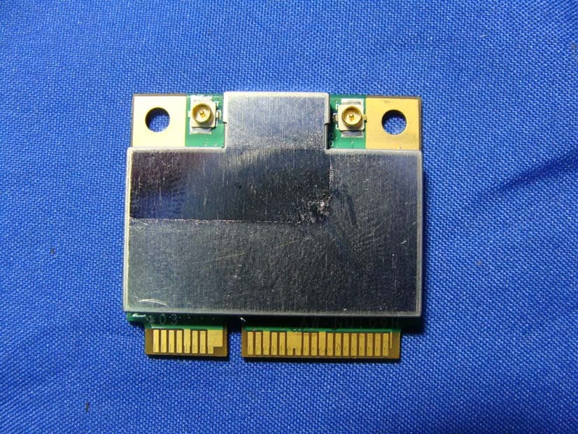
Click to zoom
Application Details
- Equipment Class
- DTS - Digital Transmission System
- Date of Grant
- Aug 26, 2010
- Application Purpose
- Original Equipment
- Date of Application
- Aug 26, 2010
- Equipment Note
- IEEE 802.11b/g/n USB Wireless module
- Frequency Range
- 2422.00000000 - 2452.00000000
- Company
- D-Link Corporation
- Country
- United States
Documents & Files
Document Text
Text extracted from the exhibit documents filed with the FCC. Open a document above to read the original.
Users Manual
AW-NU109H IEEE 802.11n/g/b Wireless USB Module User’s Manual I. Introduction i. Overview Azurewave AW-NU109H USB 2.0 Wireless Module is a highly integrated wireless local area network (WLAN) solution to let users enjoy the digital content through the latest wireless technology without using extra cables and cords. It provides easy-to-use, high performance, cost effective and low power solution. Moreover, AW-NU109H enables compatible high-speed wireless connectivity within home, business and public access wireless networks. Compliant with the IEEE 802.11n/g/b standard, AW-NU109H uses Direct Sequence Spread Spectrum (DSSS), Orthogonal Frequency Division Multiplexing (OFDM), BPSK, QPSK, CCK and QAM baseband modulation technologies. When you are using AW-NU109H, a high level of integration and full implementation of the power management functions specified in the IEEE 802.11 standard can minimize system power requirements. The AW-NU109H 802.11n/g/b Wireless USB Module provides up to 128-bit level of WEP security to your wireless data transfers. It is able to run in the operating systems of Windows XP/Vista in either Infrastructure mode or Ad-Hoc mode. Comparing to previous wireless technology, AW-NU109H got great improvements on speed and range. AW-NU109H is able to double the data rate up to 150Mbps. ii. Features ◎ USB 2.0 Wireless Module ◎ Compliant with IEEE 802.11n/g/b standard ◎1 antenna to support 1 (Transmit) x 1 (Receive) technology ◎ High speed wireless connection up to 150Mbps (For download only, it must connect to the other two Spatial Streams Modulation Access Point) ◎ High performance and low power consumption ◎Enhanced wireless security with 128-bit WEP encryption an WPA iii. Product Review When the USB wireless module is transmitting data through connection, LED indicator will blink. 1. Connection Mode ◎Infrastructure Mode Infrastructure mode needs an access point to establish the network, which can provide wireless accesses within valid range for users to communicate with others or transmit data with a wired network. There are several benefits of Infrastructure networking: √ Roaming: a wireless LAN enabled computer can physically move from the operating range of one access point to the other without losing connection. There is a quick association made between new access point and wireless device as the computer traverses from the coverage of one access point to another. √ Range Extension: each wireless LAN enabled computer within the range of access point can communicate with other wireless LAN enabled computers within the effective range from the access point. √ Wired to wireless LAN connection: the access point will establish a bridge between wireless LAN and other wired counterparts. Infrastructure Mode ◎Ad-hoc Mode The difference between Ad-hoc mode and Infrastructure mode is that Ad-hoc mode does not need the access point or router. When you use this mode, your computer will act as a server within the valid range and connect directly to others in the same LAN workgroup. Ad-hoc Mode It is recommended to choose this mode when there is no access point showed on your wireless network. II. Installation i. System Requirements Before you install AW-NU109H, please make sure your system meets the following requirements. *Desktop or Laptop with USB 1.1/2.0 port *Minimum of 64MB system memory *Operating system: XP/Vista *An optical drive/CD-ROM for utilities and driver installation ii. Hardware Installation 1. Find an available USB 1.1/2.0 port on your desktop or laptop. 2. Plug AW-NU109HWireless USB Module into USB port of desktop or laptop. iii. Operation Range The operating range of AW-NU109H varies from the working environment. However, this device made improvement on speed and range, which also reduced dead spots in coverage area. AW-NU109H is two times wider than previous wireless products. By default, this USB wireless adapter will automatically adjust the data rate. The transmission speed may vary according to the environment. The closer the wireless stations are the better the signal and transmission speed they will receive. iv. Setup: Windows XP OS If your computer is running a Windows operating system, it will automatically detect the AW-NU109H after the system boots up and displays a “Found New Hardware Wizard” window. Please click [Cancel] and proceed with the following steps. 1. Find out the Driver, and launch the Setup Wizard 2. Please wait few seconds for wizard to prepare installation 3. Please select click [Install] to proceed 4. The Wizard is running installation 5. Please wait few seconds for Wizard to setup 6. When it is completed, please click [Finish] 9. When the process is finished, the system will show a message of “Found New Hardware” v. Setup: Windows Vista OS Please follow the steps to complete installation. 1. Launch the setup driver 2. When you see the permission dialogue box, please click [Continue] 3. Now the Wizard is preparing installation 4. Please click [Install] to proceed 5. The system is process installation 8. When the setup is completed, please click [Finish] III. Network Connection i. For Windows XP OS Please see the following steps to setup network connection for Windows XP. 1. Find the network icon on the desktop shortcut and right-click on it. Choose “View Available Wireless networks” 2. You will see several options, please select one and click [Connect] 3. Please wait for few seconds to let system connecting to selected wireless network 4. You may need to type the network key when it is required 5. Now the selected wireless network is connected 6. You can check the connection status by clicking [Status] in the pop-up dialogue 7. Here is the wireless network connection status ii. For Windows Vista OS Following are the instructions to setup wireless connection for Windows Vista. 1. Right-click on the network icon located on desktop shortcut. When you see the dialogue, please click [Connect to a network] 2. Choose wireless network within y…
Text truncated - open the document above for the full version.
External Photos
Report No.: 107272R-RFUSP28V01 Page : 1 of 5 Attachment 2 : EUT Detailed Photographs (1) EUT Photo (2) EUT Photo
ID Label/Location Info
D-Link Corporation FCC ID.: KA2AWNU109HA1 17595 Mt. Herrmann, Fountain Valley, California, United States..Tel : 714-885-6105 FCC ID Label The FCC ID Label will be placed on the equipment as shown in the photograph below.
Internal Photos
Report No.: 107272R-RFUSP28V01 Page : 2 of 5 (3) EUT Photo (4) EUT Photo Report No.: 107272R-RFUSP28V01 Page : 3 of 5 (5) EUT Photo (6) EUT Photo Report No.: 107272R-RFUSP28V01 Page : 4 of 5 (7) EUT Photo (8) EUT Photo Report No.: 107272R-RFUSP28V01 Page : 5 of 5 (9) EUT Photo
Operational Description
Report No. 107272R-RFUSP28V01 Page : 7 of 98 1.2. Operational Description The EUT is an IEEE 802.11b/g/n USB Wireless module with 11 channels. This device provided four kinds of transmitting speed 1, 2, 5.5 and 11Mbps and the device of RF carrier is DBPSK, DQPSK and CCK (IEEE 802.11b). The device provided of eight kinds of transmitting speed 6, 9, 12, 18, 24, 36, 48 and 54Mbps the device of RF carrier is BPSK, QPSK, 16QAM and 64QAM (IEEE 802.11g). The device provided of eight kinds of transmitting speed 7.2,14.4,21.7,28.9,43.3,57.8,65 and 72.2Mbps in 802.11n(20M-BW) mode and 15,30,45.60,90,120,135 and 150 Mbps (40M-BW) the device of RF carrier is BPSK, QPSK, 16QAM and 64QAM (IEEE 802.11n), The IEEE 802.11n is Single In, Single Out” (SISO) technology and two antennas to support 1(Transmit) * 1(Receive) MISO technology. This IEEE 802.11b/g/n USB Wireless module, compliant with IEEE 802.11b and IEEE 802.11g/n, is a high-efficiency Wireless LAN adapter. It allows your computer to connect to a wireless network and to share resources, such as files or printers without being bound to the network wires. Operation in 2.4GHz Direst Sequence Spread Spectrum (DSSS) and Orthogonal Frequency Division Multiplexing (OFDM) radio transmission, the IEEE 802.11b/g/n USB Wireless module Wired Equivalent Protection (WEP) algorithm is used. In addition, its standard compliance ensures that it can communicate with any IEEE 802.11b and IEEE 802.11g/n network.
RF Exposure Info
Report No. 107272R-RFUSP28V01 Page: 1 of 4 RF Exposure Evaluation declaration Product Name : IEEE 802.11b/g/n USB Wireless module Model No. : DAW-NU109H FCC ID : KA2AWNU109HA1 Applicant : D-Link Corporation Address : 17595 Mt. Herrmann, Fountain Valley, California, United States. Date of Receipt : Jul. 19, 2010 Date of Declaration: Jul. 30, 2010 Report No. : 107272R-RFUSP28V01 The declaration results relate only to the samples calculated. The declaration shall not be reproduced except in full without the written approval of QuieTek Corporation. This report must not be used to claim product endorsement by NVLAP any agency of the U.S. Government Report No. 107272R-RFUSP28V01 Page: 2 of 4 1. RF Exposure Evaluation 1.1. Limits According to FCC 1.1310: The criteria listed in the following table shall be used to evaluate the environment impact of human exposure to radio frequency (RF) radiation as specified in 1.1307(b) LIMITS FOR MAXIMUM PERMISSIBLE EXPOSURE (MPE) Frequency Range (MHz) Electric Field Strength (V/m) Magnetic Field Strength (A/m) Power Density (mW/cm 2 ) Average Time (Minutes) (A) Limits for Occupational/ Control Exposures 300-1500 -- -- F/300 6 1500-100,000 -- -- 5 6 (B) Limits for General Population/ Uncontrolled Exposures 300-1500 -- -- F/1500 6 1500-100,000 -- -- 1 30 F= Frequency in MHz Friis Formula Friis transmission formula: Pd = (Pout*G)/(4*pi*r 2 ) Where Pd = power density in mW/cm 2 Pout = output power to antenna in mW G = gain of antenna in linear scale Pi = 3.1416 R = distance between observation point and center of the radiator in cm Pd id the limit of MPE, 1 mW/cm 2 . If we know the maximum gain of the antenna and the total power input to the antenna, through the calculation, we will know the distance r where the MPE limit is reached. 1.2. Test Procedure Software provided by client enabled the EUT to transmit and receive data at lowest, middle and highest channel individually. The temperature and related humidity: 18°Cand 78% RH. Report No. 107272R-RFUSP28V01 Page: 3 of 4 1.3. Test Result of RF Exposure Evaluation Product : IEEE 802.11b/g/n USB Wireless module Test Item : RF Exposure Evaluation Test Site : No.3 OATS Antenna Gain Antenna Gain: The maximum Gain measured in fully anechoic chamber is 3.35 dBi in logarithm scale. 802.11b - 1Mbps Output Power Into Antenna & RF Exposure Evaluation Distance (3.35 dBi): Channel Frequency (MHz) Output Power to Antenna (mW) Power Density at R = 20 cm (mW/cm2) 01 2412.00 72.4436 0.031170 06 2437.00 71.1214 0.030601 11 2462.00 65.0130 0.027972 802.11g - 6Mbps Output Power Into Antenna & RF Exposure Evaluation Distance (3.35 dBi): Channel Frequency (MHz) Output Power to Antenna (mW) Power Density at R = 20 cm (mW/cm2) 01 2412.00 232.8091 0.100168 06 2437.00 229.0868 0.098567 11 2462.00 213.7962 0.091988 802.11n - 20BW Output Power Into Antenna & RF Exposure Evaluation Distance (3.35 dBi): Channel Frequency (MHz) Output Power to Antenna (mW) Power Density at R = 20 cm (mW/cm2) 01 2412.00 155.9553 0.067101 06 2437.00 154.8817 0.066639 11 2462.00 151.3561 0.065122 Report No. 107272R-RFUSP28V01 Page: 4 of 4 802.11n - 40BW Output Power Into Antenna & RF Exposure Evaluation Distance (3.35 dBi): Channel Frequency (MHz) Output Power to Antenna (mW) Power Density at R = 20 cm (mW/cm2) 01 2422 177.8279 0.076512 04 2437 178.2379 0.076689 07 2452 177.0109 0.076161
Test Report
Report No. 107272R-RFUSP37V02 Page : 1 of 27 Test Report Product Name IEEE 802.11b/g/n USB Wireless module Model No DAW-NU109H FCC ID. DoC Applicant D-Link Corporation Address 17595 Mt. Herrmann, Fountain Valley, California, United States. Date of Receipt Jul. 19, 2010 Issue Date Jul. 30, 2010 Report No. 107272R-RFUSP37V02 Report Version V1.0 The test results relate only to the samples tested. The test report shall not be reproduced except in full without the written approval of QuieTek Corporation. This report must not be used to claim product endorsement by NVLAP any agency of the U.S. Government Report No. 107272R-RFUSP37V02 Page : 2 of 27 Test Report Certification Issue Date: Jul. 30, 2010 Report No.: 107272R-RFUSP37V02 Product Name IEEE 802.11b/g/n USB Wireless module Applicant D-Link Corporation Address 17595 Mt. Herrmann, Fountain Valley, California, United States. Manufacturer AzureWave Technologies, Inc. Model No. DAW-NU109H FCC ID. DoC EUT Rated Voltage DC 3.3 EUT Test Voltage AC 120V / 60Hz Trade Name D-Link Applicable Standard FCC CFR Title 47 Part 15 Subpart B: 2009 ANSI C63.4: 2003 Test Result Complied The test results relate only to the samples tested. The test report shall not be reproduced except in full without the written approval of QuieTek Corporation. This report must not be used to claim product endorsement by NVLAP any agency of the U.S. Government Documented By : ( Adm. Specialist /Joanne Lin ) Tested By : (Engineer / Joe Guo ) Approved By : ( Manager / Vincent Lin ) Accredited by NIST (NVLAP) NVLAP Lab Code: 200533-0 Report No. 107272R-RFUSP37V02 Page : 3 of 27 TABLE OF CONTENTS Description Page 1. GENERAL INFORMATION .....................................................................................................4 1.1. EUT Description............................................................................................................................4 1.2. Tested System Details....................................................................................................................6 1.3. Configuration of Tested System ....................................................................................................7 1.4. EUT Exercise Software .................................................................................................................7 1.5. Test Facility ...................................................................................................................................8 2. Conducted Emission....................................................................................................................9 2.1. Test Equipment..............................................................................................................................9 2.2. Test Setup ......................................................................................................................................9 2.3. Limits ..........................................................................................................................................10 2.4. Test Procedure .............................................................................................................................10 2.5. Uncertainty ..................................................................................................................................10 2.6. Test Result of Conducted Emission.............................................................................................11 3. Radiated Emission .....................................................................................................................13 3.1. Test Equipment............................................................................................................................13 3.2. Test Setup ....................................................................................................................................14 3.3. Limits ..........................................................................................................................................15 3.4. Test Procedure .............................................................................................................................15 3.5. Uncertainty ..................................................................................................................................16 3.6. Test Result of Radiated Emission................................................................................................17 4. EMI Reduction Method During Compliance Testing ............................................................25 Attachment 1: EUT Test Photographs Attachment 2: EUT Detailed Photographs Report No. 107272R-RFUSP37V02 Page : 4 of 27 1. GENERAL INFORMATION 1.1. EUT Description Product Name IEEE 802.11b/g/n USB Wireless module Trade Name D-Link Model No. DAW-NU109H FCC ID. DoC Frequency Range 2412-2462MHz for 802.11b/g/n-20BW, 2422-2452Mhz for 802.11n-40BW Number of Channels 802.11b/g/n-20MHz: 11, n-40MHz: 7 Data Speed 802.11b: 1-11Mbps, 802.11g: 6-54Mbps, 802.11n: 7.2-150Mbps Type of Modulation WLAN: 802.11b:DSSS DBPSK, DQPSK, CCK 802.11g/n:OFDM BPSK, QPSK, 16QAM, 64QAM Antenna Type PIFA Antenna Gain Refer to the table “Antenna List” Channel Control Auto Antenna List No. Manufacturer Part No. Peak Gain 1 FAVORTRON E773700193 (MAIN) E773700194 (AUX) 3.35dBi for 2.4GHz Report No. 107272R-RFUSP37V02 Page : 5 of 27 802.11b/g/n-20MHz Center Frequency of Each Channel: Channel Frequency Channel FrequencyChannel FrequencyChannel Frequency Channel 01: 2412 MHz Channel 02: 2417 MHz Channel 03: 2422 MHz Channel 04: 2427 MHz Channel 05: 2432 MHz Channel 06: 2437 MHz Channel 07: 2442 MHz Channel 08: 2447 MHz Channel 09: 2452 MHz Channel 10: 2457 MHz Channel 11: 2462 MHz 802.11n-40MHz Center Frequency of Each Channel: Channel Frequency Channel FrequencyChannel FrequencyChannel Frequency Channel 01: 2422 MHz Channel 02: 2427 MHz Channel 03: 2432 MH…
Text truncated - open the document above for the full version.
Test Report
Report No. 107272R-RFUSP28V01 Page : 1 of 98 Test Report Product Name IEEE 802.11b/g/n USB Wireless module Model No DAW-NU109H FCC ID. KA2AWNU109HA1 Applicant D-Link Corporation Address 17595 Mt. Herrmann, Fountain Valley, California, United States. Date of Receipt Jul. 19, 2010 Issue Date Jul. 30, 2010 Report No. 107272R-RFUSP28V01 Report Version V1.0 The test results relate only to the samples tested. The test report shall not be reproduced except in full without the written approval of QuieTek Corporation. This report must not be used to claim product endorsement by NVLAP any agency of the U.S. Government Report No. 107272R-RFUSP28V01 Page : 2 of 98 Test Report Certification Issue Date: Jul. 30, 2010 Report No.: 107272R-RFUSP28V01 Product Name IEEE 802.11b/g/n USB Wireless module Applicant D-Link Corporation Address 17595 Mt. Herrmann, Fountain Valley, California, United States. Manufacturer AzureWave Technologies, Inc. Model No. DAW-NU109H EUT Rated Voltage DC 3.3V EUT testing Voltage AC 120V/60Hz Trade Name D-Link Applicable Standard FCC CFR Title 47 Part 15 Subpart C: 2009 ANSI C63.4: 2003 Test Result Complied The test results relate only to the samples tested. The test report shall not be reproduced except in full without the written approval of QuieTek Corporation. This report must not be used to claim product endorsement by NVLAP any agency of the U.S. Government Documented By : ( Adm. Specialist / Joanne Lin ) Tested By : (Engineer / Joe Guo ) Approved By : ( Manager / Vincent Lin) Accredited by NIST (NVLAP) NVLAP Lab Code: 200533-0 Report No. 107272R-RFUSP28V01 Page : 3 of 98 TABLE OF CONTENTS Description Page 1. GENERAL INFORMATION .....................................................................................................5 1.1. EUT Description............................................................................................................................5 1.2. Operational Description ................................................................................................................7 1.3. Tested System Details....................................................................................................................8 1.4. Configuration of Tested System ....................................................................................................9 1.5. EUT Exercise Software .................................................................................................................9 1.6. Test Facility .................................................................................................................................10 2. Conducted Emission.................................................................................................................. 11 2.1. Test Equipment............................................................................................................................11 2.2. Test Setup ....................................................................................................................................11 2.3. Limits ..........................................................................................................................................12 2.4. Test Procedure .............................................................................................................................12 2.5. Uncertainty ..................................................................................................................................12 2.6. Test Result of Conducted Emission.............................................................................................13 3. Peak Power Output ...................................................................................................................15 3.1. Test Equipment............................................................................................................................15 3.2. Test Setup ....................................................................................................................................15 3.3. Limits ..........................................................................................................................................15 3.4. Test Procedure .............................................................................................................................15 3.5. Uncertainty ..................................................................................................................................15 3.6. Test Result of Peak Power Output...............................................................................................16 4. Radiated Emission .....................................................................................................................20 4.1. Test Equipment............................................................................................................................20 4.2. Test Setup ....................................................................................................................................21 4.3. Limits ..........................................................................................................................................22 4.4. Test Procedure .............................................................................................................................23 4.5. Uncertainty ..................................................................................................................................23 4.6. Test Result of Radiated Emission................................................................................................24 5. RF antenna conducted test........................................................................................................40 5.1. Test Equipment............................................................................................................................40 5.2. Test Se…
Text truncated - open the document above for the full version.
Test Report
Report No. 107272R-RFUSP28V01 Page: 67 of 98 Product : IEEE 802.11b/g/n USB Wireless module Test Item : Band Edge Data Test Site : No.3 OATS Test Mode : Mode 4: Transmit (802.11n MCS0 15Mbps 40M-BW) (2452MHz) Fundamental Filed Strength Antenna Pole Frequency [MHz] Correction Factor [dB/m] Reading Level [dBuV] Emission Level [dBuV/m] Detector Horizontal 2452 31.944 59.18 91.124 Peak Horizontal 2452 31.944 35.67 67.614 Average Vertical 2452 31.222 70.47 101.692 Peak Vertical 2452 31.222 43.25 74.472 Average Note: 1:Spectrum Analyzer setting: Peak detector: RBW=1MHz, VBW=1MHz Average detector: RBW=1MHz, VBW=10Hz Band Edge Test Data Antenna Pole Test Frequency (MHz) Fundamental (dBuV/m) Δ (dB) Band Edge Field Strength (dBuV/m) Detector Horizontal 2483.5 91.124 35.394 55.73 Peak Horizontal 2483.5 67.614 25.309 42.305 Average Vertical 2483.5 101.692 35.394 66.298 Peak Vertical 2483.5 74.472 25.309 49.163 Average Note: The Band Edge Field Strength was calculated using the Fundamental and Conducted Band Edge measurements per the Marker-Delta Method with the following formula: Band Edge field Strength = F - Δ F = Fundamental field Strength (Peak or Average) Δ = Conducted Band Edge Delta (Peak or Average) Report No. 107272R-RFUSP28V01 Page: 68 of 98 Peak Detector of conducted Band Edge Delta Average Detector of conducted Band Edge Delta Report No. 107272R-RFUSP28V01 Page: 69 of 98 7. Occupied Bandwidth 7.1. Test Equipment Equipment Manufacturer Model No./Serial No. Last Cal. Spectrum Analyzer R&S FSP40 / 100170 Jun, 2010 Spectrum Analyzer Agilent E4407B / US39440758 Jun, 2010 X Spectrum Analyzer Agilent N9010A / MY48030495 Apr., 2010 8-WAY Power Divider JFW 50PD-647 / 526770 0916 Apr., 2010 Note: 1. All equipments are calibrated with traceable calibrations. Each calibration is traceable to the national or international standards. 2. The test instruments marked with “X” are used to measure the final test results. 3. The power combiner is used for measure 11n mode. 7.2. Test Setup 7.3. Limits The minimum bandwidth shall be at least 500 kHz. 7.4. Test Procedure The EUT was setup according to ANSI C63.4, 2003; tested according to DTS test procedure of Mar. 2005 KDB558074 for compliance to FCC 47CFR 15.247 requirements. Set RBW = 100 kHz, Span greater than RBW. 7.5. Uncertainty ± 150Hz SMA Connector EUT Spectrum Analyzer RF Cable Report No. 107272R-RFUSP28V01 Page: 70 of 98 7.6. Test Result of Occupied Bandwidth Product : IEEE 802.11b/g/n USB Wireless module Test Item : Occupied Bandwidth Data Test Site : No.3 OATS Test Mode : Mode 1: Transmit (802.11b 1Mbps) (2412MHz) Channel No. Frequency (MHz) Measurement Level (kHz) Required Limit (kHz) Result 1 2412.00 7600 >500 Pass Figure Channel 1: Report No. 107272R-RFUSP28V01 Page: 71 of 98 Product : IEEE 802.11b/g/n USB Wireless module Test Item : Occupied Bandwidth Data Test Site : No.3 OATS Test Mode : Mode 1: Transmit (802.11b 1Mbps) (2437MHz) Channel No. Frequency (MHz) Measurement Level (kHz) Required Limit (kHz) Result 6 2437.00 7650 >500 Pass Figure Channel 6: Report No. 107272R-RFUSP28V01 Page: 72 of 98 Product : IEEE 802.11b/g/n USB Wireless module Test Item : Occupied Bandwidth Data Test Site : No.3 OATS Test Mode : Mode 1: Transmit (802.11b 1Mbps) (2462MHz) Channel No. Frequency (MHz) Measurement Level (kHz) Required Limit (kHz) Result 11 2462.00 7150 >500 Pass Figure Channel 11: Report No. 107272R-RFUSP28V01 Page: 73 of 98 Product : IEEE 802.11b/g/n USB Wireless module Test Item : Occupied Bandwidth Data Test Site : No.3 OATS Test Mode : Mode 2: Transmit (802.11g 6Mbps) (2412MHz) Channel No. Frequency (MHz) Measurement Level (kHz) Required Limit (kHz) Result 1 2412.00 15350 >500 Pass Figure Channel 1: Report No. 107272R-RFUSP28V01 Page: 74 of 98 Product : IEEE 802.11b/g/n USB Wireless module Test Item : Occupied Bandwidth Data Test Site : No.3 OATS Test Mode : Mode 2: Transmit (802.11g 6Mbps) (2437MHz) Channel No. Frequency (MHz) Measurement Level (kHz) Required Limit (kHz) Result 6 2437.00 15200 >500 Pass Figure Channel 6: Report No. 107272R-RFUSP28V01 Page: 75 of 98 Product : IEEE 802.11b/g/n USB Wireless module Test Item : Occupied Bandwidth Data Test Site : No.3 OATS Test Mode : Mode 2: Transmit (802.11g 6Mbps) (2462MHz) Channel No. Frequency (MHz) Measurement Level (kHz) Required Limit (kHz) Result 11 2462.00 15200 >500 Pass Figure Channel 11: Report No. 107272R-RFUSP28V01 Page: 76 of 98 Product : IEEE 802.11b/g/n USB Wireless module Test Item : Occupied Bandwidth Data Test Site : No.3 OATS Test Mode : Mode 3: Transmit (802.11n MCS0 7.2Mbps 20M-BW) (2412MHz) Channel No. Frequency (MHz) Measurement Level (kHz) Required Limit (kHz) Result 1 2412.00 16950 >500 Pass Figure Channel 1: Report No. 107272R-RFUSP28V01 Page: 77 of 98 Product : IEEE 802.11b/g/n USB Wireless module Test Item : Occupied Bandwidth Data Test Site : No.3 OATS Test Mode : Mode 3: Transmit (802.11n MCS0 7.2Mbps 20M-BW) (2437MHz) Channel No. Frequency (MHz) Measurement Level (kHz) Required Limit (kHz) Result 6 2437.00 16700 >500 Pass Figure Channel 6: Report No. 107272R-RFUSP28V01 Page: 78 of 98 Product : IEEE 802.11b/g/n USB Wireless module Test Item : Occupied Bandwidth Data Test Site : No.3 OATS Test Mode : Mode 3: Transmit (802.11n MCS0 7.2Mbps 20M-BW) (2462MHz) Channel No. Frequency (MHz) Measurement Level (kHz) Required Limit (kHz) Result 11 2462.00 17350 >500 Pass Figure Channel 11: Report No. 107272R-RFUSP28V01 Page: 79 of 98 Product : IEEE 802.11b/g/n USB Wireless module Test Item : Occupied Bandwidth Data Test Site : No.3 OATS Test Mode : Mode 4: Transmit (802.11n MCS0 15Mbps 40M-BW) (2422MHz) Channel No. Frequency (MHz) Measurement Level (kHz) Required Limit (kHz) Result 1 2422.00 36500 >500 Pass Figure Channel 1: Report No. 107272R-RFUSP28V01 Page: 80 of 98 Product : IEEE 802.11b/g/n USB Wireless module Test Item : Occupied Bandwidth Data Test Site : No.3 OATS Test Mode : Mode 4: Transmit (802.11n MCS0 15Mbps 40M-BW) (2437MHz) Channel No. Frequency (MHz) Measuremen…
Text truncated - open the document above for the full version.
Test Report
Report No. 107272R-RFUSP28V01 Page: 95 of 98 Product : IEEE 802.11b/g/n USB Wireless module Test Item : Power Density Data Test Site : No.3 OATS Test Mode : Mode 4: Transmit (802.11n MCS0 15Mbps 40M-BW) (2452MHz) Channel No. Frequency (MHz) Measurement Level (dBm) Required Limit (dBm) Result 7 2452.00 -14.891 < 8dBm Pass Figure Channel 7: Report No. 107272R-RFUSP28V01 Page: 96 of 98 9. EMI Reduction Method During Compliance Testing No modification was made during testing.
Test Setup Photos
Report No.: 107272R-RFUSP28V01 Page : 1 of 3 Attachment 1: EUT Test Setup Photograp…
Text truncated - open the document above for the full version.
Contact Information
Applicant
Brett Adair(General Counsel)
Technical Contact
QuieTek CorporationVincent Lin
[email protected]886-2-8601-3788
No. 5-22, Ruei-Shu Valley,Ruei-Ping · Taiwan
Test Firm
DEKRA TESTING AND CERTIFICATION CO., LTD. LinKouMirenda Liao
Technical Specifications
| # | Rule Parts | Frequency Range | Power Output |
|---|---|---|---|
| 2 | 15C | 2.42 GHz - 2.45 GHz | 178.20 mW |
Other Applications from D-Link Corporation

KA2CS6012A1
Jul 07, 20262K Fixed Indoor Cloud Camera, 2K Fixed Indoor Wi-Fi Camera
Equipment Class
DTS - Digital Transmission SystemKA2AE65UA1
Mar 02, 2026Wi-Fi 7 BE6500 USB 3.0 Dongle
Equipment Class
NII - Unlicensed National Information Infrastructure TXKA2APE9560A1
Nov 17, 2025BE9500 Celling mount Access Point
Equipment Class
6ID - 15E 6 GHz Low Power Indoor Access PointKA2AX9UA1
Dec 04, 2024AX900 Wi-Fi 6 USB Adapter, Wi-Fi 6 AX900 USB 2.0 Dongle
Equipment Class
DSS - Part 15 Spread Spectrum TransmitterKA2AC13UA1
Dec 04, 2024AC1300 Wi-Fi 5 USB Adapter, Wi-Fi 5 AC1300 USB 2.0 Dongle
Equipment Class
DTS - Digital Transmission System