KA2CS800LA1Wi-Fi Baby Camera Junior, Wi-Fi Baby Camera Jr.
D-Link Corporation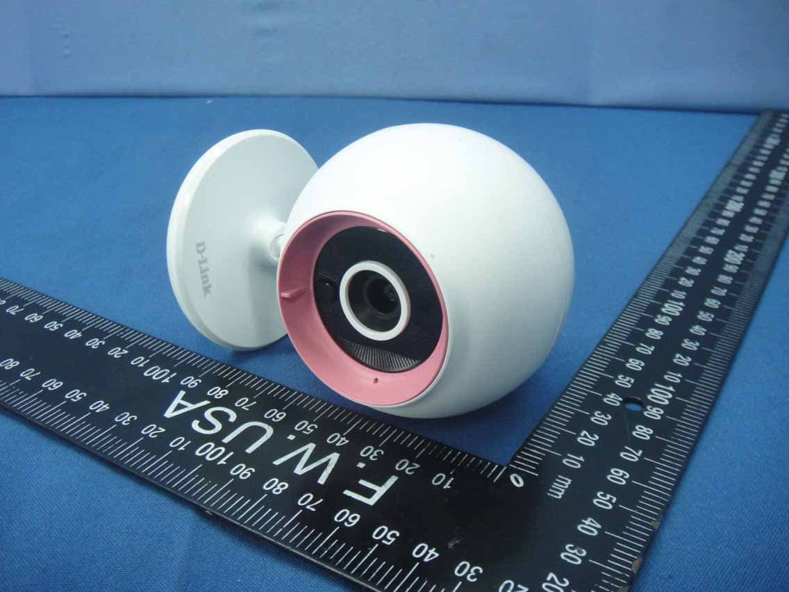
Click to zoom
Application Details
- Equipment Class
- DTS - Digital Transmission System
- Date of Grant
- Jun 26, 2014
- Application Purpose
- Original Equipment
- Date of Application
- Jun 26, 2014
- Equipment Note
- Wi-Fi Baby Camera Junior, Wi-Fi Baby Camera Jr.
- Frequency Range
- 2412.00000000 - 2462.00000000
- Company
- D-Link Corporation
- Country
- United States
Documents & Files
Document Text
Text extracted from the exhibit documents filed with the FCC. Open a document above to read the original.
Users Manual
Wi-Fi Baby Camera Jr. DCS-700L Quick Installation Guide Краткое руководство по установке Guía de Instalación Rápida Guia de Instalação Rápida 快速安裝指南 Petunjuk Pemasangan Cepat クイックインストールガイド DCS-700L 3 English • Please save this guide for future reference. • Please read these instructions before using your product. • Do not cover the ventilation holes. • Do not cover this product with a blanket. • Do not allow children to play with this product. • Do not place this product near water or other liquids, such as near a sink, shower, or bathtub. • Do not attempt to open or disassemble this product. • Cleaning: Clean the camera with a dry cloth only; do not allow the camera to get wet. • Strangulation Hazard: Keep this product and any attached cords at least 3 feet out of reach of a child and out of your baby's crib/cot. • This product is not a replacement for responsible adult supervision. Before you get started... Check to make sure your box has these items: 1 Wi-Fi Baby Camera Jr. (DCS-700L) Power adapter Additional accent rings Wall mount kit If any of these items are missing from your packaging, contact your reseller. DCS-700L 4 English You can use the included power adapter, or you can use a portable USB battery(not included) that can supply 5 V / 2 A of power. Plug in your camera, and wait until the Power LED turns green. 2 Search for the free mydlink Baby Camera Monitor on the App Store or Google Play, then download and run the app. The app will guide you step by step through the setup process. Download and run the free mydlink Baby Camera Monitor app to set up your camera. 3 DCS-700L 5 English Your Wi-Fi Baby Camera Jr. Front View Back View Microphone Front Accent Ring Camera Base Light Sensor Camera Lens Night Vision Light (IR) Speaker MicroUSB Power Port Cloud/Direct Mode LED Reset Button Power LED Direct Button DCS-700L 6 English Mounting your camera (optional) • Use a 6mm drill bit to drill two holes 36mm apart, and at least 30mm deep. 36mm 30mm • Place the mounting holes on the base of the camera over the screws as shown, then slide the camera down to mount the camera. FCC ID: KA2CS800L A1 IC: 4216A-CS80 0LA1 CAN ICES-3 (B) /NMB-3(B) Model: DCS-800LA1 DCS-8 0 0 L • Use a mallet to insert the wall anchors into the holes. • Screw the included screws into the wall anchors. DCS-700L 7 English How do I change the accent ring? • Rotate the accent ring counterclockwise, then lift it off. Put the new accent ring on, then rotate it clockwise until it clicks into place. How do I select a different lullaby? • You can change the lullaby used in the mydlink Baby Camera Monitor app. There’s a white haze on my camera video when I use night vision mode. • The night vision light on the Wi-Fi Baby Camera may be reflecting off a nearby surface. Try repositioning and aiming the camera. I started the mydlink Baby Camera Monitor app, but I can’t find my camera. • Make sure your camera is turned on and receiving power. • If you have set up your camera before, make sure your smartphone or tablet is connected to the same router as your camera. • If you are setting up a new camera or are using the camera away from home, make sure your smartphone or tablet is connected to the camera’s Wi-Fi network. • The Wi-Fi network name should be [myBabyCam-XXXX], where XXXX is a 4-digit code. You can find it printed on a label on the bottom of your camera. • The Wi-Fi password is printed on a label on the bottom of your camera. • You can also find your camera’s Wi-Fi network details on a label attached to the back of this guide. • If you still can’t find your camera, reset your camera by pressing its reset button for 10 seconds while it is powered on. Troubleshooting DCS-700L 8 English You can find software updates and user documentation on the D-Link website. Tech Support for customers in Australia: Tel: 1300-766-868 24/7 Technical Support Web: http://www.dlink.com.au E-mail: [email protected] India: Tel: +91-832-2856000 Toll Free 1800-233-0000 Web: www.dlink.co.in E-Mail: [email protected] Singapore, Thailand, Indonesia, Malaysia, Philippines, Vietnam: Singapore - www.dlink.com.sg Thailand - www.dlink.co.th Indonesia - www.dlink.co.id Malaysia - www.dlink.com.my Philippines - www.dlink.com.ph Vietnam - www.dlink.com.vn Korea: Tel : +82-2-2028-1810 Monday to Friday 9:00am to 6:00pm Web : http://d-link.co.kr E-mail : [email protected] New Zealand: Tel: 0800-900-900 24/7 Technical Support Web: http://www.dlink.co.nz E-mail: [email protected] South Africa and Sub Sahara Region: Tel: +27 12 661 2025 08600 DLINK (for South Africa only) Monday to Friday 8:30am to 9:00pm South Africa Time Web: http://www.d-link.co.za E-mail: [email protected] D-Link Middle East - Dubai, U.A.E. Plot No. S31102, Jebel Ali Free Zone South, P.O.Box 18224, Dubai, U.A.E. Tel: +971-4-8809022 Fax: +971-4-8809066 / 8809069 Technical Support: +971-4-8809033 General Inquiries: [email protected] Tech Support: [email protected] Egypt 1, Makram Ebeid Street - City Lights Building Nasrcity - Cairo, Egypt Floor 6, office C2 Tel.: +2 02 26718375 - +2 02 26717280 Technical Support: +2 02 26738470 General Inquiries: [email protected] Tech Support: [email protected] Kingdom of Saudi Arabia Office # 84 , Al Khaleej Building ( Mujamathu Al-Khaleej) Opp. King Fahd Road, Olaya Riyadh - Saudi Arabia Tel: +966 1121 70008 Technical Support: +966 1121 70009 General Inquiries: info.sa@ dlinkmea.com Tech Support: support.sa@ dlinkmea.com Pakistan Islamabad Office: 61-A, Jinnah Avenue, Blue Area, Suite # 11, EBC, Saudi Pak Tower, Islamabad - Pakistan Tel.: +92-51-2800397, 2800398 Fax: +92-51-2800399 Karachi Office: D-147/1, KDA Scheme # 1, Opposite Mudassir Park, Karsaz Road, Karachi – Pakistan Phone: +92-21-34548158, 34326649 Fax: +92-21-4375727 Technical Support: +92-21-34548310, 34305069 General Inquiries: [email protected] Tech Support: [email protected] Technical Support DCS-700L 9 English 073-796-2797 Technical Support Iran Unit …
Text truncated - open the document above for the full version.
Users Manual
Wi-Fi Baby Camera Junior DCS-800L Quick Installation Guide Краткое руководство по установке Guía de Instalación Rápida Guia de Instalação Rápida 快速安裝指南 Petunjuk Pemasangan Cepat クイックインストールガイド DCS-800L 3 English • Please save this guide for future reference. • Please read these instructions before using your product. • Do not cover the ventilation holes. • Do not cover this product with a blanket. • Do not allow children to play with this product. • Do not place this product near water or other liquids, such as near a sink, shower, or bathtub. • Do not attempt to open or disassemble this product. • Cleaning: Clean the camera with a dry cloth only; do not allow the camera to get wet. • Strangulation Hazard: Keep this product and any attached cords at least 3 feet out of reach of a child and out of your baby's crib/cot. • This product is not a replacement for responsible adult supervision. Before you get started... Check to make sure your box has these items: 1 Wi-Fi Baby Camera Junior (DCS-800L) Power adapter Additional accent rings Wall mount kit If any of these items are missing from your packaging, contact your reseller. DCS-800L 4 English You can use the included power adapter, or you can use a portable USB battery(not included) that can supply 5 V / 2 A of power. Plug in your camera, and wait until the Power LED turns green. 2 Search for the free mydlink Baby Camera Monitor on the App Store or Google Play, then download and run the app. The app will guide you step by step through the setup process. Download and run the free mydlink Baby Camera Monitor app to set up your camera. 3 DCS-800L 5 English Your Wi-Fi Baby Camera Junior Front View Back View Microphone Front Accent Ring Camera Base Light Sensor Camera Lens Night Vision Light (IR) Speaker MicroUSB Power Port Cloud/Direct Mode LED Reset Button Power LED Direct Button DCS-800L 6 English Mounting your camera (optional) • Use a 6mm drill bit to drill two holes 36mm apart, and at least 30mm deep. 36mm 30mm • Place the mounting holes on the base of the camera over the screws as shown, then slide the camera down to mount the camera. FCC ID: KA2CS800L A1 IC: 4216A-CS80 0LA1 CAN ICES-3 (B) /NMB-3(B) Model: DCS-800LA1 DCS-8 0 0 L • Use a mallet to insert the wall anchors into the holes. • Screw the included screws into the wall anchors. DCS-800L 7 English How do I change the accent ring? • Rotate the accent ring counterclockwise, then lift it off. Put the new accent ring on, then rotate it clockwise until it clicks into place. How do I select a different lullaby? • You can change the lullaby used in the mydlink Baby Camera Monitor app. There’s a white haze on my camera video when I use night vision mode. • The night vision light on the Wi-Fi Baby Camera may be reflecting off a nearby surface. Try repositioning and aiming the camera. I started the mydlink Baby Camera Monitor app, but I can’t find my camera. • Make sure your camera is turned on and receiving power. • If you have set up your camera before, make sure your smartphone or tablet is connected to the same router as your camera. • If you are setting up a new camera or are using the camera away from home, make sure your smartphone or tablet is connected to the camera’s Wi-Fi network. • The Wi-Fi network name should be [myBabyCam-XXXX], where XXXX is a 4-digit code. You can find it printed on a label on the bottom of your camera. • The Wi-Fi password is printed on a label on the bottom of your camera. • You can also find your camera’s Wi-Fi network details on a label attached to the back of this guide. • If you still can’t find your camera, reset your camera by pressing its reset button for 10 seconds while it is powered on. Troubleshooting DCS-800L 8 English You can find software updates and user documentation on the D-Link website. Tech Support for customers in Australia: Tel: 1300-766-868 24/7 Technical Support Web: http://www.dlink.com.au E-mail: [email protected] India: Tel: +91-832-2856000 Toll Free 1800-233-0000 Web: www.dlink.co.in E-Mail: [email protected] Singapore, Thailand, Indonesia, Malaysia, Philippines, Vietnam: Singapore - www.dlink.com.sg Thailand - www.dlink.co.th Indonesia - www.dlink.co.id Malaysia - www.dlink.com.my Philippines - www.dlink.com.ph Vietnam - www.dlink.com.vn Korea: Tel : +82-2-2028-1810 Monday to Friday 9:00am to 6:00pm Web : http://d-link.co.kr E-mail : [email protected] New Zealand: Tel: 0800-900-900 24/7 Technical Support Web: http://www.dlink.co.nz E-mail: [email protected] South Africa and Sub Sahara Region: Tel: +27 12 661 2025 08600 DLINK (for South Africa only) Monday to Friday 8:30am to 9:00pm South Africa Time Web: http://www.d-link.co.za E-mail: [email protected] D-Link Middle East - Dubai, U.A.E. Plot No. S31102, Jebel Ali Free Zone South, P.O.Box 18224, Dubai, U.A.E. Tel: +971-4-8809022 Fax: +971-4-8809066 / 8809069 Technical Support: +971-4-8809033 General Inquiries: [email protected] Tech Support: [email protected] Egypt 1, Makram Ebeid Street - City Lights Building Nasrcity - Cairo, Egypt Floor 6, office C2 Tel.: +2 02 26718375 - +2 02 26717280 Technical Support: +2 02 26738470 General Inquiries: [email protected] Tech Support: [email protected] Kingdom of Saudi Arabia Office # 84 , Al Khaleej Building ( Mujamathu Al-Khaleej) Opp. King Fahd Road, Olaya Riyadh - Saudi Arabia Tel: +966 1121 70008 Technical Support: +966 1121 70009 General Inquiries: info.sa@ dlinkmea.com Tech Support: support.sa@ dlinkmea.com Pakistan Islamabad Office: 61-A, Jinnah Avenue, Blue Area, Suite # 11, EBC, Saudi Pak Tower, Islamabad - Pakistan Tel.: +92-51-2800397, 2800398 Fax: +92-51-2800399 Karachi Office: D-147/1, KDA Scheme # 1, Opposite Mudassir Park, Karsaz Road, Karachi – Pakistan Phone: +92-21-34548158, 34326649 Fax: +92-21-4375727 Technical Support: +92-21-34548310, 34305069 General Inquiries: [email protected] Tech Support: [email protected] Technical Support DCS-800L 9 English 073-796-2797 Technical Support I…
Text truncated - open the document above for the full version.
External Photos
Report No.: 140515E01 Page No. 1 / 28 CONSTRUCTION PHOTOS OF EUT Model No.: DCS-800L Report No.: 140515E01 Page No. 2 / 28 Report No.: 140515E01 Page No. 3 / 28 Report No.: 140515E01 Page No. 4 / 28 Report No.: 140515E01 Page No. 13 / 28 Model No.: DCS-700L Report No.: 140515E01 Page No. 14 / 28 Report No.: 140515E01 Page No. 15 / 28 Report No.: 140515E01 Page No. 24 / 28 Adapter 1: Brand: APD, Model No.: WA-08B05R (US Plug) Report No.: 140515E01 Page No. 25 / 28 Report No.: 140515E01 Page No. 26 / 28 Report No.: 140515E01 Page No. 27 / 28 Adapter 2: Brand: AMIGO, Model No.: AMS1-0501200FU Report No.: 140515E01 Page No. 28 / 28
ID Label/Location Info
FCC ID: KA2CS800LA1 LABEL LOCATION The label will be permanently affixed at a conspicuous location on the device. Label Here FCC ID: KA2CS800LA1 LABEL LOCATION The label will be permanently affixed at a conspicuous location on the device. Label Here
Internal Photos
Report No.: 140515E01 Page No. 5 / 28 Model No.: DCS-800L Report No.: 140515E01 Page No. 6 / 28 Report No.: 140515E01 Page No. 7 / 28 Report No.: 140515E01 Page No. 8 / 28 Report No.: 140515E01 Page No. 9 / 28 Report No.: 140515E01 Page No. 10 / 28 Report No.: 140515E01 Page No. 11 / 28 Report No.: 140515E01 Page No. 12 / 28 Report No.: 140515E01 Page No. 16 / 28 Model No.: DCS-700L Report No.: 140515E01 Page No. 17 / 28 Report No.: 140515E01 Page No. 18 / 28 Report No.: 140515E01 Page No. 19 / 28 Report No.: 140515E01 Page No. 20 / 28 Report No.: 140515E01 Page No. 21 / 28 Report No.: 140515E01 Page No. 22 / 28 Report No.: 140515E01 Page No. 23 / 28
RF Exposure Info
Report No.: SA140515E01 1 of 6 Report Format Version 5.0.0 RF EXPOSURE REPORT REPORT NO.: SA140515E01 MODEL NO.: DCS-800L, DCS-800LA1, DCS-700L, DCS-700LA1 FCC ID: KA2CS800LA1 RECEIVED: May 15, 2014 TESTED: May 19, 2014 ISSUED: June 24, 2014 APPLICANT: D-Link Corporation ADDRESS: No.289, Sinhu 3rd Rd., Neihu District, Taipei City 114, Taiwan, R.O.C. ISSUED BY: Bureau Veritas Consumer Products Services (H.K.) Ltd., Taoyuan Branch Hsin Chu Laboratory LAB ADDRESS: No. 81-1, Lu Liao Keng, 9th Ling,Wu Lung Tsuen, Chiung Lin Hsiang, Hsin Chu Hsien 307, Taiwan, R.O.C. This report should not be used by the client to claim product certification, approval, or endorsement by any government agencies. This report is for your exclusive use. Any copying or replication of this report to or for any other person or entity, or use of our name or trademark, is permitted only with our prior written permission. This report sets forth our findings solely with respect to the test samples identified herein. The results set forth in this report are not indicative or representative of the quality or characteristics of the lot from which a test sample was taken or any similar or identical product unless specifically and expressly noted. Our report includes all of the tests requested by you and the results thereof based upon the information that you provided to us. You have 60 days from date of issuance of this report to notify us of any material error or omission caused by our negligence, provided, however, that such notice shall be in writing and shall specifically address the issue you wish to raise. A failure to raise such issue within the prescribed time shall constitute your unqualified acceptance of the completeness of this report, the tests conducted and the correctness of the report contents. Unless specific mention, the uncertainty of measurement has been explicitly taken into account to declare the compliance or non-compliance to the specification Report No.: SA140515E01 2 of 6 Report Format Version 5.0.0 TABLE OF CONTENTS RELEASE CONTROL RECORD ..................................................................................... 3 1. CERTIFICATION ...................................................................................................... 4 2. RF EXPOSURE LIMIT ............................................................................................. 5 3. MPE CALCULATION FORMULA ............................................................................. 5 4. CLASSIFICATION .................................................................................................... 5 5. ANTENNA GAIN ...................................................................................................... 5 6. CALCULATION RESULT OF MAXIMUM CONDUCTED POWER .......................... 6 Report No.: SA140515E01 3 of 6 Report Format Version 5.0.0 RELEASE CONTROL RECORD ISSUE NO. REASON FOR CHANGE DATE ISSUED SA140515E01 Original release June 24, 2014 Report No.: SA140515E01 4 of 6 Report Format Version 5.0.0 1. CERTIFICATION PRODUCT: Wi-Fi Baby Camera Junior, Wi-Fi Baby Camera Jr. BRAND NAME: D-Link MODEL NO.: DCS-800L, DCS-800LA1, DCS-700L, DCS-700LA1 TEST SAMPLE: ENGINEERING SAMPLE APPLICANT: D-Link Corporation TESTED DATE: May 19, 2014 STANDARDS: FCC Part 2 (Section 2.1091) FCC OET Bulletin 65, Supplement C (01-01) IEEE C95.1 The above equipment (Model: DCS-800L) has been tested by Bureau Veritas Consumer Products Services (H.K.) Ltd., Taoyuan Branch, and found compliance with the requirement of the above standards. The test record, data evaluation & Equipment Under Test (EUT) configurations represented herein are true and accurate accounts of the measurements of the sample’s EMC characteristics under the conditions specified in this report. PREPARED BY : , DATE: June 24, 2014 ( Lori Chung, Specialist ) APPROVED BY : , DATE:June 24, 2014 ( May Chen, Manager ) Report No.: SA140515E01 5 of 6 Report Format Version 5.0.0 2. RF EXPOSURE LIMIT LIMITS FOR MAXIMUM PERMISSIBLE EXPOSURE (MPE) FREQUENCY RANGE (MHz) ELECTRIC FIELD STRENGTH (V/m) MAGNETIC FIELD STRENGTH (A/m) POWER DENSITY (mW/cm 2 ) AVERAGE TIME (minutes) LIMITS FOR GENERAL POPULATION / UNCONTROLLED EXPOSURE 300-1500 ... ... F/1500 30 1500-100,000 ... ... 1.0 30 F = Frequency in MHz 3. MPE CALCULATION FORMULA Pd = (Pout*G) / (4*pi*r 2 ) where Pd = power density in mW/cm 2 Pout = output power to antenna in mW G = gain of antenna in linear scale pi = 3.1416 r = distance between observation point and center of the radiator in cm 4. CLASSIFICATION The antenna of this product, under normal use condition, is at least 20cm away from the body of the user. So, this device is classified as Mobile Device. 5. ANTENNA GAIN The antenna provided to the EUT, please refer to the following table: Brand Model Gain (dBi) Antenna Type Connecter Type Frequency range (MHz to MHz) Cable Loss (dB) Cable Lenth (mm) HL 290-20130 3.86 PCB NA 2400-2500 NA 50 Report No.: SA140515E01 6 of 6 Report Format Version 5.0.0 6. CALCULATION RESULT OF MAXIMUM CONDUCTED POWER For WLAN FREQUENCY BAND (MHz) MAX POWER (mW) ANTENNA GAIN (dBi) DISTANCE (cm) POWER DENSITY (mW/cm 2 ) LIMIT (mW/cm 2 ) 2412-2462 403.645 3.86 20 0.19531 1 NOTE: Directional gain = 10 log[(10 G1/20 + 10 G2/20 ) 2 / 2] = 5.74dBi --- END --- CONCLUSION: Both of the WLAN and Zigbee can transmit simultaneously, the formula of calculated the MPE is: CPD 1 / LPD 1 + CPD 2 / LPD 2 + ......etc. < 1 CPD = Calculation power density LPD = Limit of power density Therefore, the worst-case situation is 0.05078 / 1 + 0.00154 / 1= 0.052, which is less than “1”. This confirmed that the device comply with FCC 1.1310 MPE limit.
Test Report
Report No.: RF140515E01 1 of 57 Report Format Version 5.2.0 FCC TEST REPORT REPORT NO.: RF140515E01 MODEL NO.: DCS-800L, DCS-800LA1, DCS-700L, DCS-700LA1 FCC ID: KA2CS800LA1 RECEIVED: May 15, 2014 TESTED: May 19 to 21, 2014 ISSUED: June 24, 2014 APPLICANT: D-Link Corporation ADDRESS: No.289, Sinhu 3rd Rd., Neihu District, Taipei City 114, Taiwan, R.O.C. ISSUED BY: Bureau Veritas Consumer Products Services (H.K.) Ltd., Taoyuan Branch Hsin Chu Laboratory LAB ADDRESS : No. 81-1, Lu Liao Keng, 9th Ling, Wu Lung Tsuen, Chiung Lin Hsiang, Hsin Chu Hsien 307, Taiwan, R.O.C. TEST LOCATION (1): No. 81-1, Lu Liao Keng, 9th Ling, Wu Lung Tsuen, Chiung Lin Hsiang, Hsin Chu Hsien 307, Taiwan, R.O.C. TEST LOCATION (2): No. 49, Ln. 206, Wende Rd., Shangshan Tsuen, Chiung Lin Hsiang, Hsin Chu Hsien 307, Taiwan, R.O.C. This report should not be used by the client to claim product certification, approval, or endorsement by TAF or any government agencies. This report is for your exclusive use. Any copying or replication of this report to or for any other person or entity, or use of our name or trademark, is permitted only with our prior written permission. This report sets forth our findings solely with respect to the test samples identified herein. The results set forth in this report are not indicative or representative of the quality or characteristics of the lot from which a test sample was taken or any similar or identical product unless specifically and expressly noted. Our report includes all of the tests requested by you and the results thereof based upon the information that you provided to us. You have 60 days from date of issuance of this report to notify us of any material error or omission caused by our negligence, provided, however, that such notice shall be in writing and shall specifically address the issue you wish to raise. A failure to raise such issue within the prescribed time shall constitute your unqualified acceptance of the completeness of this report, the tests conducted and the correctness of the report contents. Unless specific mention, the uncertainty of measurement has been explicitly taken into account to declare the compliance or non-compliance to the specification Report No.: RF140515E01 2 of 57 Report Format Version 5.2.0 Table of Contents RELEASE CONTROL RECORD .......................................................................................... 4 1. CERTIFICATION ...................................................................................................... 5 2. SUMMARY OF TEST RESULTS .............................................................................. 6 2.1 MEASUREMENT UNCERTAINTY ........................................................................... 7 3. GENERAL INFORMATION ....................................................................................... 8 3.1 GENERAL DESCRIPTION OF EUT ......................................................................... 8 3.2 DESCRIPTION OF TEST MODES ......................................................................... 10 3.2.1 TEST MODE APPLICABILITY AND TESTED CHANNEL DETAIL ......................... 11 3.3 GENERAL DESCRIPTION OF APPLIED STANDARDS ........................................ 14 3.4 DUTY CYCLE OF TEST SIGNAL ........................................................................... 15 3.5 DESCRIPTION OF SUPPORT UNITS ................................................................... 16 3.6 CONFIGURATION OF SYSTEM UNDER TEST .................................................... 16 4. TEST TYPES AND RESULTS ................................................................................ 17 4.1 CONDUCTED EMISSION MEASUREMENT ......................................................... 17 4.1.1 LIMITS OF CONDUCTED EMISSION MEASUREMENT....................................... 17 4.1.2 TEST INSTRUMENTS ........................................................................................... 17 4.1.3 TEST PROCEDURES ............................................................................................ 18 4.1.4 DEVIATION FROM TEST STANDARD .................................................................. 18 4.1.5 TEST SETUP ......................................................................................................... 18 4.1.6 EUT OPERATING CONDITIONS ........................................................................... 19 4.1.7 TEST RESULTS (MODE 1) .................................................................................... 20 4.1.8 TEST RESULTS (MODE 2) .................................................................................... 22 4.2 RADIATED EMISSION AND BANDEDGE MEASUREMENT ................................. 24 4.2.1 LIMITS OF RADIATED EMISSION AND BANDEDGE MEASUREMENT .............. 24 4.2.2 TEST INSTRUMENTS ........................................................................................... 25 4.2.3 TEST PROCEDURES ............................................................................................ 26 4.2.4 DEVIATION FROM TEST STANDARD .................................................................. 26 4.2.5 TEST SETUP ......................................................................................................... 27 4.2.6 EUT OPERATING CONDITIONS ........................................................................... 27 4.2.7 TEST RESULTS ..................................................................................................... 28 4.3 6dB BANDWIDTH MEASUREMENT ..................................................................... 38 4.3.1 LIMITS OF 6dB BANDWIDTH MEASUREMENT ................................................... 38 4.3.2 TEST INSTRUMENTS ........................................................................................... 38 4.3.3 TEST PROCEDURE .............................................................................................. 38 4.3.4 DEVIATION FROM TEST STANDARD ......…
Text truncated - open the document above for the full version.
Test Setup Photos
Report No.: 130725E04 1 of 4 PHOTOGRAPHS OF THE TEST CONFIGURATION CONDUCTED EMISSION TEST (MODE 1) Report No.: 130725E04 2 of 4 CONDUCTED EMISSION TEST (MODE 2) Report No.: 130725E04 3 of 4 RADIATED EMISSION TEST (Below 1GHz) Report No.: 130725E04 4 of 4 RADIATED EMISSION TEST (Above 1GHz)
Contact Information
Applicant
Brett Adair(General Counsel)
Test Firm
Bureau Veritas CPS (H.K.) Ltd., Taoyuan BranchRichard Chen
Technical Specifications
| # | Rule Parts | Frequency Range | Power Output |
|---|---|---|---|
| 1 | 15C | 2.41 GHz - 2.46 GHz | 404.00 mW |
Other Applications from D-Link Corporation

KA2CS6012A1
Jul 07, 20262K Fixed Indoor Cloud Camera, 2K Fixed Indoor Wi-Fi Camera
Equipment Class
DTS - Digital Transmission SystemKA2AE65UA1
Mar 02, 2026Wi-Fi 7 BE6500 USB 3.0 Dongle
Equipment Class
NII - Unlicensed National Information Infrastructure TXKA2APE9560A1
Nov 17, 2025BE9500 Celling mount Access Point
Equipment Class
6ID - 15E 6 GHz Low Power Indoor Access PointKA2AX9UA1
Dec 04, 2024AX900 Wi-Fi 6 USB Adapter, Wi-Fi 6 AX900 USB 2.0 Dongle
Equipment Class
DSS - Part 15 Spread Spectrum TransmitterKA2AC13UA1
Dec 04, 2024AC1300 Wi-Fi 5 USB Adapter, Wi-Fi 5 AC1300 USB 2.0 Dongle
Equipment Class
DTS - Digital Transmission System