KA2CS942LA1Wireless N Day/Night Home Network Camera
D-Link Corporation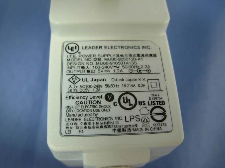
Click to zoom
Application Details
- Equipment Class
- DTS - Digital Transmission System
- Date of Grant
- Aug 08, 2011
- Application Purpose
- Original Equipment
- Date of Application
- Aug 08, 2011
- Equipment Note
- Wireless N Day/Night Home Network Camera
- Frequency Range
- 2422.00000000 - 2452.00000000
- Company
- D-Link Corporation
- Country
- United States
Documents & Files
Document Text
Text extracted from the exhibit documents filed with the FCC. Open a document above to read the original.
Users Manual
39D-Link DCS-942L User Manual Section 4 - Configuration Maintenance This section allows you to change the administrator’s password and configure the server settings for your camera. You can also manage the user account(s) that access to your camera. Admin Password Setting: To change your password, enter your current password and then enter the new one in the New Password and Confirm New Password fields. Add User Account: Create a new user for accessing the video image. Enter the user name, password, and password confirmation, and click Add. A maximum of 8 user accounts can be added into the user list. User List: Select a user from the drop-down menu and click Delete to remove the user account from having access to the camera images. RTSP Authentication: Enable user validation for RTSP streaming. HTTP Authentication: Enable user validation for HTTP streaming. Snapshot URL Authentication: Select Enable to allow access to the current camera snapshot via the web address indicated. Camera Name: Specify a name for your camera. OSD: In the Label field, you may enter a name to display on the image and check a box to put the current time on the image also. LED Light: Select Normal to enable the LED on the front of the device, or select off to disable the LED. It can also be set to flicker on and off. Admin 40D-Link DCS-942L User Manual Section 4 - Configuration System This section allows you to save and restore your configuration, restore the factory settings, and/or restart the camera. 41D-Link DCS-942L User Manual Section 4 - Configuration Firmware Upgrade Your current firmware version and date will be displayed on your screen. You may go to the D-Link Support Page to check for the latest firmware versions available. To upgrade the firmware on your DCS-942L, please download and save the latest firmware version from the D-Link Support Page to your local hard drive. Locate the file on your local hard drive by using the Browse button. Then, click the “Upload” button to start the firmware upgrade. 42D-Link DCS-942L User Manual Section 4 - Configuration Status Device Info This section displays detailed information about your device and network settings. 43D-Link DCS-942L User Manual Section 4 - Configuration Log The system log records camera events that have occurred. 44D-Link DCS-942L User Manual Section 5 - Security Wireless Security This section will show you the different levels of security you can use to protect your data from intruders. The DCS-942L offers the following types of security: • WPA-PSK (Pre-Shared Key) • WEP (Wired Equivalent Privacy) What is WEP? WEP stands for Wired Equivalent Privacy. It is based on the IEEE 802.11 standard and uses the RC4 encryption algorithm. WEP provides security by encrypting data over your wireless network so that it is protected as it is transmitted from one wireless device to another. To gain access to a WEP network, you must know the key. The key is a string of characters that you create. When using WEP, you must determine the level of encryption. The type of encryption determines the key length. 128-bit encryption requires a longer key than 64-bit encryption. Keys are defined by entering in a string in HEX (hexadecimal - using characters 0-9, A-F) or ASCII (American Standard Code for Information Interchange – alphanumeric characters) format. ASCII format is provided so you can enter a string that is easier to remember. The ASCII string is converted to HEX for use over the network. Four keys can be defined so that you can change keys easily. 45D-Link DCS-942L User Manual Section 5 - Security What is WPA? WPA, or Wi-Fi Protected Access, is a Wi-Fi standard that was designed to improve the security features of WEP (Wired Equivalent Privacy). The 2 major improvements over WEP: Improved data encryption through the Temporal Key Integrity Protocol (TKIP). TKIP scrambles the keys using a hashing algorithm and, by adding an integrity-checking feature, ensures that the keys haven’t been tampered with. WPA2 is based on 802.11i and uses Advanced Encryption Standard instead of TKIP. User authentication, which is generally missing in WEP, through the extensible authentication protocol (EAP). WEP regulates access to a wireless network based on a computer’s hardware-specific MAC address, which is relatively simple to be sniffed out and stolen. EAP is built on a more secure public-key encryption system to ensure that only authorized network users can access the network. WPA-PSK/WPA2-PSK uses a passphrase or key to authenticate your wireless connection. The key is an alpha-numeric password between 8 and 63 characters long. The password can include symbols (!?*&_) and spaces. This key must be the exact same key entered on your wireless router or access point. 46D-Link DCS-942L User Manual Section 5 - Security D-Link’s DCS-942L is a versatile and cost effective Network Camera offering both video and audio monitoring. It can also serve as a powerful surveillance system in security applications. The DCS-942L can be used with any wired or 802.11n/g wireless router. This section explains how to view the camera from either the Internet or from inside your internal network. Components Needed: • 1 DCS-942L Network Camera • 1 Ethernet Cable • A Wired or Wireless router such as the D-Link DIR-655 Wireless Router • Ethernet based PC for system configuration Setting up the DCS-942L for Use Behind a Router Installing a DCS-942L Network Camera on your network is an easy 4–step procedure: 1. Assign a local IP address to your network camera. 2. View the network camera using your Internet Explorer web browser. 3. Access the router with your web browser. 4. Open virtual server ports to enable remote image viewing. Note: These are manual steps; however, if you decide to use the wizard, it will perform every step automatically. This section is designed to walk you through the setup process for installing your camera behind a router and enable remote video viewing. For the basic setup of th…
Text truncated - open the document above for the full version.
Users Manual
38D-Link DCS-942L User Manual Section 4 - Configuration SD Card A list of files stored on the inserted SD card is displayed. By selecting the check box, you can selectively delete video or images. If you want to erase the SD card or if it is a new one, click Format SD Card. Note: Format SD Card will erase all the contents of the SD card. This page allows you to browse and manage the recorded files on an SD card which is inserted into the camera. 39D-Link DCS-942L User Manual Section 4 - Configuration Maintenance This section allows you to change the administrator’s password and configure the server settings for your camera. You can also manage the user account(s) that access to your camera. Admin Password Setting: To change your password, enter your current password and then enter the new one in the New Password and Confirm New Password fields. Add User Account: Create a new user for accessing the video image. Enter the user name, password, and password confirmation, and click Add. A maximum of 8 user accounts can be added into the user list. User List: Select a user from the drop-down menu and click Delete to remove the user account from having access to the camera images. RTSP Authentication: Enable user validation for RTSP streaming. HTTP Authentication: Enable user validation for HTTP streaming. Snapshot URL Authentication: Select Enable to allow access to the current camera snapshot via the web address indicated. Camera Name: Specify a name for your camera. OSD: In the Label field, you may enter a name to display on the image and check a box to put the current time on the image also. LED Light: Select Normal to enable the LED on the front of the device, or select off to disable the LED. It can also be set to flicker on and off. Admin 40D-Link DCS-942L User Manual Section 4 - Configuration System This section allows you to save and restore your configuration, restore the factory settings, and/or restart the camera. 41D-Link DCS-942L User Manual Section 4 - Configuration Firmware Upgrade Your current firmware version and date will be displayed on your screen. You may go to the D-Link Support Page to check for the latest firmware versions available. To upgrade the firmware on your DCS-942L, please download and save the latest firmware version from the D-Link Support Page to your local hard drive. Locate the file on your local hard drive by using the Browse button. Then, click the “Upload” button to start the firmware upgrade. 42D-Link DCS-942L User Manual Section 4 - Configuration Status Device Info This section displays detailed information about your device and network settings. 43D-Link DCS-942L User Manual Section 4 - Configuration Log The system log records camera events that have occurred. 44D-Link DCS-942L User Manual Section 5 - Security Wireless Security This section will show you the different levels of security you can use to protect your data from intruders. The DCS-942L offers the following types of security: • WPA-PSK (Pre-Shared Key) • WEP (Wired Equivalent Privacy) What is WEP? WEP stands for Wired Equivalent Privacy. It is based on the IEEE 802.11 standard and uses the RC4 encryption algorithm. WEP provides security by encrypting data over your wireless network so that it is protected as it is transmitted from one wireless device to another. To gain access to a WEP network, you must know the key. The key is a string of characters that you create. When using WEP, you must determine the level of encryption. The type of encryption determines the key length. 128-bit encryption requires a longer key than 64-bit encryption. Keys are defined by entering in a string in HEX (hexadecimal - using characters 0-9, A-F) or ASCII (American Standard Code for Information Interchange – alphanumeric characters) format. ASCII format is provided so you can enter a string that is easier to remember. The ASCII string is converted to HEX for use over the network. Four keys can be defined so that you can change keys easily. 45D-Link DCS-942L User Manual Section 5 - Security What is WPA? WPA, or Wi-Fi Protected Access, is a Wi-Fi standard that was designed to improve the security features of WEP (Wired Equivalent Privacy). The 2 major improvements over WEP: Improved data encryption through the Temporal Key Integrity Protocol (TKIP). TKIP scrambles the keys using a hashing algorithm and, by adding an integrity-checking feature, ensures that the keys haven’t been tampered with. WPA2 is based on 802.11i and uses Advanced Encryption Standard instead of TKIP. User authentication, which is generally missing in WEP, through the extensible authentication protocol (EAP). WEP regulates access to a wireless network based on a computer’s hardware-specific MAC address, which is relatively simple to be sniffed out and stolen. EAP is built on a more secure public-key encryption system to ensure that only authorized network users can access the network. WPA-PSK/WPA2-PSK uses a passphrase or key to authenticate your wireless connection. The key is an alpha-numeric password between 8 and 63 characters long. The password can include symbols (!?*&_) and spaces. This key must be the exact same key entered on your wireless router or access point. 46D-Link DCS-942L User Manual Section 5 - Security D-Link’s DCS-942L is a versatile and cost effective Network Camera offering both video and audio monitoring. It can also serve as a powerful surveillance system in security applications. The DCS-942L can be used with any wired or 802.11n/g wireless router. This section explains how to view the camera from either the Internet or from inside your internal network. Components Needed: • 1 DCS-942L Network Camera • 1 Ethernet Cable • A Wired or Wireless router such as the D-Link DIR-655 Wireless Router • Ethernet based PC for system configuration Setting up the DCS-942L for Use Behind a Router Installing a DCS-942L Network Camera on your network is an easy 4–step procedure: 1. Assign a local IP address to your network camera. 2.…
Text truncated - open the document above for the full version.
External Photos
Report No: 115289R-RFUSP42V01 Page: 187 of 201 Attachement EUT Photograph (1) EUT Photo (Power Adapter: AMIGO, AMS1-0501200FU) (2) EUT Photo Report No: 115289R-RFUSP42V01 Page: 188 of 201 (3) EUT Photo Report No: 115289R-RFUSP42V01 Page: 189 of 201 (4) EUT Photo (Power Adapter: LEADER, MU06-9050120-A1) (5) EUT Photo Report No: 115289R-RFUSP42V01 Page: 190 of 201 (6) EUT Photo
ID Label/Location Info
FCC ID.: KA2CS942LA1 FCC ID AND DoC Label The FCC ID and DoC Label will be placed on the equipment as shown in the photograph below. Wireless N Day/Night Home Network Camera Model No.: DCS-942L F F C C C C I I D D : : K K A A 2 2 C C S S 9 9 4 4 2 2 L L A A 1 1 This device complies with Part 15 of the FCC Rules. Operation is subject to the following two conditions: (1) this device may not cause harmful interference and (2) this device must accept any interference received, including interference that may cause undesired operation. S/N: Made in Taiwan Trade name: D-Link Model number.: DCS-942L
ID Label/Location Info
FCC ID.: KA2CS942LA1 FCC ID AND DoC Label The FCC ID and DoC Label will be placed on the equipment as shown in the photograph below. Wireless N Day/Night Home Network Camera Model No.: DCS-942L F F C C C C I I D D : : K K A A 2 2 C C S S 9 9 4 4 2 2 L L A A 1 1 This device complies with Part 15 of the FCC Rules. Operation is subject to the following two conditions: (1) this device may not cause harmful interference and (2) this device must accept any interference received, including interference that may cause undesired operation. S/N: Made in Taiwan Trade name: D-Link Model number.: DCS-942L
Internal Photos
Report No: 115289R-RFUSP42V01 Page: 191 of 201 (7) EUT Photo (8) EUT Photo Report No: 115289R-RFUSP42V01 Page: 192 of 201 (9) EUT Photo (10) EUT Photo Report No: 115289R-RFUSP42V01 Page: 193 of 201 (11) EUT Photo (12) EUT Photo Report No: 115289R-RFUSP42V01 Page: 194 of 201 (13) EUT Photo (14) EUT Photo Report No: 115289R-RFUSP42V01 Page: 195 of 201 (15) EUT Photo (16) EUT Photo Report No: 115289R-RFUSP42V01 Page: 196 of 201 (17) EUT Photo (18) EUT Photo Report No: 115289R-RFUSP42V01 Page: 197 of 201 (19) EUT Photo (20) EUT Photo Report No: 115289R-RFUSP42V01 Page: 198 of 201 (21) EUT Photo (22) EUT Photo Report No: 115289R-RFUSP42V01 Page: 199 of 201 (23) EUT Photo Report No: 115289R-RFUSP42V01 Page: 200 of 201 (24) EUT Photo Report No: 115289R-RFUSP42V01 Page: 201 of 201 (25) EUT Photo (ANT)
RF Exposure Info
Report No. 115289R-RF-US-Exp Page: 1 of 4 RF Exposure Evaluation declaration Product Name : Wireless N Day/Night Home Network Camera Model No. : DCS-942L FCC ID. : KA2CS942LA1 Applicant : D-Link Corporation Address : No.289, Sinhu 3rd Rd., Neihu District, Taipei City 114, Taiwan, R.O.C. Date of Receipt : 2011/05/13 Date of Declaration : 2011/07/15 Report No. : 115289R-RF-US-Exp Report Version : V1.0 The declaration results relate only to the samples calculated. The declaration shall not be reproduced except in full without the written approval of QuieTek Corporation. Report No. 115289R-RF-US-Exp Page: 2 of 4 1. RF Exposure Evaluation 1.1. Limits According to FCC 1.1310: The criteria listed in the following table shall be used to evaluate the environment impact of human exposure to radio frequency (RF) radiation as specified in 1.1307(b) LIMITS FOR MAXIMUM PERMISSIBLE EXPOSURE (MPE) Frequency Range (MHz) Electric Field Strength (V/m) Magnetic Field Strength (A/m) Power Density (mW/cm 2 ) Average Time (Minutes) (A) Limits for Occupational/ Control Exposures 300-1500 -- -- F/300 6 1500-100,000 -- -- 5 6 (B) Limits for General Population/ Uncontrolled Exposures 300-1500 -- -- F/1500 6 1500-100,000 -- -- 1 30 F= Frequency in MHz Friis Formula Friis transmission formula: Pd = (Pout*G)/(4*pi*r 2 ) Where Pd = power density in mW/cm 2 Pout = output power to antenna in mW G = gain of antenna in linear scale Pi = 3.1416 R = distance between observation point and center of the radiator in cm Pd id the limit of MPE, 1 mW/cm 2 . If we know the maximum gain of the antenna and the total power input to the antenna, through the calculation, we will know the distance r where the MPE limit is reached. 1.2. Test Procedure Software provided by client enabled the EUT to transmit and receive data at lowest, middle and highest channel individually. The temperature and related humidity: 18°Cand 78% RH. Report No. 115289R-RF-US-Exp Page: 3 of 4 1.3. Test Result of RF Exposure Evaluation Product Wireless N Day/Night Home Network Camera Test Mode Mode 1: Transmit Test Condition RF Exposure Evaluation Antenna Gain Antenna Gain: The maximum Gain measured in fully anechoic chamber is 1.3dBi or 1.35 in linear scale. Output Power into Antenna & RF Exposure Evaluation Distance: IEEE 802.11b WLAN Function Channel Channel Frequency (MHz) Output Power to Antenna (mW) Power Density at R = 20 cm (mW/cm 2 ) 1 2412 46.9894 0.01262 6 2437 43.9542 0.01180 11 2462 43.2514 0.01162 IEEE 802.11g WLAN Function Channel Channel Frequency (MHz) Output Power to Antenna (mW) Power Density at R = 20 cm (mW/cm 2 ) 1 2412 162.5549 0.04366 6 2437 159.2209 0.04276 11 2462 183.2314 0.04921 The power density Pd (4th column) at a distance of 20 cm calculated from the Friis transmission formula is far below the limit of 1 mW/cm 2 . Report No. 115289R-RF-US-Exp Page: 4 of 4 Product Wireless N Day/Night Home Network Camera Test Mode Mode 1: Transmit Test Condition RF Exposure Evaluation Antenna Gain Antenna Gain: The maximum Gain measured in fully anechoic chamber is 1.3dBi or 1.5 in linear scale. Output Power into Antenna & RF Exposure Evaluation Distance: IEEE 802.11n (20MHz) WLAN Function Channel Channel Frequency (MHz) Output Power to Antenna (mW) Power Density at R = 20 cm (mW/cm 2 ) 1 2412 181.5516 0.04876 6 2437 172.9816 0.04646 11 2462 157.7611 0.04237 IEEE 802.11n (40M) WLAN Function Channel Channel Frequency (MHz) Output Power to Antenna (mW) Power Density at R = 20 cm (mW/cm 2 ) 3 2422 205.5891 0.05522 6 2437 211.8361 0.05689 9 2452 212.3244 0.05702 The power density Pd (4th column) at a distance of 20 cm calculated from the Friis transmission formula is far below the limit of 1 mW/cm 2 .
Test Report
Report No: 115289R-RFUSP42V01 Page: 1 of 201 Test Report Product Name : Wireless N Day/Night Home Network Camera Model No. : DCS-942L FCC ID. : KA2CS942LA1 Applicant: D-Link Corporation Address : No.289, Sinhu 3rd Rd., Neihu District, Taipei City 114, Taiwan, R.O.C. Date of Receipt:2011/05/13 Issued Date :2011/07/15 Report No. :115289R-RFUSP42V01 Report Version :V1.0 The test results relate only to the samples tested. The test report shall not be reproduced except in full without the written approval of QuieTek Corporation. Report No: 115289R-RFUSP42V01 Page: 2 of 201 Test Report Certification Issued Date : 2011/07/15 Report No. : 115289R-RFUSP42V01 Product Name : Wireless N Day/Night Home Network Camera Applicant : D-Link Corporation Address : No.289, Sinhu 3rd Rd., Neihu District, Taipei City 114, Taiwan, R.O.C. Manufacturer : Alpha Networks Inc. M ODEL NO. : DCS-942L FCC ID. : KA2CS942LA1 EUT Voltage : AC 100-240V / 50/60Hz Trade Name : D-Link Applicable Standard : FCC CFR Title 47 Part 15 Subpart C Section 15.247:2010 ANSI C63.4: 2009 Test Result : Complied The test results relate only to the samples tested. The test report shall not be reproduced except in full without the written approval of QuieTek Corporation. Documented By : ( Carol Tsai / Engineering Adm. Specialist ) Reviewed By : ( JuBo Shen / Engineer ) Approved By : ( Roy Wang / Manager ) Report No: 115289R-RFUSP42V01 Page: 3 of 201 TABLE OF CONTENTS Description Page 1. GENERAL INFORMATION ............................................................................................................5 1.1. EUT D ESCRIPTION.................................................................................................................... 5 1.2. O PERATIONAL DESCRIPTION...................................................................................................... 9 1.3. T EST MODE............................................................................................................................. 10 1.4. T ESTED SYSTEM DETAILS........................................................................................................ 11 1.5. C ONFIGURATION OF TESTED SYSTEM....................................................................................... 11 1.6. EUT E XERCISE SOFTWARE..................................................................................................... 12 1.7. T EST FACILITY......................................................................................................................... 13 2. CONDUCTED EMISSION ............................................................................................................ 14 2.1. T EST EQUIPMENT.................................................................................................................... 14 2.2. T EST SETUP............................................................................................................................ 14 2.3. L IMITS..................................................................................................................................... 15 2.4. T EST PROCEDURE................................................................................................................... 15 2.5. T EST SPECIFICATION............................................................................................................... 15 2.6. U NCERTAINTY......................................................................................................................... 15 2.7. T EST RESULT.......................................................................................................................... 16 2.8. T EST PHOTO........................................................................................................................... 24 3. PEAK POWER OUTPUT ............................................................................................................. 26 3.1. T EST EQUIPMENT.................................................................................................................... 26 3.2. T EST SETUP............................................................................................................................ 26 3.3. T EST PROCEDURES................................................................................................................. 26 3.4. L IMITS..................................................................................................................................... 26 3.5. T EST SPECIFICATION............................................................................................................... 26 3.6. U NCERTAINTY......................................................................................................................... 26 3.7. T EST RESULT.......................................................................................................................... 27 4. RADIATED EMISSION ................................................................................................................. 31 4.1. T EST EQUIPMENT.................................................................................................................... 31 4.2. T EST SETUP............................................................................................................................ 31 4.3. L IMITS..................................................................................................................................... 32 4.4. T EST PROCEDURE................................................................................................................... 32 4.5. T EST SPECIFICATION............................................................................................................... 32 4.6. U NCERTAINTY......................................................................................................................... 32 4.7. T EST RESULT..............................................…
Text truncated - open the document above for the full version.
Test Report
Report No: 115289R-RFUSP42V01 Page: 101 of 201 5. RF antenna conducted test 5.1. Test Equipment The following test equipment is used during the test: RF antenna conducted test / SR7 Instrument ManufacturerModel No. Serial No Next Cal. Date Spectrum Analyzer R&S FSP 100561 2012/01/16 Note: 1. All equipments that need to calibrate are with calibration period of 1 year. 5.2. Test Setup RF Antenna Conducted Measurement: Report No: 115289R-RFUSP42V01 Page: 102 of 201 5.3. Limits In any 100 kHz bandwidth outside the frequency band in which the spread spectrum intentional radiator is operating, the radio frequency power that is produced by the intentional radiator shall be at least 20 dB below that in the 100 kHz bandwidth within the band that contains the highest level of the desired power, based on an RF conducted or radiated measurement. Attenuation below the general limits specified in Section 15.209(a) is not required. In addition, radiated emissions which fall in the restricted bands, as defined in Section 15.205(a), must also comply with the radiated emission limits specified in Section 15.209(a) (see Section 15.205(c)). 5.4. Test Procedure The EUT was setup according to ANSI C63.4: 2009 and tested according to DTS test procedure of Oct 2002 KDB558074 for compliance to FCC 47CFR 15.247 requirements Set RBW = 100 kHz, Set VBW> RBW, scan up through 10th harmonic. 5.5. Test Specification According to FCC Part 15 Subpart C Paragraph 15.247: 2010 5.6. Uncertainty Conducted is defined as ± 1.27dB Report No: 115289R-RFUSP42V01 Page: 103 of 201 5.7. Test Result Product Wireless N Day/Night Home Network Camera Test Item RF antenna conducted test Test Mode Transmit Date of Test 2011/06/03 Test Site SR7 IEEE 802.11b Channel No. Frequency (MHz) Measure Level (dBc) Limit (dBc) Result 1 2412 46.51 ≥20 Pass 11 2462 55.16 ≥20 Pass Channel 01 (2412MHz) Report No: 115289R-RFUSP42V01 Page: 104 of 201 Channel 11 (2462MHz) Report No: 115289R-RFUSP42V01 Page: 105 of 201 Product Wireless N Day/Night Home Network Camera Test Item RF antenna conducted test Test Mode Transmit Date of Test 2011/06/03 Test Site SR7 IEEE 802.11g Channel No. Frequency (MHz) Measure Level (dBc) Limit (dBc) Result 1 2412 33.95 ≥20 Pass 11 2462 44.24 ≥20 Pass Channel 01 (2412MHz) Report No: 115289R-RFUSP42V01 Page: 106 of 201 Channel 11 (2462MHz) Report No: 115289R-RFUSP42V01 Page: 107 of 201 Product Wireless N Day/Night Home Network Camera Test Item RF antenna conducted test Test Mode Transmit Date of Test 2011/06/03 Test Site SR7 IEEE 802.11n (20MHz) Channel No. Frequency (MHz) Measure Level (dBc) Limit (dBc) Result 1 2412 34.89 ≥20 Pass 11 2462 44.88 ≥20 Pass Channel 01 (2412MHz) Report No: 115289R-RFUSP42V01 Page: 108 of 201 Channel 11 (2462MHz) Report No: 115289R-RFUSP42V01 Page: 109 of 201 Product Wireless N Day/Night Home Network Camera Test Item RF antenna conducted test Test Mode Transmit Date of Test 2011/06/03 Test Site SR7 IEEE 802.11n (40MHz) Channel No. Frequency (MHz) Measure Level (dBc) Limit (dBc) Result 3 2422 29.70 ≥20 Pass 9 2452 31.50 ≥20 Pass Channel 03 (2422MHz) Report No: 115289R-RFUSP42V01 Page: 110 of 201 Channel 09 (2452MHz)
Test Report
Report No: 115289R-RFUSP42V01 Page: 127 of 201 6. Radiated Emission Band Edge 6.1. Test Equipment The following test equipments are used during the test: Band Edge / CB1 Instrument Manufacturer Model No. Serial No Next Cal. Date Double Ridged Guide Horn Antenna Schwarzback BBHA 9120D 743 2012/02/24 PSA Series Spectrum analyzer Agilent E4440A MY46187335 2012/01/06 Coaxial Cable Huber+Suhner AG Sucoflex 102 25623/2 2012/03/21 Note: 1. All equipments that need to calibrate are with calibration period of 1 year. 6.2. Test Setup RF Radiated Measurement: Report No: 115289R-RFUSP42V01 Page: 128 of 201 6.3. Limits Emissions radiated outside of the specified frequency bands, except for harmonics, shall be attenuated by at least 20dB below the level of the fundamental or to the general radiated emission limits in paragraph 15.209, whichever is the lesser attenuation. 6.4. Test Procedure The EUT was setup according to ANSI C63.4: 2009 and tested according to DTS test procedure of Oct 2002 KDB558074 for compliance to FCC 47CFR 15.247 requirements. The EUT and its simulators are placed on a turn table which is 0.8 meter above ground. The turn table can rotate 360 degrees to determine the position of the maximum emission level. The EUT was positioned such that the distance from antenna to the EUT was 3 meters. The antenna can move up and down between 1 meter and 4 meters to find out the maximum emission level. Both horizontal and vertical polarization of the antenna are set on measurement. In order to find the maximum emission, all of the interface cables must be manipulated according to ANSI C63.4: 2009 on radiated measurement. 6.5. Test Specification According to FCC Part 15 Subpart C Paragraph 15.247: 2010 6.6. Uncertainty The measurement uncertainty ± 3.9 dB above 1GHz Report No: 115289R-RFUSP42V01 Page: 129 of 201 6.7. Test Result Radiated is defined as Site : CB1 Time : 2011/06/06 - 13:31 Limit : FCC_SpartC_15.209_03M_PK Margin : 6 Probe : EFS_1-18G(2011-05) - HORIZONTAL Power : AC 120V/60Hz EUT : Wireless N Day/Night Home Network Camera Note : 802.11b 2412MHz Frequency (MHz) Correct Factor (dB) Reading Level (dBuV) Measure Level (dBuV/m) Margin (dB) Limit (dBuV/m) Detector Type 1 2310.000 29.125 26.96756.092-17.908 74.000 PEAK 2 * 2366.172 29.698 27.64857.345-16.655 74.000 PEAK 3 2390.000 29.940 26.49056.430-17.570 74.000 PEAK Note: 1. All readings above 1GHz are performed with peak and/or average measurements as necessary. 2. Peak measurements: RBW = 1MHz, VBW = 3 MHz, Sweep: Auto. 3. Average measurements: RBW = 1MHz, VBW = 10 Hz, Sweep: Auto. 4. “ * ”, means this data is the worst emission level. 5. Measurement Level = Reading Level + Correct Factor. 6. The average measurement was not performed when the peak measu…
Text truncated - open the document above for the full version.
Contact Information
Applicant
Brett Adair(General Counsel)
Test Firm
QuieTek CorporationWarren Lin
Technical Specifications
| # | Rule Parts | Frequency Range | Power Output |
|---|---|---|---|
| 2 | 15C | 2.42 GHz - 2.45 GHz | 212.00 mW |
Other Applications from D-Link Corporation

KA2CS6012A1
Jul 07, 20262K Fixed Indoor Cloud Camera, 2K Fixed Indoor Wi-Fi Camera
Equipment Class
DTS - Digital Transmission SystemKA2AE65UA1
Mar 02, 2026Wi-Fi 7 BE6500 USB 3.0 Dongle
Equipment Class
NII - Unlicensed National Information Infrastructure TXKA2APE9560A1
Nov 17, 2025BE9500 Celling mount Access Point
Equipment Class
6ID - 15E 6 GHz Low Power Indoor Access PointKA2AX9UA1
Dec 04, 2024AX900 Wi-Fi 6 USB Adapter, Wi-Fi 6 AX900 USB 2.0 Dongle
Equipment Class
DSS - Part 15 Spread Spectrum TransmitterKA2AC13UA1
Dec 04, 2024AC1300 Wi-Fi 5 USB Adapter, Wi-Fi 5 AC1300 USB 2.0 Dongle
Equipment Class
DTS - Digital Transmission System