KA2DBT1234A1Bluetooth USB Adapter
D-Link Corporation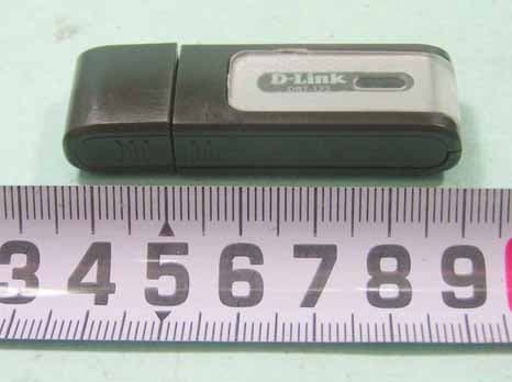
Click to zoom
Application Details
- Equipment Class
- DSS - Part 15 Spread Spectrum Transmitter
- Date of Grant
- Sep 29, 2005
- Application Purpose
- Original Equipment
- Date of Application
- Sep 29, 2005
- Equipment Note
- Bluetooth USB Adapter
- Frequency Range
- 2402.00000000 - 2480.00000000
- Company
- D-Link Corporation
- Country
- United States
Documents & Files
Document Text
Text extracted from the exhibit documents filed with the FCC. Open a document above to read the original.
Users Manual
1 USER GUIDE Rev.: 0.8 Date: 2005/09/27 Hereby, D-Link Corporation, declares that this device is in compliance with the essential requirements and other relevant provisions of the R&TTE Directive 1999/5/EC. This device will be sold in the following EEA countries: Austria, Italy, Belgium, Liechtenstein, Denmark, Luxembourg, Finland, Netherlands, France, Norway, Germany, Portugal, Greece, Spain, Iceland, Sweden, Ireland, United Kingdom. FEDERAL COMMUNICATIONS COMMISSION This device complies with Part 15 of the FCC Rules. Operation is subject to the following two conditions:(1) this device may not cause harmful interference, and (2) this device must accept any interference received, including interference that may cause undesired operation. NOTE This equipment has been tested and found to comply with the limits for a Class B digital device, pursuant to Part 15 of the FCC Rules. These limits are designed to provide reasonable protection against harmful interference in a residential installation. This equipment generates, uses and can radiated radio frequency energy and, if not installed and used in accordance with the instructions, may cause harmful interference to radio communications. However, there is no guarantee that interference will not occur in a particular installation If this equipment does cause harmful interference to radio or television reception, which can be determined by turning the equipment off and on, the user is encouraged to try to correct the interference by one or more of the following measures: -Reorient or relocate the receiving antenna. -Increase the separation between the equipment and receiver. -Connect the equipment into an outlet on a circuit different from that to which the receiver is connected. -Consult the dealer or an experienced radio/TV technician for help. Changes or modifications not expressly approved by the party responsible for compliance could void the user‘s authority to operate the equipment. This device and its antenna(s) must not be co-located or operating in conjunction with any other antenna or transmitter. FCC IDKA2DBT123A1 The Bluetooth word mark and logos are owned by the Bluetooth SIG, Inc.. Other trademarks and trade names are those of their respective owners. 2 . English 1.Bluetooth software installation and basic operations USB Adapter Installation 1. Windows Bluetooth Software Installation NOTE: Please install the USB Bluetooth software before inserting the USB adapter! • Place the installation CD-ROM into the PC, the setup should start automatically. If the setup does not start please go to Windows Explorer, locate the CD-ROM and run ‘autorun.exe’. • Choose ‘Install Drivers and Application Software’. • The InstallShield Wizard will start. 3 • On the Welcome screen click Next to continue. • Read the License Agreement and select ‘I accept the terms in the license agreement’. Click Next. 4 • Click Next to accept the default destination folder, click Change to browse to a new destination folder for the Bluetooth software. • Click Install to begin the installation of the bluetooth software. 5 • For Windows 2000/XP users, a "Driver Signature Notice" window appears, please click the "OK" button. • For Windows 98 users, a window appears which asks you to insert the Windows 98 CD-Rom. Insert the original Windows 98 CD Rom and click “OK”. • The "Bluetooth device not found" window appears. Insert the USB Bluetooth adapter in the USB port. Click "OK". 6 • Click Finish to complete the bluetooth software installation. • Click ‘Yes’ to restart the computer and complete the installation. • Click start/(settings)/controlpanel/system/devicemanager. Check under 'Universal Serial Bus controllers' that a 'USB Bluetooth Device' is installed. • If the information is not present please unplug the adapter, now plug in the adapter to initiate the driver. 7 Troubleshooting 1. Update the driver when the Bluetooth device can’t be recognized. 1.1 If the following screen appears, please follow the instruction below to update the driver for your Bluetooth device. 1.2 Go to “Control Panel” and find the unknown USB device, then double click “USB device” to update the driver. Double click “USB Device” 8 1.3 Select the item of “Don’t search I will choose the driver to install”, then click “Next” 1.4 Click the “Next” button. Select the item of “Don’t search I will choose the driver to install” Click “Update Driver” 9 10 1.5 Click “Finish” button 2. Switching from Microsoft Driver to WIDCOMM 2.1 Introduction The following describes how to switch from the Microsoft driver to the WIDCOMM driver on Windows XP so that the BTW Bluetooth software can be used with your Bluetooth USB device. This problem may arise when installing the WIDCOMM Bluetooth software on Windows XP SP1/SP2. When the device is first inserted the system attempts to locate a signed driver that will work with the device. In this case the Microsoft driver is installed first if its Bluetooth driver supports the device being installed. 2.2 Installing the Widcomm Bluetooth driver 2.2.1 CHECK TO SEE IF THE MICROSOFT DRIVER IS INSTALLED The Device Manager can be opened by right clicking on the “My Computer” icon and selecting the “Properties” menu option. When the Properties dialog appears select the “Hardware” tab and then click the “Device Manager” button. When Microsoft stack is in control then the Bluetooth Radios category is present in the Device Manager as shown below, Figure 1. There will be 2/3 devices under that category, depending on the implementation, these are: • Bluetooth Printing Support • Microsoft Bluetooth Enumerator • “Actual device”. (Example: NanoSira Bluetooth Reference Radio) 11 Figure1 2.2.2 INSTALLING THE WIDCOMM BLUETOOTH DRIVER From figure 1, highlight the “Actual Device”. Select “Action -> Properties” menu option. The following dialog will appear as shown below, Figure 2. Select Driver tab. Verify that the provider is Microsoft. Click the “Update Driver” button. Figure2 2.2.3 USING THE …
Text truncated - open the document above for the full version.
External Photos
SPORTON International Inc. PAGE NUMBER : A1 OF A7 TEL : 886-2-2696-2468 ISSUED DATE : Sep,29,2005 FAX : 886-2-2696-2255 APPENDIX A. Photographs of EUT SPORTON International Inc. PAGE NUMBER : A2 OF A7 TEL : 886-2-2696-2468 ISSUED DATE : Sep,29,2005 FAX : 886-2-2696-2255 SPORTON International Inc. PAGE NUMBER : A3 OF A7 TEL : 886-2-2696-2468 ISSUED DATE : Sep,29,2005 FAX : 886-2-2696-2255
Internal Photos
SPORTON International Inc. PAGE NUMBER : A4 OF A7 TEL : 886-2-2696-2468 ISSUED DATE : Sep,29,2005 FAX : 886-2-2696-2255 SPORTON International Inc. PAGE NUMBER : A5 OF A7 TEL : 886-2-2696-2468 ISSUED DATE : Sep,29,2005 FAX : 886-2-2696-2255 SPORTON International Inc. PAGE NUMBER : A6 OF A7 TEL : 886-2-2696-2468 ISSUED DATE : Sep,29,2005 FAX : 886-2-2696-2255 SPORTON International Inc. PAGE NUMBER : A7 OF A7 TEL : 886-2-2696-2468 ISSUED DATE : Sep,29,2005 FAX : 886-2-2696-2255
Test Report
FCC ID: KA2DBT1234A1 Issued on Sep. 27, 2005 Report No.: FR580104 SPORTON International Inc. TEL : 886-2-2696-2468 FAX : 886-2-2696-2255 FCC TEST REPORT CATEGORY : Portable PRODUCT NAME : Bluetooth USB Adapter FCC ID. : KA2DBT1234A1 FILING TYPE : Certification BRAND NAME : D-Link MODEL NAME : DBT-123 APPLICANT : D-Link Corporation 2F, No. 233-2, Pao-Chiao Road, Hsin-Tien, Taipei, Taiwan, R.O.C. MANUFACTURER : D-Link Corporation 2F, No. 233-2, Pao-Chiao Road, Hsin-Tien, Taipei, Taiwan, R.O.C. ISSUED BY : SPORTON INTERNATIONAL INC. 6F, No. 106, Sec. 1, Hsin Tai Wu Rd., Hsi Chih, Taipei Hsien, Taiwan, R.O.C. Statements: The test result in this report refers exclusively to the presented test model / sample. Without written approval of SPORTON International Inc., the test report shall not be reproduced except in full. Certificate or Test Report could not be used by the applicant to claim the product endorsement by CNLA, NVLAP or any agency of U.S. government. The test equipment used to perform the test is calibrated and traceable to NML/ROC or NIST/USA. Lab Code: 200079-0 FCC ID: KA2DBT1234A1 Issued on Sep. 27, 2005 Report No.: FR580104 SPORTON International Inc. Page No. : i TEL : 886-2-2696-2468 Issued Date : Sep. 27, 2005 FAX : 886-2-2696-2255: Table of Contents HISTORY OF THIS TEST REPORT .....................................................................................................................II CERTIFICATE OF COMPLIANCE.......................................................................................................................III 1. GENERAL DESCRIPTION OF EQUIPMENT UNDER TEST...........................................................................1 1.1. Applicant ......................................................................................................................................................................................... 1 1.2. Manufacturer ................................................................................................................................................................................... 1 1.3. Basic Description of Equipment under Test.................................................................................................................................... 1 1.4. Features of Equipment under Test ................................................................................................................................................. 1 1.5. Table for Carrier Frequencies ......................................................................................................................................................... 2 2. TEST CONFIGURATION OF THE EQUIPMENT UNDER TEST .....................................................................3 2.1. Connection Diagram of Test System .............................................................................................................................................. 3 2.2. The Test Mode Description............................................................................................................................................................. 5 2.3. Description of Test Supporting Units .............................................................................................................................................. 5 3. GENERAL INFORMATION OF TEST ..............................................................................................................6 3.1. Test Facility ..................................................................................................................................................................................... 6 3.2. Standards for Methods of Measurement......................................................................................................................................... 6 3.3. Frequency Range Investigated ....................................................................................................................................................... 6 3.4. Test Distance .................................................................................................................................................................................. 6 3.5. Test Software .................................................................................................................................................................................. 6 4. LIST OF MEASUREMENTS .............................................................................................................................7 4.1. Summary of the Test Results.......................................................................................................................................................... 7 5. TEST RESULT ..................................................................................................................................................8 5.1. Test of Hopping Channel Bandwidth .............................................................................................................................................. 8 5.2. Test of Hopping Channel Separation............................................................................................................................................ 11 5.3. Test of Number of Hopping Frequency......................................................................................................................................... 14 5.4. Test of Test of Dwell Time of Each Frequency ............................................................................................................................. 16 5.5. Maximum Peak Output Power ...................................................................................................................................................... 23 5.6. Test of Band Edges Emission...............................................................................................…
Text truncated - open the document above for the full version.
Test Setup Photos
FRONT VIEW REAR VIEW FRONT VIEW REAR VIEW
Contact Information
Applicant
Brett Adair(General Counsel)
Technical Contact
Sporton International IncWayne Hsu
[email protected]+886 3 327 3456
No. 52, Hwa Ya 1st Rd., Kwei-Shan · Tao Yuan · Taiwan
Test Firm
Sporton International Inc.Kathy Lin
Technical Specifications
| # | Rule Parts | Frequency Range | Power Output |
|---|---|---|---|
| 1 | 15C | 2.40 GHz - 2.48 GHz | 6.30 mW |
Other Applications from D-Link Corporation

KA2CS6012A1
Jul 07, 20262K Fixed Indoor Cloud Camera, 2K Fixed Indoor Wi-Fi Camera
Equipment Class
DTS - Digital Transmission SystemKA2AE65UA1
Mar 02, 2026Wi-Fi 7 BE6500 USB 3.0 Dongle
Equipment Class
NII - Unlicensed National Information Infrastructure TXKA2APE9560A1
Nov 17, 2025BE9500 Celling mount Access Point
Equipment Class
6ID - 15E 6 GHz Low Power Indoor Access PointKA2AX9UA1
Dec 04, 2024AX900 Wi-Fi 6 USB Adapter, Wi-Fi 6 AX900 USB 2.0 Dongle
Equipment Class
DSS - Part 15 Spread Spectrum TransmitterKA2AC13UA1
Dec 04, 2024AC1300 Wi-Fi 5 USB Adapter, Wi-Fi 5 AC1300 USB 2.0 Dongle
Equipment Class
DTS - Digital Transmission System