KA2DI-754Multimode 5GHz Wireless Router
D-Link Corporation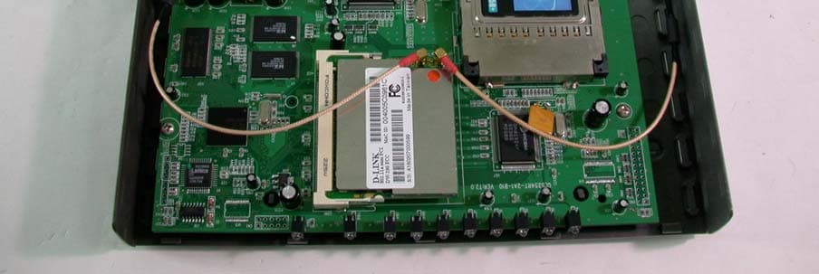
Click to zoom
Application Details
- Equipment Class
- NII - Unlicensed National Information Infrastructure TX
- Date of Grant
- Mar 03, 2003
- Application Purpose
- Original Equipment
- Date of Application
- Mar 03, 2003
- Equipment Note
- Multimode 5GHz Wireless Router
- Frequency Range
- 5260.00000000 - 5320.00000000
- Company
- D-Link Corporation
- Country
- United States
Documents & Files
Document Text
Text extracted from the exhibit documents filed with the FCC. Open a document above to read the original.
Users Manual
Wireless Router 5 GHz Multimode D-LINK AirPro DI-754 Manual Building Networks for People 2 Contents Package Contents................................................................................ 3 Introduction .......................................................................................... 4 Wireless Basics .................................................................................... 6 Getting Started ................................................................................... 10 Using the Configuration Menu ............................................................ 12 Networking Basics.............................................................................. 41 Troubleshooting .................................................................................. 70 Technical Specifications..................................................................... 76 Contacting Technical Support ............................................................. 79 Warranty and Registration.................................................................. 80 3 Contents of Package: D-Link AirPro DI-754 5GHz Multimode Wireless Broadband Router Power Adapter ñ 5V DC, 3A Manual and Warranty on CD Quick Installation Guide Ethernet Cable (CAT5 UTP/Straight Through) Computers with Windows, Macintosh, or Linux-based operating systems with an installed Ethernet adapter Package Contents Note: Using a power supply with a different voltage rating than the one included with the DI-754 will cause damage and void the warranty for this product. If any of the above items are missing, please contact your reseller. System Requirements: ! ! ! ! ! ! ! Ethernet-Based Cable or DSL Modem ! Internet Explorer Version 5.5 or Netscape Navigator Version 4.79 and Above 4 Introduction D-Link introduces the 802.11a wireless broadband router with optional 802.11b connection (using the D-Link AirPlus DWL-650+ Cardbus Adapter), as part of the D-Link AirPro series of wireless networking products. The new D-Link AirPro DI-754 Multimode Wireless Router serves both 802.11a wireless networks at 54 Mbps (72 Mbps in Turbo mode * ) and 802.11b wireless networks (when used with the installed D-Link AirPlus DWL-650+ Cardbus Adapter) at 11Mbps (22 Mbps with D-Link AirPlus products.) The DI-754 will automatically obtain an IP address and forward additional IP addresses to multiple clients for a seamless network connection and shared Internet access. At 54Mbps (up to 72Mbps in Turbo mode * ) in the 5GHz frequency range and a simultaneous 11 Mbps (up to 22 Mbps with D-Link AirPlus products when the optional Cardbus Adapter is installed) in the 2.4GHz frequency range, the D- Link AirPro DI-754 multimode router is capable of delivering the fastest standards-based wireless data transfers. Based on IEEE 802.11a and 802.11b technology, this next-generation multimode wireless access point provides excellent network interoperability. Armed with powerful management and security capabilities, the D-Link Air Pro DI-754 has an intuitive and secure web-based interface that is powered by an embedded web server. After completing the steps outlined in the Quick Installation Guide (included in your package) not only will you have the ability to share information and resources, but you will also be able to enjoy the freedom that wireless networking delivers, at speeds capable of handling a video stream. *When used with other D-Link AirPro products. 5 Expansion Slot for optional DWL-650+ Cardbus Adapter* Supports up to 152-bit WEP with dynamic keying Advanced firewall and security Supports multi-sessions with VPN passthrough Fully compatible with 802.11b standard Supports data transfer rates of up to 22 mbps at 2.4GHz Supports up to 256-bit WEP Encryption ! ! ! *The Expan- sion Slot on the DI-754 will only work with a D-Link DWL-650+. Make sure the DI-754 Router is completely powered off before inserting the DWL-650+ into the Expansion Slot. Advanced Security Features Features ! ! ! ! ! ! Features with Optional DWL-650+ (D-Link DWL-650+ is available as a separate purchase) ! ! ! 1.Environmental factors may adversely affect range Pressing the Reset Button restores the router to its original factory default settings. Receptor for the Power Adapter The WAN port is the connection for the Ethernet cable to the Cable or DSL modem LAN ports automatically sense cable type when connecting to Ethernet- enabled computers. With its web-based interface for easy integration into an existing network (accessible from most Internet browser applications), the DI-754 works with popular operating systems including Macintosh, Linux and Windows. This Manual is designed to help you connect the DI-754 into an existing 802.11a or 802.11b wireless network. Please take a look at the Getting Started section in this manual to see an example of an Infrastructure network using the DI-754. Connections Setup Wizard for quick installation Fully compatible with 802.11a standard Supports data transfer rates of up to 54 Mbps at 5GHz Ethernet cable included Wireless range of up to 328 feet (100 meters) indoors 1 3 year limited warranty (USA only) 6 LEDS LED stands for Light-Emitting Diode. The DI-754 has the following LEDs as shown below: D-Link wireless products are based on industry standards to provide easy- to-use and compatible high-speed wireless connectivity within your home, business or public access wireless networks. Strictly adhering to the IEEE standard, the D-Link wireless family of products will allow you to securely access the data you want, when and where you want it. You will be able to enjoy the freedom that wireless networking delivers. A wireless local area network (WLAN) is a cellular computer network that transmits and receives data with radio signals instead of wires. Wireless LANs are used increasingly in both home and office environments, and public areas such as airports, coffee shops and universities. Innovative ways Wireless Basics LED LED Activit…
Text truncated - open the document above for the full version.
Users Manual
62 Networking Basics Sharing a network printer Click on Add a printer Click Next Select Network Printer Click Next ! ! ! ! 63 Networking Basics Sharing a network printer Select Browse for a printer Click Next Select the printer you would like to share Click Next Click Finish ! ! ! ! 64 Networking Basics Sharing a network printer To check for proper installation: Go to Start > Printers and Faxes The printer icon will appear at right, indicating proper installation. You have completed adding the printer. To share this printer on your network: Remember the printer name Run the Add Printer Wizard on all the computers on your network Make sure you have already run the Network Setup Wizard on all the network computers After you run the Add Printer Wizard on all the computers in the network, you can share the printer. ! ! ! ! ! 65 Networking Basics Sharing an LPR printer To share an LPR printer (using a print server,) you will need a Print Server such as the DP-101P+. Please make sure that you have run the Network Setup Wizard on all the computers on your network. To share an LPR printer, please follow these directions: Go to Start > Printers and Faxes Click on Add a Printer The screen to the right will appear Click Next Select Local Printer... Click Next ! ! ! ! ! 66 Networking Basics Sharing an LPR printer Select Create a new port From the pull-down menu, select Standard TCP/IP Port, as shown. Click Next Please read the instructions on this screen Click Next Enter the Printer IP Address and the Port Name, as shown. Click Next ! ! ! ! ! ! ! 67 Networking Basics Sharing an LPR printer In this screen, select Custom Click Settings Enter the Port Name and the Printer Name or IP Address. Select LPR Enter a Queue Name (if your Print- Server/ Gateway has more than one port, you will need a Queue name.) Click OK ! ! ! ! ! ! 68 Networking Basics Sharing an LPR printer Click Next Select Keep existing driver If the printer driver is already installed, do the following: Click Have Disk Insert the printer driver disk that came with your printer. Select the printer you are adding from the list of Printers. Click Finish This screen will show you information about your printer. ! ! ! ! ! ! ! 69 Networking Basics Sharing an LPR printer Note: You must run the Network Setup Wizard on all the computers on your network before you run the Add Printer Wizard. Please run the Add Printer Wizard on all the computers on your network in order to share the printer. Click Finish to complete the addition of the printer. This screen will display informa- tion about your printer. Click Next Select Yes, to print a test page. Click Next Please remember the name of your printer. You will need this information when you use the Add Printer Wizard on the other computers on your network. You can rename your printer if you choose. It is optional. ! ! ! ! ! ! ! 70 1.The computer used to configure the DI-754 cannot access the Configuration menu. Check that the Ethernet LED on the DI-754 is ON. If the LED is not ON, check that the cable for the Ethernet connection is securely inserted. Check that the Ethernet Adapter is working properly. Please see item 3 (Check that the drivers for the network adapters are installed properly) in this Troubleshooting section to check that the drivers are loaded properly. Check that the IP Address is in the same range and subnet as the DI-754. Please see Checking the IP Address in Windows XP in the Networking Basics section of this manual. Note: The IP Address of the DI-754 is 192.168.0.1. All the computers on the network must have a unique IP Address in the same range, e.g., 192.168.0.x. Any computers that have identical IP Addresses will not be visible on the network. They must all have the same subnet mask, e.g., 255.255.255.0 Do a Ping test to make sure that the DI-754 is responding. Go to Start>Run>Type Command>Type ping 192.168.0.1. A successful ping will show four replies. Troubleshooting This Chapter provides solutions to problems that can occur during the installation and operation of the DI-754 Wireless Broadband Router. We cover various aspects of the network setup, including the network adapters. Please read the following if you are having problems. Note: If you have changed the default IP Address, make sure to ping the correct IP Ad- dress assigned to the DI-754. Note: It is recommended that you use an Ethernet connection to configure the DI-754 Wireless Broadband Router. ! ! ! ! 71 2. The wireless client cannot access the Internet in the Infrastructure mode. Make sure the wireless client is associated and joined with the correct Access Point. To check this connection: Right-click on the Local Area Connection icon in the taskbar> select View Available Wireless Networks. The Connect to Wireless Network screen will appear. Please make sure you have selected the correct available network, as shown in the illustrations below. Troubleshooting Check that the IP Address assigned to the wireless adapter is within the same IP Address range as the access point and gateway. (Since the DI-754 has an IP Address of 192.168.0.1, wireless adapters must have an IP Address in the same range, e.g., 192.168.0.x. Each device must have a unique IP Address; no two devices may have the same IP Address. The subnet mask must be the same for all the computers on the network.) To check the IP Address assigned to the wireless adapter, double-click on the Local Area Connection icon in the taskbar > select the Support tab and the IP Address will be displayed. (Please refer to Checking the IP Address in the Networking Basics section of this manual.) If it is necessary to assign a Static IP Address to the wireless adapter, please refer to the appropriate section in Networking Basics. If you are entering a DNS Server address you must also enter the Default Gateway Address. (Remember that if you have a DHCP-capable router, you will not need to assign a Static IP Address. See Networking Basics: Assigning a Static IP Address.) …
Text truncated - open the document above for the full version.
Users Manual
82 Governing Law: This Limited Warranty shall be governed by the laws of the State of California. Some states do not allow exclusion or limitation of incidental or consequential damages, or limitations on how long an implied warranty lasts, so the foregoing limitations and exclusions may not apply. This limited warranty provides specific legal rights and the product owner may also have other rights which vary from state to state. Trademarks: D-Link is a registered trademark of D-Link Systems, Inc. Other trademarks or registered trademarks are the property of their respective manufacturers or owners. Copyright Statement: No part of this publication or documentation accompanying this Product may be reproduced in any form or by any means or used to make any derivative such as translation, transformation, or adaptation without permission from D-Link Corporation/D-Link Systems, Inc., as stipulated by the United States Copyright Act of 1976. Contents are subject to change without prior notice. Copyright © 2002 by D-Link Corporation/D-Link Systems, Inc. All rights reserved. CE Mark Warning: This is a Class B product. In a domestic environment, this product may cause radio interference, in which case the user may be required to take adequate measures. FCC Statement: This equipment has been tested and found to comply with the limits for a Class B digital device, pursuant to part 15 of the FCC Rules. These limits are designed to provide reasonable protection against harmful interference in a residential installation. This equipment generates, uses, and can radiate radio frequency energy and, if not installed and used in accordance with the instructions, may cause harmful interference to radio communication. However, there is no guarantee that interference will not occur in a particular installation. If this equipment does cause harmful interference to radio or television reception, which can be determined by turning the equipment off and on, the user is encouraged to try to correct the interference by one or more of the following measures: Reorient or relocate the receiving antenna. Increase the separation between the equipment and receiver. Connect the equipment into an outlet on a circuit different from that to which the receiver is connected. Consult the dealer or an experienced radio/TV technician for help. Register online your D-Link product at http://support.dlink.com/register/ ! ! ! FCC Caution: Any changes or modifications not expressly approved by the party responsible for compliance could void the userís authority to operate this equipment. (1) The devices are restricted to indoor operations within the 5.15 to 5.25GHz range. (2) For this device to operate in the 5.15 to 5.25GHz range, the devices must use integral antennas. This device complies with Part 15 of the FCC Rules. Operation is subject to the following two conditions: (1) This device may not cause harmful interference, and (2) this device must accept any interference received, including interference that may cause undesired operation. IMPORTANT NOTE: FCC Radiation Exposure Statement: This equipment complies with FCC radiation exposure limits set forth for an uncontrolled environment. The antenna(s) used for this equipment must be installed to provide a separation distance of at least eight inches (20 cm) from all persons. The Airpro DI-754 system must not be operated in conjunction with any other transmitter or antenna. 02/10/03 ! The Manufacturer is not responsible for any radio or TV interference caused by unauthorized modifications to this equipment; such modifications could void the userís authority to operate the equipment.
Cover Letter(s)
D-Link Corporation No.8, Li-shing Rd VII,Science-based Industrial park, Hsinchu,Taiwan,R.O.C. TEL.:+886+3-563-6666 FAX:+886+3-563-6789 FCC ID: KA2DI-754 Federal Communications Commission Authorization and Evaluation Division Confidentiality Request Pursuant to Sections 0.457 and 0.459 of the Commission¡¦ s Rul es, t he Appli cant hereby requests confidential treatment of information accompanying this Application as outlined below: Schematics Block Diagram The above materials contain trade secrets and proprietary information not customarily released to the public. The public disclosure of these matters might be harmful to the Applicant and provide unjustified benefits to its competitors. The Applicant understands that pursuant to Rule 0.457, disclosure of this Application and all accompanying documentation will not be made before the date of the Grant for this application. Sincerely ------------------------------------------- Leeming Li / Associate Project Manager D-LINK Corporation Tel: +886 3 563-6666ext.6613 Fax: +886 3 578-1861 e-mail: [email protected]
Cover Letter(s)
American Telecommunications Certification Body Inc. 6731 Whittier Ave, McLean, VA 22101 January 30, 2003 RE: FCC ID: KA2 DI-754 Attention: Ellis Wu I have a few comments on this Application. 1. Please note that the Block Diagram is not in accordance with 2.1033 which states, “A block diagram showing the frequency of all oscillators in the device. The signal path and frequency shall be indicated at each block..” Please provide a Block diagram in accordance with 2.1033 xxx 2. From the photos the device appears to have a 2.4 GHz PCMCIA WLAN transmitter as well at the EUT. This would put the two transmitters collocated to each other. Depending upon the power of the two transmitters this may be a problem. For example, the MPE for this device says both transmitters are about 80mW each. The operational description of the device is not sufficient to make any kind of determination on this issue. Thus collocation issues cannot be determined until a full disclosure of the operating conditions likely with the PCMCIA 2.4 GHZ WLAN and 5 GHz UNII in conjunction with each other is provided. Please provide a concise technical description of how these two transmitters work with each other. (i.e. can they transmit at the same time? What have you done to show what happens when these two devices are operating in conjunction with each other? How does the proximity of the transmitters affect the MPE of the other transmitter? Etc) xxx 3. Please note that the manual states the device cannot be collocated with another transmitter, yet this is exactly what you are doing when you operate the 5GHz UNII and the 2.4GHz WLAN. Please resolve this conflict in your manual. xxx 4. The 2.3GHz WLAN is not listed in the support equipment. It is important that this collocated transmitter be shown in the filing. Please provide accurate FCC ID information for this PCMCIA WLAN. xxx Dennis Ward mailto:[email protected] The items indicated above must be submitted before processing can continue on the above referenced application. Failure to provide the requested information may result in application termination. Correspondence should be considered part of the permanent submission and may be viewed from the Internet after a Grant of Equipment Authorization is issued. Please do not respond to this correspondence using the email reply button. In order for your response to be processed expeditiously, you must submit your documents through the AmericanTCB.com website. Also, please note that partial responses increase processing time and should not be submitted. Any questions about the content of this correspondence should be directed to the sender.
Cover Letter(s)
1 dward From: [email protected] Sent: Sunday, March 02, 2003 6:38 PM To: [email protected] Cc: 'Alan Lane ADT'; [email protected] Subject: ¦^«H¡G KA2DI-754 COMMENTS Dear Dennis, (1)650 WLAN is accomplished via software, only the 650WLAN card inserted into the expansion slot can be activated (2)Yes, both EUT and the WLAN expansion card were operating during Radiated Spurious emissions Thanks 吳佳鑫 / Ellis Wu E-mail : [email protected] 誠信科技 / ADT Corp. TEL : +886 3 3270910 #24 FAX : +886 3 3270892 "dward" <[email protected] 收件人: <[email protected]> m> 副本抄送: "'Alan Lane ADT'" <[email protected]>, <[email protected]>, 2003/03/03 <[email protected]> 09:58 AM 主旨: KA2DI-754 COMMENTS 請回信 給 dward HI Ellis Thanks, I guess I did not make my request clear. I understand that the manual says the expansion slot only works with the 650 WLAN. But is this accomplished via software (i.e. it looks at the PCMCIA card plug and play firmware and only activates the EUT operability for the expansion slot if the 650 and only the 650 card is inserted) or is it done via hardware (i.e. only cards purchased from D-link for this specific application and having a hardware selection capability built into the card and the EUT activate the expansion slot in the EUT. Also, what about the verification that both EUT and the WLAN expansion card wer operating during Radiated Spurious emissions? Thanks Dennis -----Original Message----- From: [email protected] [mailto:[email protected]] Sent: Sunday, March 02, 2003 5:27 PM 2 To: [email protected] Cc: Alan Lane ADT; [email protected]; [email protected] Subject: 回信: Re: [Fwd: KA2DI-754 COMMENTS] Dear Dennis, Please see page 5 on the user manual. Thanks and Best Regards. 吳佳鑫 / Ellis Wu E-mail : [email protected] 誠信科技 / ADT Corp. TEL : +886 3 3270910 #24 FAX : +886 3 3270892 Dennis Ward <dennis@yosemi 收件人: [email protected] te.net> 副本抄送: [email protected], Alan Lane ADT <[email protected]> 2003/03/02 主旨: Re: [Fwd: KA2DI-754 COMMENTS] 11:09 AM 請回信 給 dward Hi Ellis I am about ready to issue the grant on this item, but I do not see in the manual where the PCMCIA is a dedicated slot for use only with the 650 card. Also, Please verify that the 650 was operational during spurious emissions testing. ONce these are confirmed, I can issue the grant. thanks Dennis Dennis Ward wrote: 3 > I have not heard anything on this issue from you. I have attached the > original request for in formation. thanks > Dennis > > ------------------------------------------------------------------------ > > Subject: KA2DI-754 COMMENTS > Date: Thu, 30 Jan 2003 21:30:04 -0800 > From: Dennis Ward <[email protected]> > Reply-To: [email protected] > To: Ellis - ADT <[email protected]> > References: <[email protected]> > > Hi Ellis > attached are the comments on this application. > Thanks > Dennis > > ------------------------------------------------------------------------ > Name: 1-30-03 KA2DI-754 ATCB Comments.pdf > 1-30-03 KA2DI-754 ATCB Comments.pdf Type: Acrobat (application/pdf) > Encoding: base64
Cover Letter(s)
41 Using the Network Setup Wizard in Windows XP In this section you will learn how to establish a network at home or work, using Microsoft Windows XP. Note: Please refer to websites such as http://www.homenethelp.com and http://www.microsoft.com/windows2000 for information about networking computers using Windows 2000, ME or 98. Go to Start>Control Panel>Network Connections Select Set up a home or small office network Networking Basics When this screen appears, Click Next. 42 Please follow all the instructions in this window: Networking Basics Click Next In the following window, select the best description of your computer. If your computer connects to the internet through a gateway/router, select the second option as shown. Click Next 43 Enter a Computer description and a Computer name (optional.) Networking Basics Click Next Enter a Workgroup name. All computers on your network should have the same Workgroup name. Click Next 44 Please wait while the Network Setup Wizard applies the changes. Networking Basics When the changes are complete, click Next. Please wait while the Network Setup Wizard configures the computer. This may take a few minutes. 45 Networking Basics In the window below, select the option that fits your needs. In this example, Create a Network Setup Disk has been selected. You will run this disk on each of the computers on your network. Click Next. Insert a disk into the Floppy Disk Drive, in this case drive A. 46 Networking Basics Please read the information under Hereís how in the screen below. After you com- plete the Network Setup Wizard you will use the Network Setup Disk to run the Network Setup Wizard once on each of the computers on your network. To continue click Next. 47 Networking Basics Please read the information on this screen, then click Finish to complete the Network Setup Wizard. The new settings will take effect when you restart the computer. Click Yes to restart the computer. You have completed configuring this computer. Next, you will need to run the Network Setup Disk on all the other computers on your network. After run- ning the Network Setup Disk on all your computers, your new wireless net- work will be ready to use. 48 ! Networking Basics Naming your Computer To name your computer, please follow these directions:In Windows XP: Click Start (in the lower left corner of the screen) Right-click on My Computer Select Properties and click ! ! ! ! ! Select the Computer Name Tab in the System Properties window. You may enter a Com- puter Description if you wish; this field is optional. To rename the computer and join a domain, Click Change. 49 Networking Basics Naming your Computer ! In this window, enter the Computer name Select Workgroup and enter the name of the Workgroup All computers on your network must have the same Workgroup name. Click OK ! ! ! Checking the IP Address in Windows XP The wireless adapter-equipped computers in your network must be in the same IP Address range (see Getting Started in this manual for a definition of IP Address Range.) To check on the IP Address of the adapter, please do the following: Right-click on the Local Area Connection icon in the task bar Click on Status ! ! 50 Networking Basics Checking the IP Address in Windows XP This window will appear. Click the Support tab Click Close ! ! Assigning a Static IP Address in Windows XP/2000 Note: Residential Gateways/Broadband Routers will automatically assign IP Ad- dresses to the computers on the network, using DHCP (Dynamic Host Configura- tion Protocol) technology. If you are using a DHCP-capable Gateway/Router you will not need to assign Static IP Addresses. If you are not using a DHCP capable Gateway/Router, or you need to assign a Static IP Address, please follow these instructions: ! ! Go to Start Double-click on Control Panel 51 Networking Basics Assigning a Static IP Address in Windows XP/2000 ! Double-click on Network Connections ! ! Double-click on Properties Right-click on Local Area Connections 52 Networking Basics Assigning a Static IP Address in Windows XP/2000 Input your IP address and subnet mask. (The IP Addresses on your network must be within the same range. For example, if one computer has an IP Address of 192.168.0.2, the other computers should have IP Addresses that are sequential, like 192.168.0.3 and 192.168.0.4. The subnet mask must be the same for all the computers on the network.) Input your DNS server addresses. (Note: If you are entering a DNS server, you must enter the IP Address of the Default Gateway.) ! Click on Internet Protocol (TCP/IP) Click Properties ! ! ! ! Click OK The DNS server address will be supplied by your ISP (Internet Service Provider). If the DNS Server address is not available from your ISP, you may input 192.168.0.1 in this field. 53 Networking Basics Assigning a Static IP Address with Macintosh OSX ! ! ! ! Go to the Apple Menu and se- lect System Preferences cClick on Network Select Built-in Ethernet in the Show pull-down menu Select Manually in the Configure pull-down menu Input the Domain Name Server address. Your ISP (Internet Service Provider) will provide the IP address of the DNS Server. If the DNS Server address is not avail- able from your ISP, you may input 192.168.0.1 in this field. ! ! Input the Static IP Address, the Subnet Mask and the Router IP Address in the appropriate fields ! Click Apply Now 54 Networking Basics Selecting a Dynamic IP Address with Macintosh OSX Go to the Apple Menu and select System Preferences Click on Network Select Built-in Ethernet in the Show pull-down menu Select Using DHCP in the Configure pull-down menu Click Apply Now ! ! ! ! ! The IP Address, Subnet mask, and the Routerís IP Address will appear in a few seconds ! 55 Networking Basics Checking the Wireless Connection by Pinging in Windows XP and 2000 Checking the Wireless Connection by Pinging in Windows Me and 98 Go to Start > Run > type cmd. A window similar to this one will appear. Type ping xxx.xxx.xxx.xxx, where xxx is th…
Text truncated - open the document above for the full version.
External Photos
Page 1 ANNEX PHOTOGRAPHS OF EUT Page 2 Page 3
ID Label/Location Info
754 FCC ID:KA2DI-754
ID Label/Location Info
754 FCC ID:KA2DI-754
Internal Photos
Page 3 Page 4 Page 5 Page 6 Page 7 Page 8 Page 9 Page 10 Page 11 Page 12 Page 13
Operational Description
FCC ID: KA2DI-754 ADT No.910909R01 Technical Description This device is a Multimode 5GHz Wireless Router, the maximum data rate could be up to 54Mbps. It operated in the 5.15 to 5.35 GHz frequency band. This device also provides expansion slot to exclusively operate with a D-Link AirPlus DWL-650+ cardbus adapter(FCC ID:O7J-GL242201), this 2.4GHz cardbus adapter can be operated simultaneously with the internal 5 GHz transmitter, and the total MPE of these combination is shorter than 20 cm. The transmitter of the EUT is powered by host equipment. The antenna used in this product is Dipole without antenna connector. Under normal use condition, the user has to keep at least 20cm separation distance between radiator and the body of the user. For more detailed instruction, please take a look at the user’s manual. FCC 15.407(c) states : The device shall automatically discontinue transmission in case of either absence of information to transmit or operational failure. These provisions are not intended to preclude the transmission of control or signaling information or the use of repetitive codes used by certain digital technologies to complete frame or burst intervals. Applicants shall include in their application for equipment authorization a description of hoe this requirement is met” Data transmission is always initiated by software, which is then pass down through the MAC, through the digital and analog baseba…
Text truncated - open the document above for the full version.
Contact Information
Applicant
Brett Adair(General Counsel)
Technical Contact
Advance Data Technology CorporationEllis Wu
[email protected]886-3-5636789
13-1, Lane19, WenShan 3rd ., St., · Taoyuan · Taiwan
Test Firm
Bureau Veritas CPS (H.K.) Ltd. Taoyuan BranchTommy Wu
Technical Specifications
| # | Rule Parts | Frequency Range | Power Output |
|---|---|---|---|
| 2 | 15E | 5.26 GHz - 5.32 GHz | 78.00 mW |
Other Applications from D-Link Corporation
KA2CS6530A1
Sep 08, 20262K Pan & Tilt Outdoor Wi-Fi Camera
Equipment Class
DTS - Digital Transmission System
KA2CS6012A1
Jul 07, 20262K Fixed Indoor Cloud Camera, 2K Fixed Indoor Wi-Fi Camera
Equipment Class
DTS - Digital Transmission SystemKA2AE65UA1
Mar 02, 2026Wi-Fi 7 BE6500 USB 3.0 Dongle
Equipment Class
NII - Unlicensed National Information Infrastructure TXKA2APE9560A1
Nov 17, 2025BE9500 Celling mount Access Point
Equipment Class
6ID - 15E 6 GHz Low Power Indoor Access PointKA2AX9UA1
Dec 04, 2024AX900 Wi-Fi 6 USB Adapter, Wi-Fi 6 AX900 USB 2.0 Dongle
Equipment Class
DSS - Part 15 Spread Spectrum Transmitter