KA2DI524A2Wireless G Router
D-Link Corporation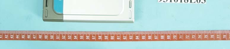
Click to zoom
Application Details
- Equipment Class
- DTS - Digital Transmission System
- Date of Grant
- Jan 11, 2005
- Application Purpose
- Original Equipment
- Date of Application
- Jan 11, 2005
- Equipment Note
- Wireless G Router
- Frequency Range
- 2412.00000000 - 2462.00000000
- Company
- D-Link Corporation
- Country
- United States
Documents & Files
Document Text
Text extracted from the exhibit documents filed with the FCC. Open a document above to read the original.
Users Manual
802.11g/2.4GHz Manual Building Networks for People Wireless Router D-Link AirPlus G DI-524DI-524 DI-524DI-524 DI-524 TM 2 Contents Package Contents................................................................................ 3 Introduction............................................................................................ 4 Wireless Basics .................................................................................... 8 Getting Started.................................................................................... 11 Using the Configuration Menu.............................................................. 12 Networking Basics.............................................................................. 39 Troubleshooting................................................................................... 54 Technical Specifications...................................................................... 61 Frequently Asked Questions................................................................ 64 Contacting Technical Support.............................................................. 92 Warranty and Registration................................................................... 93 3 Internet Explorer Version 6.0 or Netscape Navigator Version 6.0 and Above Contents of Package: D-Link AirPlus G DI-524 802.11g/2.4GHz Wireless Router Power Adapter-DC 5V, 2.5A Manual and Warranty on CD Quick Installation Guide Ethernet Cable (All the DI-524’s Ethernet ports are Auto-MDIX) Computers with Windows, Macintosh, or Linux-based operating systems with an installed Ethernet adapter Package Contents Note: Using a power supply with a different voltage rating than the one included with the DI-524 will cause damage and void the warranty for this product. If any of the above items are missing, please contact your reseller. System Requirements for Configuration: Ethernet-Based Cable or DSL Modem 4 Introduction The D-Link AirPlus G DI-524 802.11g/2.4 Ghz Wireless Router is an 802.11g high- performance, wireless router that supports high-speed wireless networking at home, at work or in public places. Unlike most routers, the DI-524 provides data transfers at up to 54 Mbps (compared to the standard 11 Mbps) when used with other D-Link AirPlus G products. The 802.11g standard is backwards compatible with 802.11b products. This means that you do not need to change your entire network to maintain connectivity. You may sacrifice some of 802.11g’s speed when you mix 802.11b and 802.11g devices, but you will not lose the ability to communicate when you incorporate the 802.11g standard into your 802.11b network. You may choose to slowly change your network by gradually replacing the 802.11b devices with 802.11g devices . In addition to offering faster data transfer speeds when used with other 802.11g products, the DI-524 has the newest, strongest, most advanced security features available today. When used with other 802.11g WPA (WiFi Protected Access) and 802.1x compatible products in a network with a RADIUS server, the security features include: WPA: Wi-Fi Protected Access authorizes and identifies users based on a secret key that changes automatically at a regular interval. WPA uses TKIP (Temporal Key Integrity Protocol) to change the temporal key every 10,000 packets (a packet is a kind of message transmitted over a network.) This insures much greater security than the standard WEP security. (By contrast, the older WEP encryption required the keys to be changed manually.) 802.1x:Authentication is a first line of defense against intrusion. In the Authentication process the server verifies the identity of the client attempting to connect to the network. Unfamiliar clients would be denied access. For home users that will not incorporate a RADIUS server in their network, the security for the DI-524, used in conjunction with other 802.11g products, will still be much stronger than ever before. Utilizing the Pre Shared Key mode of WPA, the DI-524 will obtain a new security key every time it connects to the 802.11g network. You only need to input your encryption information once in the configuration menu. No longer will you have to manually input a new WEP key frequently to ensure security, with the DI-524, you will automatically receive a new key every time you connect, vastly increasing the safety of your communications. 5 Connections All Ethernet Ports (WAN and LAN) are auto MDI/MDIX, meaning you can use either a straight-through or a crossover Ethernet cable. The Auto MDI/ MDIX WAN port is the connection for the Ethernet cable to the Cable or DSL modem Auto MDI/MDIX LAN ports automatically sense the cable type when connecting to Ethernet-enabled computers. Receptor for the Power Adapter Pressing the Reset Button restores the router to its original factory default settings. 6 LEDs WLAN LED A solid light indicates that the wireless segment is ready. This LED blinks during wireless data transmission POWER LED A solid light indicates a proper connection to the power supply STATUS A blinking light indicates that the DI-524 is ready WAN LED A solid light indi- cates connection on the WAN port. This LED blinks during data trans- mission LOCAL NETWORK LED A solid light indicates a connection to an Ethernet-enabled computer on ports 1- 4. This LED blinks during data trans- mission 7 Features WPA (Wi Fi Protected Access) authorizes and identifies users based on a secret key that changes automatically at a regular interval, for example: 802.1x Authentication in conjunction with the RADIUS server verifies the identity of would be clients TKIP (Temporal Key Integrity Protocol), in conjunction with a RADIUS server, changes the temporal key every 10,000 packets, ensuring greater security Pre Shared Key mode means that the home user, without a RADIUS server, can connect securely via a pre-shared key, vastly improving the safety of communications on the network. Backwards compatible with th…
Text truncated - open the document above for the full version.
Users Manual
44 Networking Basics Please read the information under Here’s how in the screen below. After you complete the Network Setup Wizard you will use the Network Setup Disk to run the Network Setup Wizard once on each of the computers on your network. To continue click Next. Please wait while the Network Setup Wizard copies the files. 45 Networking Basics Please read the information on this screen, then click Finish to complete the Network Setup Wizard. The new settings will take effect when you restart the computer. Click Yes to restart the computer. You have completed configuring this computer. Next, you will need to run the Network Setup Disk on all the other computers on your network. After running the Network Setup Disk on all your computers, your new wireless network will be ready to use. 46 Networking Basics Naming your Computer To name your computer, please follow these directions:In Windows XP: Click Start (in the lower left corner of the screen) Right-click on My Computer Select Properties and click Select the Computer Name Tab in the System Properties window. You may enter a Computer Description if you wish; this field is optional. To rename the computer and join a domain, Click Change. 47 Networking Basics Naming your Computer In this window, enter the Computer name Select Workgroup and enter the name of the Workgroup All computers on your network must have the same Workgroup name. Click OK Checking the IP Address in Windows XP The wireless adapter-equipped computers in your network must be in the same IP Ad- dress range (see Getting Started in this manual for a definition of IP Address Range.) To check on the IP Address of the adapter, please do the following: Right-click on the Local Area Connection icon in the task bar Click on Status 48 Networking Basics Checking the IP Address in Windows XP This window will appear. Click the Support tab Click Close Assigning a Static IP Address in Windows XP/2000 Note: Residential Gateways/Broadband Routers will automatically assign IP Addresses to the computers on the network, using DHCP (Dynamic Host Configuration Protocol) technology. If you are using a DHCP-capable Gateway/Router you will not need to assign Static IP Addresses. If you are not using a DHCP capable Gateway/Router, or you need to assign a Static IP Address, please follow these instructions: Go to Start Double-click on Control Panel 49 Networking Basics Assigning a Static IP Address in Windows XP/2000 Double-click on Network Connections Double-click on Properties Right-click on Local Area Connections 50 Input your IP address and subnet mask. (The IP Addresses on your network must be within the same range. For example, if one computer has an IP Address of 192.168.0.2, the other computers should have IP Addresses that are sequential, like 192.168.0.3 and 192.168.0.4. The subnet mask must be the same for all the computers on the network.) Networking Basics Assigning a Static IP Address in Windows XP/2000 Input your DNS server addresses. (Note: If you are entering a DNS server, you must enter the IP Address of the Default Gateway.) The DNS server information will be supplied by your ISP (Internet Service Provider.) Click OK Click on Internet Protocol (TCP/IP) Click Properties Select Use the following IP address in the Internet Protocol (TCP/IP) Properties window (shown below) 51 Networking Basics Assigning a Static IP Address with Macintosh OSX Go to the Apple Menu and se- lect System Preferences cClick on Network Select Built-in Ethernet in the Show pull-down menu Select Manually in the Con- figure pull-down menu Input the Static IP Address, the Subnet Mask and the Router IP Address in the ap- propriate fields Click Apply Now 52 Networking Basics Selecting a Dynamic IP Address with Macintosh OSX Go to the Apple Menu and select System Preferences Click on Network Select Built-in Ethernet in the Show pull-down menu Select Using DHCP in the Configure pull-down menu Click Apply Now The IP Address, Subnet mask, and the Router’s IP Address will appear in a few seconds 53 Networking Basics Checking the Wireless Connection by Pinging in Windows XP and 2000 Checking the Wireless Connection by Pinging in Windows Me and 98 Go to Start > Run > type cmd. A window similar to this one will appear. Type ping xxx.xxx.xxx.xxx, where xxx is the IP Address of the Wireless Router or Access Point. A good wireless connection will show four replies from the Wireless Router or Acess Point, as shown. Go to Start > Run > type command. A window similar to this will appear. Type ping xxx.xxx.xxx.xxx where xxx is the IP Address of the Wireless Router or Access Point. A good wireless connection will show four replies from the wireless router or access point, as shown. 54 Troubleshooting This Chapter provides solutions to problems that can occur during the installation and operation of the DI-524 Wireless Broadband Router. We cover various aspects of the network setup, including the network adapters. Please read the following if you are having problems. Note: If you have changed the default IP Address, make sure to ping the correct IP Address assigned to the DI-524. Note: It is recommended that you use an Ethernet connection to configure the DI-524 Wireless Broadband Router. 1.The computer used to configure the DI-524 cannot access the Configuration menu. Check that the Ethernet LED on the DI-524 is ON. If the LED is not ON, check that the cable for the Ethernet connection is securely inserted. Check that the Ethernet Adapter is working properly. Please see item 3 (Check that the drivers for the network adapters are installed properly) in this Troubleshooting section to check that the drivers are loaded properly. Check that the IP Address is in the same range and subnet as the DI-524. Please see Checking the IP Address in Windows XP in the Networking Basics section of this manual. Note: The IP Address of the DI-524 is 192.168.0.1. All…
Text truncated - open the document above for the full version.
External Photos
Page 1 CONSTRUCTION PHOTOS OF EUT Page 2
ID Label/Location Info
FCC Home | Search | Updates | E-Filing | Initiatives | For Consumers | Find People Office of Engineering and Technology FCC > FCC E-filing > EAS > Generic Search FCC Site Map OET Home Page Filing Options Grantee Registration Form 731 Complete Unfinished Form 731 Add Attachments Submit Correspondence Register New Test Firm Renew Test Firm/Add Exhibits Test Firm Accrediting Body Login Return to 159 Form Reports Pending Application Status Generic Search Grantee Search Test Firms Test Firm Accrediting Bodies Equipment Class/Rule Part List Miscellaneous Get FRN Knowledge Database User's Manual Get Software FAQ Notice for users operating Microsoft Internet Explorer 5/Netscape Navigator 7.0 and later browser versions: The search results may be sorted by clicking on the desired column header There are no applications on file that match the search criteria specified: Grantee Code: KA2 Product Code: DI524A2 Perform Generic Search Again Please send any comments or suggestions for this site to OET Systems Support Federal Communications Commission 445 12th Street, SW Washington, DC 20554 More FCC Contact Information... Phone: 888-CALL-FCC (225-5322) TTY: 888-TELL-FCC (835-5322) Fax: 202-418-0232 E-mail: [email protected] - Web Policies & Privacy Statement - Customer Service Standards - Freedom of Information Act
ID Label/Location Info
FCC ID Label Location
ID Label/Location Info
Model No: DI-524 FCC ID: KA2DI524A2
Internal Photos
Page 3 Page 4 Page 5 Page 6
Operational Description
FCC ID: KA2DI524A2 Report No. RF931018L03 Operational Description This device is a Wireless G Router which operates in the 2.4GHz frequency spectrum with throughput of up to 54Mbps which OFDM technique will be applied. If the signal to noise radio is too poor which could not support 54Mbps, the 11Mbps data rate with DSSS technique will be applied. The transmitter of the EUT is powered by AC adapter. The antenna is Dipole antenna without connector. Under normal use condition, the user has to keep at least 20cm separation distance between radiator and the body of the user. The other instruction, please have a look at the users manual.
RF Exposure Info
FCC ID: KA2DI524A2 Report No: SA931018L03 1 RF EXPOSURE REPORT REPORT NO.: SA931018L03 MODEL NO.: DI-524 ACCORDING: FCC Guidelines for Human Exposure IEEE C95.1 APPLICANT: D-Link Corporation ADDRESS: No.8,Li-Hsin VII Road Science Based Industrial Park Hsin-Chu,Taiwan, R.O.C. ISSUED BY: Advance Data Technology Corporation TEST LOCATION: No. 47, 14th Ling, Chia Pau Tsuen, Lin Kou Hsiang 244, Taipei Hsien, Taiwan, R.O.C. TEST LOCATION: No. 19, Hwa Ya 2nd Rd., Kueishan, Taoyuan, Taiwan, R.O.C. FCC ID: KA2DI524A2 Report No: SA931018L03 2 RF Exposure Measurement (Mobile Device) 1. Introduction In this document, we try to prove the safety of radiation harmfulness to the human body for our product. The limit for Maximum Permissible Exposure (MPE) specified in FCC 1.1310 is followed. The Gain of the antenna used in this product is measured in a Fully Anechoic Chamber (FAC) calibrated for antenna measurement in ADT, and also the maximum total power input to the antenna is measured. Through the Friis transmission formula and the maximum gain of the antenna, we can calculate the distance, away from the product, where the limit of MPE is reached. Although the Friis transmission formula is a far field assumption, the calculated result of that is an over-prediction for near field power density. We will take that as the worst case to specify the safety range. 2. RF Exposure Limit According to FCC 1.1310: The criteria listed in the following table shall be used to evaluate the environmental impact of human exposure to radio-frequency (RF) radiation as specified in 1.1307(b) LIMITS FOR MAXIMUM PERMISSIBLE EXPOSURE (MPE) Frequency Range (MHz) Electric Field Strength (V/m) Magnetic Field Strength (A/m) Power Density (mW/cm 2 ) Average Time (minutes) (A)Limits For Occupational / Control Exposures 300-1500......F/3006 1500-100,000......56 (B)Limits For General Population / Uncontrolled Exposure 300-1500......F/15006 1500-100,000......1.030 F = Frequency in MHz FCC ID: KA2DI524A2 Report No: SA931018L03 3 3. Friis Formula Friis transmission formula : Pd = (Pout*G) / (4*pi*r 2 ) where Pd = power density in mW/cm 2 Pout = output power to antenna in mW G = gain of antenna in linear scale Pi = 3.1416 R = distance between observation point and center of the radiator in cm If we know the maximum Gain of the antenna and the total power input to the antenna, through the calculation, we will know the MPE value at distance 20cm. Ref. : David K. Cheng, Field and Wave Electromagnetics, Second Edition, Page 640, Eq. (11-133). 4 EUT Operating condition The software provided by Manufacturer enabled the EUT to transmit and receive data at lowest, middle and highest channel individually. 5. Classification The antenna of the product, under normal use condition, is at least 20cm away from the body of the user. Warning statement for keeping 20cm-separation distance and the prohibition of operating next to a person has been printed on the user’s manual. So, this product is classified as the Mobile Device. FCC ID: KA2DI524A2 Report No: SA931018L03 4 6 Test Results 6.1 Antenna Gain The maximum Gain measured in Fully Anechoic Chamber is 2dBi or 1.585(numeric). 6.2 Output Power Into Antenna & RF Exposure value at distance 20cm : For DSSS: Channel Channel Frequency (MHz) Output Power to Antenna (mW) Power Density (mW/cm 2 ) Limit of Power Density (mW/cm 2 ) 1241256.2340.0181.0 6243756.4940.0181.0 11246256.3640.0181.0 For OFDM: Channel Channel Frequency (MHz) Output Power to Antenna (mW) Power Density (mW/cm 2 ) Limit of Power Density (mW/cm 2 ) 1241240.7380.0131.0 6243739.8110.0131.0 11246235.4810.0111.0
Test Report
FCC ID: KA2DI524A2 Report No.: RF931018L031Report Format Version 2.0.1 FCC TEST REPORT REPORT NO.: RF931018L03 MODEL NO.: DI-524 RECEIVED: Oct. 07, 2004 TESTED: Oct. 07, 2004 ~ Jan. 03, 2005 ISSUED: Jan. 05, 2005 APPLICANT: D-Link Corporation ADDRESS: No.8,Li-Hsin VII Road Science Based Industrial Park Hsin-Chu,Taiwan, R.O.C. ISSUED BY: Advance Data Technology Corporation LAB ADDRESS: No. 47, 14th Ling, Chia Pau Tsuen, Lin Kou Hsiang 244, Taipei Hsien, Taiwan, R.O.C. TEST LOCATION: No. 19, Hwa Ya 2 nd Rd., Wen Hwa Tsuen, Kwei Shan Hsiang, Taoyuan Hsien 333, Taiwan, R.O.C. This test report consists of 60 pages in total. It may be duplicated completely for legal use with the approval of the applicant. It should not be reproduced except in full, without the written approval of our laboratory. The client should not use it to claim product endorsement by CNLA , A2LA or any government agencies. The test results in the report only apply to the tested sample. 0528 ILAC MRA No. 2177-01 FCC ID: KA2DI524A2 Report No.: RF931018L032Report Format Version 2.0.1 Table of Contents 1CERTIFICATION .......................................................................................................4 2SUMMARY OF TEST RESULTS ...............................................................................5 2.1GENERAL DESCRIPTION OF EUT ..........................................................................5 3GENERAL INFORMATION........................................................................................6 3.1GENERAL DESCRIPTION OF EUT ..........................................................................6 3.2DESCRIPTION OF TEST MODES ............................................................................7 3.3GENERAL DESCRIPTION OF APPLIED STANDARDS ...........................................7 3.4DESCRIPTION OF SUPPORT UNITS ......................................................................8 3.5 CONFIGURATION OF SYSTEM UNDER TEST .......................................................8 4TEST TYPES AND RESULTS ...................................................................................9 4.1CONDUCTED EMISSION MEASUREMENT ............................................................9 4.1.1LIMITS OF CONDUCTED EMISSION MEASUREMENT..........................................9 4.1.2TEST INSTRUMENTS...............................................................................................9 4.1.3TEST PROCEDURES .............................................................................................10 4.1.4DEVIATION FROM TEST STANDARD ...................................................................10 4.1.5TEST SETUP........................................................................................................... 11 4.1.6EUT OPERATING CONDITIONS ............................................................................ 11 4.1.7TEST RESULTS ...................................................................................................... 11 4.2RADIATED EMISSION MEASUREMENT ...............................................................18 4.2.1LIMITS OF RADIATED EMISSION MEASUREMENT.............................................18 4.2.2TEST INSTRUMENTS.............................................................................................19 4.2.3TEST PROCEDURES .............................................................................................20 4.2.4DEVIATION FROM TEST STANDARD ...................................................................20 4.2.5TEST SETUP...........................................................................................................21 4.2.6EUT OPERATING CONDITIONS ............................................................................21 4.2.7TEST RESULTS ......................................................................................................22 4.2.8TEST RESULTS (A) ................................................................................................23 4.2.9TEST RESULTS (B) ................................................................................................26 4.36dB BANDWIDTH MEASUREMENT.......................................................................29 4.3.1LIMITS OF 6dB BANDWIDTH MEASUREMENT ....................................................29 4.3.2TEST INSTRUMENTS.............................................................................................29 4.3.3TEST PROCEDURE................................................................................................30 4.3.4DEVIATION FROM TEST STANDARD ...................................................................30 4.3.5TEST SETUP...........................................................................................................30 4.3.6EUT OPERATING CONDITIONS ............................................................................30 4.3.7TEST RESULTS (A) ................................................................................................31 4.3.8TEST RESULTS (B) ................................................................................................34 4.4MAXIMUM PEAK OUTPUT POWER ......................................................................37 4.4.1LIMITS OF MAXIMUM PEAK OUTPUT POWER MEASUREMENT .......................37 4.4.2TEST INSTRUMENTS.............................................................................................37 4.4.3TEST PROCEDURES .............................................................................................38 4.4.4DEVIATION FROM TEST STANDARD ...................................................................38 4.4.5TEST SETUP...........................................................................................................38 4.4.6EUT OPERATING CONDITIONS ............................................................................38 FCC ID: KA2DI524A2 Report No.: RF931018L033Report Format Version 2.0.1 4.4.7TEST RESULTS…
Text truncated - open the document above for the full version.
Test Setup Photos
FCC ID: KA2DI524A2 Report No.: RF931018L0358Report Format Version 2.0.1 5 PHOTOGRAPHS OF THE TEST CONFIGURATION CONDUCTED EMISSION TEST FCC ID: KA2DI524A2 Report No.: RF931018L0359Report Format Version 2.0.1 RADIATED EMISSION TEST
Contact Information
Applicant
Brett Adair(General Counsel)
Technical Contact
Advance Data Technology CorporationCody Chang
[email protected]886-3-3183232
No. 19, Hwa Ya 2nd Rd., Kwei Shan Hsiang · Taoyuan Hsien · Taiwan
Non-Technical Contact
Advance Data Technology CorporationStephanie Hung
[email protected]886-3-3183232
Test Firm
Bureau Veritas CPS (H.K.) Ltd. Taoyuan BranchTommy Wu
Technical Specifications
| # | Rule Parts | Frequency Range | Power Output |
|---|---|---|---|
| 1 | 15C | 2.41 GHz - 2.46 GHz | 56.00 mW |
Other Applications from D-Link Corporation

KA2CS6012A1
Jul 07, 20262K Fixed Indoor Cloud Camera, 2K Fixed Indoor Wi-Fi Camera
Equipment Class
DTS - Digital Transmission SystemKA2AE65UA1
Mar 02, 2026Wi-Fi 7 BE6500 USB 3.0 Dongle
Equipment Class
NII - Unlicensed National Information Infrastructure TXKA2APE9560A1
Nov 17, 2025BE9500 Celling mount Access Point
Equipment Class
6ID - 15E 6 GHz Low Power Indoor Access PointKA2AX9UA1
Dec 04, 2024AX900 Wi-Fi 6 USB Adapter, Wi-Fi 6 AX900 USB 2.0 Dongle
Equipment Class
DSS - Part 15 Spread Spectrum TransmitterKA2AC13UA1
Dec 04, 2024AC1300 Wi-Fi 5 USB Adapter, Wi-Fi 5 AC1300 USB 2.0 Dongle
Equipment Class
DTS - Digital Transmission System