KA2DI524E1IEEE802.11g Wireless Router
D-Link Corporation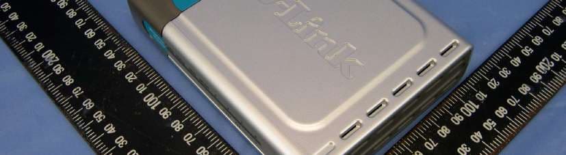
Click to zoom
Application Details
- Equipment Class
- DTS - Digital Transmission System
- Date of Grant
- Oct 11, 2005
- Application Purpose
- Original Equipment
- Date of Application
- Oct 11, 2005
- Equipment Note
- IEEE802.11g Wireless Router
- Frequency Range
- 2412.00000000 - 2462.00000000
- Company
- D-Link Corporation
- Country
- United States
Documents & Files
Document Text
Text extracted from the exhibit documents filed with the FCC. Open a document above to read the original.
Users Manual
802.11g/ 2.4 GHz Manual Building Networks for People Wireless Router D-Link AirPlus G DI-524 TM 2 Contents Package Contents ................................................................................3 Introduction ...........................................................................................4 Wireless Basics ....................................................................................8 Getting Started ....................................................................................11 Using the Configuration Menu ............................................................12 Networking Basics ..............................................................................40 Troubleshooting ..................................................................................55 Technical Specifications ..................................................................... 62 Frequently Asked Questions ..............................................................65 Contacting Technical Support .............................................................93 Warranty and Registration ..................................................................94 3 Internet Explorer Version 6.0 or Netscape Navigator Version 7.0 and Above Contents of Package: D-Link AirPlus G DI-524 802.11/2.4GHz Wireless Router Power Adapter-DC 5V, 2.5A Manual and Warranty on CD Quick Installation Guide Ethernet Cable (All the DI-524’s Ethernet ports are Auto-MDIX) Computers with Windows, Macintosh, or Linux-based operating systems with an installed Ethernet adapter Package Contents Note: Using a power supply with a different voltage rating than the one included with the DI-524 will cause damage and void the warranty for this product. If any of the above items are missing, please contact your reseller. System Requirements for Configuration: Ethernet-Based Cable or DSL Modem 4 Introduction The D-Link AirPlus G DI-524 High-Speed Wireless Router is an 802.11g high- performance, wireless router that supports high-speed wireless networking at home, at work or in public places. Unlike most routers, the DI-524 provides data transfers at up to 108 Mbps (compared to the standard 54 Mbps) when used with other D-Link AirPlus G products. The 802.11g standard is backwards compatible with 802.11b products. This means that you do not need to change your entire network to maintain connectivity. You may sacrifice some of 802.11g’s speed when you mix 802.11b and 802.11g devices, but you will not lose the ability to communicate when you incorporate the 802.11g standard into your 802.11b network. You may choose to slowly change your network by gradually replacing the 802.11b devices with 802.11g devices . In addition to offering faster data transfer speeds when used with other 802.11g products, the DI-524 has the newest, strongest, most advanced security features available today. When used with other 802.11g WPA (WiFi Protected Access) and 802.1x compatible products in a network with a RADIUS server, the security features include: WPA: Wi-Fi Protected Access authorizes and identifies users based on a secret key that changes automatically at a regular interval. WPA uses TKIP (Temporal Key Integrity Protocol) to change the temporal key every 10,000 packets (a packet is a kind of message transmitted over a network.) This insures much greater security than the standard WEP security. (By contrast, the older WEP encryption required the keys to be changed manually.) 802.1x: Authentication is a first line of defense against intrusion. In the Authentication process the server verifies the identity of the client attempting to connect to the network. Unfamiliar clients would be denied access. For home users that will not incorporate a RADIUS server in their network, the security for the DI-524, used in conjunction with other 802.11g products, will still be much stronger than ever before. Utilizing the Pre Shared Key mode of WPA, the DI-524 will obtain a new security key every time it connects to the 802.11g network. You only need to input your encryption information once in the configuration menu. No longer will you have to manually input a new WEP key frequently to ensure security, with the DI-524, you will automatically receive a new key every time you connect, vastly increasing the safety of your communications. 5 Connections All Ethernet Ports (WAN and LAN) are auto MDI/MDIX, meaning you can use either a straight-through or a crossover Ethernet cable. The Auto MDI/ MDIX WAN port is the connection for the Ethernet cable to the Cable or DSL modem Auto MDI/MDIX LAN ports automatically sense the cable type when connecting to Ethernet-enabled computers. Receptor for the Power Adapter Pressing the Reset Button restores the router to its original factory default settings. 6 LEDs WLAN LED A solid light indicates that the wireless segment is ready. This LED blinks during wireless data transmission POWER LED A solid light indicates a proper connection to the power supply LOCAL NETWORK LED A solid light indicates a connection to an Ethernet-enabled computer on ports 1-4. This LED blinks during data transmission WAN LED A solid light indicates connection on the WAN port. This LED blinks during data transmission STATUS A blinking light indicates that the DI-524 is ready 7 Features WPA (Wi Fi Protected Access) authorizes and identifies users based on a secret key that changes automatically at a regular interval, for example: 802.1x Authentication in conjunction with the RADIUS server verifies the identity of would be clients TKIP (Temporal Key Integrity Protocol), in conjunction with a RADIUS server, changes the temporal key every 10,000 packets, ensuring greater security Pre Shared Key mode means that the home user, without a RADIUS server, will obtain a new security key every time the he or she connects to the network, vastly improving the safety of communications on the network. Backwards compatible with the 802.…
Text truncated - open the document above for the full version.
Users Manual
21 Example #2: If you have an FTP server that you wanted Internet users to access by WAN port 2100 and only during the weekends, you would need to enable it as such. FTP server is on LAN computer 192.168.0.30. FTP uses port 21, TCP. Name: FTP Server Private IP: 192.168.0.30 Protocol Type: TCP Private Port: 21 Public Port: 2100 Schedule: From: 01:00AM to 01:00AM, Sat to Sun Using the Configuration Menu (continued) Advanced > Virtual Server continued Click on this icon to edit the virtual service Click on this icon to delete the virtual service All Internet users who want to access this FTP Server must connect to it from port 2100. This is an example of port redirection and can be useful in cases where there are many of the same servers on the LAN network. 22 Using the Configuration Menu (continued) Advanced > Applications Some applications require multiple connections, such as Internet gaming, video conferencing, Internet telephony and others. These applications have difficulties working through NAT (Network Address Translation). Special Applications makes some of these applications work with the DI-524. If you need to run applications that require multiple connections, specify the port normally associated with an application in the “Trigger Port” field, select the protocol type as TCP or UDP, then enter the public ports associated with the trigger port to open them for inbound traffic. The DI-524 provides some predefined applications in the table on the bottom of the web page. Select the application you want to use and enable it. Note! Only one PC can use each Special Application tunnel. Name: This is the name referencing the special application. Trigger Port: This is the port used to trigger the application. It can be either a single port or a range of ports. Trigger Type: This is the protocol used to trigger the special application. Public Port: This is the port number on the WAN side that will be used to access the application. You may define a single port or a range of ports. You can use a comma to add multiple ports or port ranges. Public Type: This is the protocol used for the special application. 23 Using the Configuration Menu (continued) Advanced > Filters > IP Filters Filters are used to deny or allow LAN (Local Area Network) computers from accessing the Internet. The DI-524 can be setup to deny internal computers by their IP or MAC addresses. The DI-524 can also block users from accessing restricted web sites. This is the schedule of time when the IP Filter will be enabled. Schedule: Select the protocol type Protocol Type: IP Filter is used to deny LAN IP addresses from accessing the Internet. You can deny specific port numbers or all ports for the specific IP address. IP Filters: The single port or port range that will be denied access to the Internet. Port Range: The IP address of the LAN computer that will be denied access to the Internet. IP Address: 24 Using the Configuration Menu (continued) Advanced > Filters > URL Blocking Filters- URL Blocking is used to deny LAN computers from accessing specific web sites by the URL. A URL is a specially formatted text string that defines a location on the Internet. If any part of the URL contains the blocked word, the site will not be accessible and the web page will not display. To use this feature, enter the text string to be blocked and click Apply. The text to be blocked will appear in the list. To delete the text, just highlight it and click Delete. Select the filter you wish to use; in this case, URL Blocking was chosen. Keywords- Enter the keywords in this field. Block URLs which contain keywords listed below. URL Blocking- Select Enabled or Disabled. 25 Using the Configuration Menu Advanced > Filters > MAC Filters Use MAC (Media Access Control) Filters to allow or deny LAN (Local Area Network) computers by their MAC addresses from accessing the Network. You can either manually add a MAC address or select the MAC address from the list of clients that are currently connected to the Broadband Router. MAC Filters- Choose Disable MAC filters; allow MAC addresses listed below; or deny MAC addresses listed below. Filters- Name- Enter the name here. MAC Address- Enter the MAC Address. DHCP Client- Select a DHCP client from the pull-down list; click Clone to copy that MAC Address. Select the filter you wish to use; in this case, MAC filters was chosen. (continued) 26 Using the Configuration Menu Advanced > Filters > Domain Blocking Filters- Domain Blocking- Blocked Domains- Permitted Domains- Domain Blocking is used to allow or deny LAN (Local Area Network) computers from accessing specific domains on the Internet. Domain blocking will deny all requests to a specific domain such as http and ftp. It can also allow computers to access specific sites and deny all other sites. Select the filter you wish to use; in this case, Domain Block- ing was chosen. Disabled- Allow- Deny- Enter the Permitted Domains in this field Enter the Blocked Domains in this field Select Disabled to disable Domain Blocking Allows users to access all domains except Blocked Domains Denies users access to all domains except Permitted Domains (continued) 27 Using the Configuration Menu (continued) Advanced > Firewall Firewall Rules is an advanced feature used to deny or allow traffic from passing through the DI-524. It works in the same way as IP Filters with additional settings. You can create more detailed access rules for the DI-524. When virtual services are created and enabled, it will also display in Firewall Rules. Firewall Rules contain all network firewall rules pertaining to IP (Internet Protocol). In the Firewall Rules List at the bottom of the screen, the priorities of the rules are from top (highest priority) to bottom (lowest priority.) Note: The DI-524 MAC Address filtering rules have precedence over the Firewall Rules. Firewall Rules- Enable or disable the Firewall Name- Enter the name Action- Allow or Deny Source- Enter the IP Address range Schedul…
Text truncated - open the document above for the full version.
Users Manual
31 Using the Configuration Menu (continued) Tools> Admin At this page, the DI-524 administrator can change the system password. There are two accounts that can access the Broadband Router’s Web-Management interface. They are admin and user. Admin has read/write access while user has read-only access. User can only view the settings but cannot make any changes. Remote Management- Remote management allows the DI-524 to be configured from the Internet by a web browser. A username and password is still required to ac - cess the Web-Management interface. In general, only a member of your network can browse the built-in web pages to perform Administrator tasks. This feature enables you to perform Administrator tasks from the remote (Internet) host. IP Address- The Internet IP address of the computer that has access to the Broad- band Router. If you input an asterisk (*) into this field, then any computer will be able to access the Router. Putting an asterisk (*) into this field would present a security risk and is not recommended. Port- The port number used to access the Broadband Router. Example- http://x.x.x.x:8080 where x.x.x.x is the WAN IP address of the Broadband Router and 8080 is the port used for the Web-Mangement interface. Administrator- Password- admin is the Administrator login name Enter the password and enter again to confirm User- Password- user is the User login name Enter the password and enter again to confirm 32 Using the Configuration Menu (continued) Tools > Time Time Zone- Set Device Date and Time: To manually input the time. Enter the values in these fields for the Year, Month, Day, Hour, Minute, and Second. Daylight Saving- To select Daylight Saving time manually, select enabled or disabled, and enter a start date and an end date for daylight saving time. Set the Time- To manually input the time, enter the values in these fields for the Year, Month, Day, Hour, Minute, and Second. Click Set Time . Default NTP Server- NTP is short for Network Time Protocol. NTP synchronizes computer clock times in a network of computers. This field is optional. 33 Using the Configuration Menu (continued) Tools > System The current system settings can be saved as a file onto the local hard drive. The saved file or any other saved setting file can be loaded back on the Broadband Router. To reload a system settings file, click on Browse to browse the local hard drive and locate the system file to be used. You may also reset the Broadband Router back to factory settings by clicking on Restore. Click Save to save the current settings to the local Hard Drive Click Browse to find the settings, then click Load Save Settings to Local Hard Drive- Load Settings from Local Hard Drive- Restore to Factory Default Settings- Click Restore to restore the factory default settings 34 Using the Configuration Menu (continued) Tools > Firmware You can upgrade the firmware of the Router here. Make sure the firmware you want to use is on the local hard drive of the computer. Click on Browse to browse the local hard drive and locate the firmware to be used for the update. Please check the D-Link support site for firmware updates at http://support.dlink.com. You can download firmware upgrades to your hard drive from the D-Link support site. Firmware Upgrade- Browse- Click on the link in this screen to find out if there is an up- dated firmware; if so, download the new firmware to your hard After you have downloaded the new firmware, click Browse in this window to locate the firmware update on your hard drive. Click Apply to complete the firmware upgrade. 35 Using the Configuration Menu (continued) Tools > Misc Ping Test- Restart Device- Block WAN Ping- Discard Ping from WAN side- VPN Pass Through- PPTP- select Enabled or Disabled IPSec- select Enabled or Disabled The Ping Test is used to send Ping packets to test if a computer is on the Internet. Enter the IP Address that you wish to Ping, and click Ping If you choose to block WAN Ping, the WAN IP Address of the DI-524 will not respond to pings. Blocking the Ping may provide some extra security from hackers. The DI-524 supports VPN (Virtual Private Network) pass-through for both PPTP (Point-to-Point Tunneling Protocol) and IPSec (IP Security). Once VPN pass-through is enabled, there is no need to open up virtual services. Multiple VPN connections can be made through the DI-524. This is useful when you have many VPN clients on the LAN network. Click Reboot to restart the DI-524 Click Enabled to block the WAN ping UPNP- To use the Universal Plug and Play feature click on Enabled. UPNP pro- vides compatibility with networking equipment, software and peripherals of the over 400 vendors that cooperate in the Plug and Play forum. 36 Using the Configuration Menu (continued) Status > Device Info This page displays the current information for the DI-524. It will display the LAN, WAN and MAC address information. If your WAN connection is set up for a Dynamic IP address then a Release button and a Renew button will be displayed. Use Release to disconnect from your ISP and use Renew to connect to your ISP. If your WAN connection is set up for PPPoE, a Connect button and a Disconnect but- ton will be displayed. Use Disconnect to drop the PPPoE connection and use Connect to establish the PPPoE connection. This window will show the DI-524’s working status: IP Address: WAN/Public IP Address Subnet Mask: WAN/Public Subnet Mask Gateway: WAN/Public Gateway IP Address Domain Name Server: WAN/Public DNS IP Address WAN Status: WAN Connection Status Wireless IP Address: LAN/Private IP Address of the DI-524 Subnet Mask: LAN/Private Subnet Mask of the DI-524 WAN LAN MAC Address: Displays the MAC address SSID: Displays the current SSID Channel: Displays the current channel WEP: indicates whether WEP is enabled or disabled 37 The Broadband Router keeps a running log of events and activities occurring on the Router. If the device is rebooted, the logs are automatically cleared. You may save…
Text truncated - open the document above for the full version.
Users Manual
41 Please follow all the instructions in this window: Networking Basics Click Next In the following window, select the best description of your computer. If your computer connects to the internet through a gateway/router, select the second option as shown. Click Next 42 Enter a Computer description and a Computer name (optional.) Networking Basics Click Next Enter a Workgroup name. All computers on your network should have the same Workgroup name. Click Next 43 Please wait while the Network Setup Wizard applies the changes. Networking Basics When the changes are complete, click Next. Please wait while the Network Setup Wizard configures the computer. This may take a few minutes. 44 Networking Basics In the window below, select the option that fits your needs. In this example, Create a Network Setup Disk has been selected. You will run this disk on each of the computers on your network. Click Next. Insert a disk into the Floppy Disk Drive, in this case drive A. Click Next. 45 Networking Basics Please read the information under Here’s how in the screen below. After you complete the Network Setup Wizard you will use the Network Setup Disk to run the Network Setup Wizard once on each of the computers on your network. To continue click Next. 46 Networking Basics Please read the information on this screen, then click Finish to complete the Network Setup Wizard . The new settings will take effect when you restart the computer. Click Yes to restart the computer. You have completed configuring this computer. Next, you will need to run the Network Setup Disk on all the other computers on your network. After running the Network Setup Disk on all your computers, your new wireless network will be ready to use. 47 Networking Basics Naming your Computer To name your computer, please follow these directions:In Windows XP: Click Start (in the lower left corner of the screen) Right-click on My Computer Select Properties and click Select the Computer Name Tab in the System Properties window. You may enter a Computer Description if you wish; this field is optional. To rename the computer and join a domain, Click Change. 48 Networking Basics Naming your Computer In this window, enter the Computer name Select Workgroup and enter the name of the Workgroup All computers on your network must have the same Workgroup name. Click OK Checking the IP Address in Windows XP The wireless adapter-equipped computers in your network must be in the same IP Ad- dress range (see Getting Started in this manual for a definition of IP Address Range.) To check on the IP Address of the adapter, please do the following: Right-click on the Local Area Connection icon in the task bar Click on Status 49 Networking Basics Checking the IP Address in Windows XP This window will appear. Click the Support tab Click Close Assigning a Static IP Address in Windows XP/2000 Note: Residential Gateways/Broadband Routers will automatically assign IP Addresses to the computers on the network, using DHCP (Dynamic Host Configuration Protocol) technology. If you are using a DHCP-capable Gateway/Router you will not need to assign Static IP Addresses. If you are not using a DHCP capable Gateway/Router, or you need to assign a Static IP Address, please follow these instructions: Go to Start Double-click on Control Panel 50 Networking Basics Assigning a Static IP Address in Windows XP/2000 Double-click on Network Connections Double-click on Properties Right-click on Local Area Connections 51 Input your IP address and subnet mask. (The IP Addresses on your network must be within the same range. For example, if one computer has an IP Address of 192.168.0.2, the other computers should have IP Addresses that are sequential, like 192.168.0.3 and 192.168.0.4. The subnet mask must be the same for all the computers on the network.) Networking Basics Assigning a Static IP Address in Windows XP/2000 Input your DNS server addresses. (Note: If you are entering a DNS server, you must enter the IP Address of the Default Gateway.) The DNS server information will be supplied by your ISP (Internet Service Provider.) Click OK Click on Internet Protocol (TCP/IP) Click Properties 52 Networking Basics Assigning a Static IP Address with Macintosh OSX Go to the Apple Menu and select System Preferences cClick on Network Select Built-in Ethernet in the Show pull-down menu Select Manually in the Configure pull-down menu Input the Static IP Address , the Subnet Mask and the Router IP Address in the appropriate fields Click Apply Now 53 Networking Basics Selecting a Dynamic IP Address with Macintosh OSX Go to the Apple Menu and select System Preferences Click on Network Select Built-in Ethernet in the Show pull-down menu Select Using DHCP in the Configure pull-down menu Click Apply Now The IP Address, Subnet mask, and the Router’s IP Address will appear in a few seconds 54 Networking Basics Checking the Wireless Connection by Pinging in Windows XP and 2000 Checking the Wireless Connection by Pinging in Windows Me and 98 Go to Start > Run > type cmd. A window similar to this one will appear. Type ping xxx.xxx.xxx. xxx, where xxx is the IP Address of the Wireless Router or Access Point. A good wireless connection will show four replies from the Wireless Router or Acess Point, as shown. Go to Start > Run > type command. A window similar to this will appear. Type ping xxx.xxx. xxx.xxx where xxx is the IP Address of the Wireless Router or Access Point. A good wireless connection will show four replies from the wireless router or access point, as shown. 55 Troubleshooting This Chapter provides solutions to problems that can occur during the installation and operation of the DI-524 Wireless Broadband Router. We cover various aspects of the network setup, including the network adapters. Please read the following if you are having problems. Note: If you have changed the default IP Address, make sure to ping the correc…
Text truncated - open the document above for the full version.
Users Manual
56 2. The wireless client cannot access the Internet in the Infrastructure mode. Make sure the wireless client is associated and joined with the correct Access Point. To check this connection: Right-click on the Local Area Connection icon in the taskbar> select View Available Wireless Networks. The Connect to Wireless Network screen will appear. Please make sure you have selected the correct available network, as shown in the illustrations below. Troubleshooting Check that the IP Address assigned to the wireless adapter is within the same IP Address range as the access point and gateway. (Since the DI-524 has an IP Address of 192.168.0.1, wireless adapters must have an IP Address in the same range, e.g., 192.168.0.x. Each device must have a unique IP Address; no two devices may have the same IP Address. The subnet mask must be the same for all the computers on the network.) To check the IP Address assigned to the wireless adapter, double-click on the Local Area Connection icon in the taskbar > select the Support tab and the IP Address will be displayed. (Please refer to Checking the IP Address in the Networking Basics section of this manual.) If it is necessary to assign a Static IP Address to the wireless adapter, please refer to the appropriate section in Networking Basics. If you are entering a DNS Server address you must also enter the Default Gateway Address. (Remember that if you have a DHCP-capable router, you will not need to assign a Static IP Address. See Networking Basics: Assigning a Static IP Address. ) 57 Troubleshooting 3. Check that the drivers for the network adapters are installed properly. You may be using different network adapters than those illustrated here, but this procedure will remain the same, regardless of the type of network adapters you are using. Click Device Manager Select the Hardware Tab Go to Start > My Computer > Properties 58 Troubleshooting Double-click on Network Adapters Right-click on D-Link AirPlus DWL-G650 Wireless Cardbus Adapter (In this example we use the DWL-G650; you may be using other network adapters, but the procedure will remain the same.) Select Properties to check that the drivers are installed properly Look under Device Status to check that the device is working properly Click OK D-Link AirPlus DWL-G650 Wireless Cardbus Adapter D-Link AirPlus DWL-G650 Wireless Cardbus Adapter D-Link AirPlus DWL-G650 59 Troubleshooting 4. What variables may cause my wireless products to lose reception? D-Link products let you access your network from virtually anywhere you want. However, the positioning of the products within your environment will affect the wireless range. Please refer to Installation Considerations in the Wireless Basics section of this manual for further information about the most advantageous placement of your D-Link wireless products. 5. Why does my wireless connection keep dropping? 6. Why can’t I get a wireless connection? If you have enabled Encryption on the DI-524, you must also enable encryption on all wireless clients in order to establish a wireless connection. Make sure that the SSID on the Router and the Wireless Client are exactly the same. If they are not, wireless connection will not be established. For 802.11b, the Encryption settings are: 64, 128, or 256 bit. Make sure that the encryption bit level is the same on the Router and the Wireless Client. Move the DI-524 and the wireless client into the same room and then test the wireless connection. Disable all security settings. (WEP, MAC Address Control) Antenna Orientation- Try different antenna orientations for the DI-524. Try to keep the antenna at least 6 inches away from the wall or other objects. If you are using 2.4GHz cordless phones, X-10 equipment or other home security systems, ceiling fans, and lights, your wireless connection will degrade dramatically or drop altogether. Try changing the Channel on your Router, Access Point and Wireless adapter to a different Channel to avoid interference. Keep your product away (at least 3-6 feet) from electrical devices that generate RF noise, like microwaves, Monitors, electric motors, etc. 60 Troubleshooting 6. Why can’t I get a wireless connection? (continued) Turn off your DI-524 and the client. Turn the DI-524 back on again, and then turn on the client. Check that the LED indicators are indicating normal activity. If not, check that the AC power and Ethernet cables are firmly connected. Make sure that all devices are set to Infrastructure mode. Check that the IP Address, subnet mask, gateway and DNS settings are cor- rectly entered for the network. If you are using 2.4GHz cordless phones, X-10 equipment or other home se- curity systems, ceiling fans, and lights, your wireless connection will degrade dramatically or drop altogether. Try changing the Channel on your DI-524, and on all the devices in your network to avoid interference. Keep your product away (at least 3-6 feet) from electrical devices that generate RF noise, like microwaves, Monitors, electric motors, etc. 7. I forgot my encryption key. Reset the DI-524 to its factory default settings and restore the other devices on your network to their default settings. You may do this by pressing the Reset button on the back of the unit. You will lose the current configuration settings. 61 8. Resetting the DI-524 to Factory Default Settings After you have tried other methods for troubleshooting your network, you may choose to Reset the DI-524 to the factory default settings. Remember that D-Link AirPro products network together, out of the box, at the factory default settings. To hard-reset the DI-524 to Factory Default Settings, please do the following: Troubleshooting After the DI-524 reboots (this may take a few minutes) it will be reset to the factory Default settings Use a paper clip to press the Reset button Hold for about 10 seconds and then release Locate the Reset button on the back of the DI-524 Res…
Text truncated - open the document above for the full version.
Contact Information
Applicant
Brett Adair(General Counsel)
Technical Contact
Advance Data Technology CorporationEric Lin
[email protected]886-3-593-5343
81-1 Luliaoken, 9th Lin, Wulung Tsuen Chiunglin · Hsinchu · Taiwan
Non-Technical Contact
Advance Data Technology CorporationEric Lin
[email protected]886-3-593-5343
Test Firm
Bureau Veritas CPS (H.K.) Ltd. Taoyuan BranchRichard Chen
Technical Specifications
| # | Rule Parts | Frequency Range | Power Output |
|---|---|---|---|
| 1 | 15C | 2.41 GHz - 2.46 GHz | 208.00 mW |
Other Applications from D-Link Corporation

KA2CS6012A1
Jul 07, 20262K Fixed Indoor Cloud Camera, 2K Fixed Indoor Wi-Fi Camera
Equipment Class
DTS - Digital Transmission SystemKA2AE65UA1
Mar 02, 2026Wi-Fi 7 BE6500 USB 3.0 Dongle
Equipment Class
NII - Unlicensed National Information Infrastructure TXKA2APE9560A1
Nov 17, 2025BE9500 Celling mount Access Point
Equipment Class
6ID - 15E 6 GHz Low Power Indoor Access PointKA2AX9UA1
Dec 04, 2024AX900 Wi-Fi 6 USB Adapter, Wi-Fi 6 AX900 USB 2.0 Dongle
Equipment Class
DSS - Part 15 Spread Spectrum TransmitterKA2AC13UA1
Dec 04, 2024AC1300 Wi-Fi 5 USB Adapter, Wi-Fi 5 AC1300 USB 2.0 Dongle
Equipment Class
DTS - Digital Transmission System