KA2DI524UPWIRELESS BROADBAND ROUTER
D-Link Corporation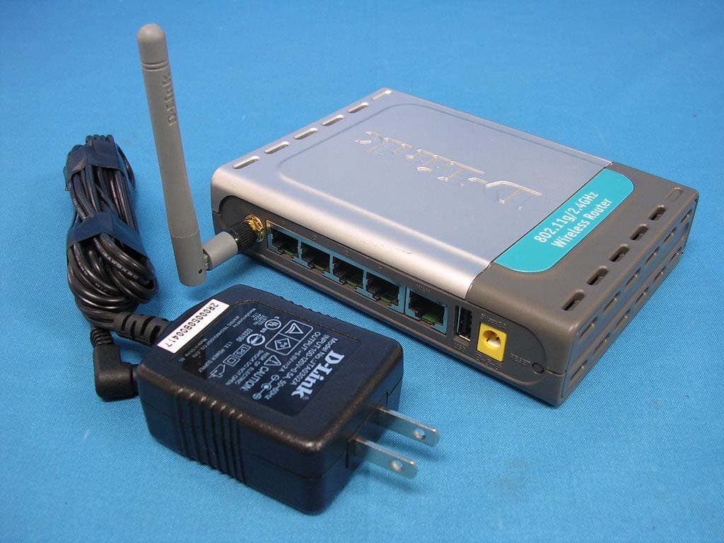
Click to zoom
Application Details
- Equipment Class
- DTS - Digital Transmission System
- Date of Grant
- Jun 01, 2005
- Application Purpose
- Original Equipment
- Date of Application
- Jun 01, 2005
- Equipment Note
- WIRELESS BROADBAND ROUTER
- Frequency Range
- 2412.00000000 - 2462.00000000
- Company
- D-Link Corporation
- Country
- United States
Documents & Files
Document Text
Text extracted from the exhibit documents filed with the FCC. Open a document above to read the original.
Users Manual
802.11g/ 2.4 GHz Manual Building Networks for People Wireless Broadband Router with Print Server D-Link AirPlus G DI-524UP TM 2 Contents Package Contents ................................................................................3 Introduction ...........................................................................................4 Wireless Basics ....................................................................................8 Getting Started ....................................................................................11 Using the Configuration Menu ............................................................12 Installing the Print Server Software ....................................................40 Networking Basics ..............................................................................42 Troubleshooting ..................................................................................57 Technical Specifications .....................................................................64 Frequently Asked Questions ..............................................................67 Contacting Technical Support .............................................................95 Warranty and Registration ..................................................................96 3 Internet Explorer Version 6.0 or Netscape Navigator Version 7.0 and Above Contents of Package: D-Link AirPlus G DI-524UP 802.11/2.4GHz Wireless Router Power Adapter-DC 5V, 2A Manual and Warranty on CD Quick Installation Guide Ethernet Cable (All the DI-524UP’s Ethernet ports are Auto-MDIX) Computers with Windows, Macintosh, or Linux-based operating systems with an installed Ethernet adapter Package Contents Note: Using a power supply with a different voltage rating than the one included with the DI-524UP will cause damage and void the warranty for this product. If any of the above items are missing, please contact your reseller. System Requirements for Configuration: Ethernet-Based Cable or DSL Modem 4 Introduction The D-Link AirPlus G DI-524UP High-Speed Wireless Router is an 802.11g high- performance, wireless router that supports high-speed wireless networking at home, at work or in public places. Unlike most routers, the DI-524UP provides data transfers at up to 108 Mbps (compared to the standard 54 Mbps) when used with other D-Link AirPlus G products. The 802.11g standard is backwards compatible with 802.11b products. This means that you do not need to change your entire network to maintain connectivity. You may sacrifice some of 802.11g’s speed when you mix 802.11b and 802.11g devices, but you will not lose the ability to communicate when you incorporate the 802.11g standard into your 802.11b network. You may choose to slowly change your network by gradually replacing the 802.11b devices with 802.11g devices . In addition to offering faster data transfer speeds when used with other 802.11g products, the DI-524UP has the newest, strongest, most advanced security features available today. When used with other 802.11g WPA (WiFi Protected Access) and 802.1x compatible products in a network with a RADIUS server, the security features include: WPA: Wi-Fi Protected Access authorizes and identifies users based on a secret key that changes automatically at a regular interval. WPA uses TKIP (Temporal Key Integrity Protocol) to change the temporal key every 10,000 packets (a packet is a kind of message transmitted over a network.) This insures much greater security than the standard WEP security. (By contrast, the older WEP encryption required the keys to be changed manually.) 802.1x: Authentication is a first line of defense against intrusion. In the Authentication process the server verifies the identity of the client attempting to connect to the network. Unfamiliar clients would be denied access. For home users that will not incorporate a RADIUS server in their network, the security for the DI-524UP, used in conjunction with other 802.11g products, will still be much stronger than ever before. Utilizing the Pre Shared Key mode of WPA, the DI-524UP will obtain a new security key every time it connects to the 802.11g network. You only need to input your encryption information once in the configuration menu. No longer will you have to manually input a new WEP key frequently to ensure security, with the DI-524UP, you will automatically receive a new key every time you connect, vastly increasing the safety of your communications. 5 Connections All Ethernet Ports (WAN and LAN) are auto MDI/MDIX, meaning you can use either a straight-through or a crossover Ethernet cable. The Auto MDI/ MDIX WAN port is the connection for the Ethernet cable to the Cable or DSL modem Auto MDI/MDIX LAN ports automatically sense the cable type when connecting to Ethernet-enabled computers. Receptor for the Power Adapter Pressing the Reset Button restores the router to its original factory default settings. USB Printer Port Connect to the printer using a USB cable. This feature is used to share the printer on the network. 6 LEDs WLAN LED A solid light indicates that the wireless segment is ready. This LED blinks during wireless data transmission POWER LED A solid light indicates a proper connection to the power supply LOCAL NETWORK LED A solid light indicates a connection to an Ethernet-enabled computer on ports 1-4. This LED blinks during data transmission WAN LED A solid light indicates connection on the WAN port. This LED blinks during data transmission STATUS A blinking light indicates that the DI-524UP is ready 7 Features WPA (Wi Fi Protected Access) authorizes and identifies users based on a secret key that changes automatically at a regular interval, for example: 802.1x Authentication in conjunction with the RADIUS server verifies the identity of would be clients TKIP (Temporal Key Integrity Protocol), in conjunction with a RADIUS server, changes the temporal key every 10,000 packets, ensuring greater sec…
Text truncated - open the document above for the full version.
Users Manual
50 Networking Basics Naming your Computer In this window, enter the Computer name Select Workgroup and enter the name of the Workgroup All computers on your network must have the same Workgroup name. Click OK Checking the IP Address in Windows XP The wireless adapter-equipped computers in your network must be in the same IP Ad- dress range (see Getting Started in this manual for a definition of IP Address Range.) To check on the IP Address of the adapter, please do the following: Right-click on the Local Area Connection icon in the task bar Click on Status 51 Networking Basics Checking the IP Address in Windows XP This window will appear. Click the Support tab Click Close Assigning a Static IP Address in Windows XP/2000 Note: Residential Gateways/Broadband Routers will automatically assign IP Addresses to the computers on the network, using DHCP (Dynamic Host Configuration Protocol) technology. If you are using a DHCP-capable Gateway/Router you will not need to assign Static IP Addresses. If you are not using a DHCP capable Gateway/Router, or you need to assign a Static IP Address, please follow these instructions: Go to Start Double-click on Control Panel 52 Networking Basics Assigning a Static IP Address in Windows XP/2000 Double-click on Network Connections Double-click on Properties Right-click on Local Area Connections 53 Input your IP address and subnet mask. (The IP Addresses on your network must be within the same range. For example, if one computer has an IP Address of 192.168.0.2, the other computers should have IP Addresses that are sequential, like 192.168.0.3 and 192.168.0.4. The subnet mask must be the same for all the computers on the network.) Networking Basics Assigning a Static IP Address in Windows XP/2000 Input your DNS server addresses. (Note: If you are entering a DNS server, you must enter the IP Address of the Default Gateway.) The DNS server information will be supplied by your ISP (Internet Service Provider.) Click OK Click on Internet Protocol (TCP/IP) Click Properties 54 Networking Basics Assigning a Static IP Address with Macintosh OSX Go to the Apple Menu and select System Preferences cClick on Network Select Built-in Ethernet in the Show pull-down menu Select Manually in the Configure pull-down menu Input the Static IP Address, the Subnet Mask and the Router IP Address in the appropriate fields Click Apply Now 55 Networking Basics Selecting a Dynamic IP Address with Macintosh OSX Go to the Apple Menu and select System Preferences Click on Network Select Built-in Ethernet in the Show pull-down menu Select Using DHCP in the Configure pull-down menu Click Apply Now The IP Address, Subnet mask, and the Router’s IP Address will appear in a few seconds 56 Networking Basics Checking the Wireless Connection by Pinging in Windows XP and 2000 Checking the Wireless Connection by Pinging in Windows Me and 98 Go to Start > Run > type cmd. A window similar to this one will appear. Type ping xxx.xxx.xxx. xxx, where xxx is the IP Address of the Wireless Router or Access Point. A good wireless connection will show four replies from the Wireless Router or Acess Point, as shown. Go to Start > Run > type command. A window similar to this will appear. Type ping xxx.xxx. xxx.xxx where xxx is the IP Address of the Wireless Router or Access Point. A good wireless connection will show four replies from the wireless router or access point, as shown. 57 Troubleshooting This Chapter provides solutions to problems that can occur during the installation and operation of the DI-524UP Wireless Broadband Router. We cover various aspects of the network setup, including the network adapters. Please read the following if you are having problems. Note: If you have changed the default IP Address, make sure to ping the correct IP Ad- dress assigned to the DI-524UP. Note: It is recommended that you use an Ethernet connection to configure the DI-524UP Wireless Broadband Router. 1. The computer used to configure the DI-524UP cannot access the Configuration menu. Check that the Ethernet LED on the DI-524UP is ON. If the LED is not ON, check that the cable for the Ethernet connection is securely inserted. Check that the Ethernet Adapter is working properly. Please see item 3 (Check that the drivers for the network adapters are installed properly) in this Troubleshooting section to check that the drivers are loaded properly. Check that the IP Address is in the same range and subnet as the DI-524UP. Please see Checking the IP Address in Windows XP in the Networking Basics section of this manual. Note: The IP Address of the DI-524UP is 192.168.0.1. All the computers on the network must have a unique IP Address in the same range, e.g., 192.168.0.x. Any computers that have identical IP Addresses will not be visible on the network. They must all have the same subnet mask, e.g., 255.255.255.0 Do a Ping test to make sure that the DI-524UP is responding. Go to Start>Run>Type Command>Type ping 192.168.0.1. A successful ping will show four replies. 58 2. The wireless client cannot access the Internet in the Infrastructure mode. Make sure the wireless client is associated and joined with the correct Access Point. To check this connection: Right-click on the Local Area Connection icon in the taskbar> select View Available Wireless Networks. The Connect to Wireless Network screen will appear. Please make sure you have selected the correct available network, as shown in the illustrations below. Troubleshooting Check that the IP Address assigned to the wireless adapter is within the same IP Address range as the access point and gateway. (Since the DI-524UP has an IP Address of 192.168.0.1, wireless adapters must have an IP Address in the same range, e.g., 192.168.0.x. Each device must have a unique IP Address; no two devices may have the same IP Address. The subnet mask must be the same for all the computers on the network.) To check the IP Ad…
Text truncated - open the document above for the full version.
Block Diagram
CPU Flash SDRAM SWITCH WAN*1 LAN*4 MII 2 MII 1 DI-524UP Block Diagram Crystal 25MHz MiniPCI Wireless LAN 25MHz Transform USB RF Module
External Photos
Report No: 055H049-F-R02-T Page: 66 of 73 Version:1.0 Attachement ¾ EUT Photograph (1) EUT Photo (2) EUT Photo
ID Label/Location Info
2F, No. 233-2, Pao-Chiao Road, Hsin-Tien, Taipei, Taiwan, R.O.C. Tel: 886-2-2910-2626 Fax: 886-2-2910-1515 http://www.dlinktw.com.tw FCC ID.: KA2DI524UP FCC ID and DoC Label The FCC ID and DoC Label will be placed on the equipment as shown in the photograph below. Wireless Broadband Router Model No.: DI-524UP F F C C C C I I D D : : KA2DI524UP This device complies with Part 15 of the FCC Rules. Operation is subject to the following two conditions: (1) this device may not cause harmful interference and (2) this device must accept any interference received, including interference that may cause undesired operation. S/N: Made in Taiwan Trade name: D-Link Model number.: DI-524UP
ID Label/Location Info
2F, No. 233-2, Pao-Chiao Road, Hsin-Tien, Taipei, Taiwan, R.O.C. Tel: 886-2-2910-2626 Fax: 886-2-2910-1515 http://www.dlinktw.com.tw FCC ID.: KA2DI524UP FCC ID and DoC Label The FCC ID and DoC Label will be placed on the equipment as shown in the photograph below. Wireless Broadband Router Model No.: DI-524UP F F C C C C I I D D : : KA2DI524UP This device complies with Part 15 of the FCC Rules. Operation is subject to the following two conditions: (1) this device may not cause harmful interference and (2) this device must accept any interference received, including interference that may cause undesired operation. S/N: Made in Taiwan Trade name: D-Link Model number.: DI-524UP
Internal Photos
Report No: 055H049-F-R02-T Page: 67 of 73 Version:1.0 (3) EUT Photo (4) EUT Photo Report No: 055H049-F-R02-T Page: 68 of 73 Version:1.0 (5) EUT Photo (6) EUT Photo Report No: 055H049-F-R02-T Page: 69 of 73 Version:1.0 (7) EUT Photo Report No: 055H049-F-R02-T Page: 70 of 73 Version:1.0 (8) EUT Photo Report No: 055H049-F-R02-T Page: 71 of 73 Version:1.0 (9) EUT Photo Report No: 055H049-F-R02-T Page: 72 of 73 Version:1.0 (10) EUT Photo (11) EUT Photo Report No: 055H049-F-R02-T Page: 73 of 73 Version:1.0 (12) EUT Photo
Operational Description
Report No: 055H049-F-R02-T Page: 6 of 73 Version:1.0 1.2. Operational Description EUT is a Wireless Broadband Router. This device provided four kinds of transmitting speed 1, 2, 5.5 and 11Mbps for IEEE 802.11b and eight kinds of transmitting speed 6, 9, 12, 18, 24, 36, 48 and 54Mbps for IEEE 802.11g. The device of RF carrier is DQPSK, DBPSK and CCK. The device adapts Digitally Modulation Spread Spectrum modulation. The Connector antenna was provides diversity function to improve the receiving function. This Wireless Router, compliant with IEEE 802.11b and IEEE 802.11g, is a high-efficiency Wireless LAN adapter. It allows your computer to connect to a wireless network and to share resources, such as files or printers without being bound to the network wires. Operation in 2.4GHz Direst Sequence Spread Spectrum (DSSS) radio transmission for IEEE 802.11b and Orthogonal Frequency Division Multiplexing (OFDM) for IEEE 802.11g, the Wireless Router Wired Equivalent Protection (WEP) algorithm is used. In addition, its standard compliance ensures that it can communicate with any IEEE 802.11b and IEEE 802.11g network.
RF Exposure Info
Report No. 055H049-F-R02-T Page: 1 of 4 Version:1.0 RF Exposure Evaluation declaration Product Name :Wireless Broadband Router Model No. :DI-524UP FCC ID. :KA2DI524UP Applicant : D-Link Corporation Address : 2F, No. 233-2, Pao-Chiao Road, Hsin-Tien, Taipei, Taiwan, R.O.C. Date of Receipt : 2005/05/19 Date of Declaration : 2005/05/26 Report No. : 055H049-F-R02-T The declaration results relate only to the samples calculated. The declaration shall not be reproduced except in full without the written approval of QuieTek Corporation. Report No. 055H049-F-R02-T Page: 2 of 4 Version:1.0 1. RF Exposure Evaluation 1.1. Limits According to FCC 1.1310: The criteria listed in the following table shall be used to evaluate the environment impact of human exposure to radio frequency (RF) radiation as specified in 1.1307(b) LIMITS FOR MAXIMUM PERMISSIBLE EXPOSURE (MPE) Frequency Range (MHz) Electric Field Strength (V/m) Magnetic Field Strength (A/m) Power Density (mW/cm 2 ) Average Time (Minutes) (A) Limits for Occupational/ Control Exposures 300-1500 -- -- F/300 6 1500-100,000 -- -- 5 6 (B) Limits for General Population/ Uncontrolled Exposures 300-1500 -- -- F/1500 6 1500-100,000 -- -- 1 30 F= Frequency in MHz Friis Formula Friis transmission formula: Pd = (Pout*G)/(4*pi*r 2 ) Where Pd = power density in mW/cm 2 Pout = output power to antenna in mW G = gain of antenna in linear scale Pi = 3.1416 R = distance between observation point and center of the radiator in cm Pd id the limit of MPE, 1 mW/cm 2 . If we know the maximum gain of the antenna and the total power input to the antenna, through the calculation, we will know the distance r where the MPE limit is reached. 1.2. Test Procedure Software provided by client enabled the EUT to transmit and receive data at lowest, middle and highest channel individually. The temperature and related humidity: 18°Cand 78% RH. Report No. 055H049-F-R02-T Page: 3 of 4 Version:1.0 1.3. Test Result of RF Exposure Evaluation Product Wireless Broadband Router Test Mode Mode 1: Transmit Test Condition RF Exposure Evaluation Antenna Gain Antenna Gain: The maximum Gain measured in fully anechoic chamber is 1.8dBi or 1.51 in linear scale. Output Power Into Antenna & RF Exposure Evaluation Distance: IEEE 802.11b Channel Channel Frequency (MHz) Output Power to Antenna (mW) Power Density at R = 20 cm (mW/cm 2 ) 1 2412.00 67.7642 0.0204 6 2437.00 60.1174 0.0181 11 2462.00 64.1210 0.0193 The power density Pd (4th column) at a distance of 20 cm calculated from the Friis transmission formula is far below the limit of 1 mW/cm 2 . Report No. 055H049-F-R02-T Page: 4 of 4 Version:1.0 Product Wireless Broadband Router Test Mode Mode 1: Transmit Test Condition RF Exposure Evaluation Antenna Gain Antenna Gain: The maximum Gain measured in fully anechoic chamber is 1.8dBi or 1.51 in linear scale. Output Power Into Antenna & RF Exposure Evaluation Distance: IEEE 802.11g Channel Channel Frequency (MHz) Output Power to Antenna (mW) Power Density at R = 20 cm (mW/cm 2 ) 1 2412.00 44.1570 0.0133 6 2437.00 39.0841 0.0118 11 2462.00 41.2098 0.0124 The power density Pd (4th column) at a distance of 20 cm calculated from the Friis transmission formula is far below the limit of 1 mW/cm 2 .
Schematics
GND GND PowerGood PWRLED GND N17047564N17047544 SWOUTSWFB GNDGND GND GND GND $$$6 SWOUTVCC_IN SWFB$$$7 $$$8 PowerGood 1 LNKLED3 3 LNKLED2 3 LNKLED1 3 M1LED 1 LNKLED4 3 WAN_LED_LINK 3 WLANLED 1 NRST 1 USBLED1 1 +3.3V +3.3V +3.3V VCC_SLOTV18 USB5V +3.3V VCC_IN C7047uF C1000.1uF + C124 10uF/tan 12 R11851K U10B74LVC14 3 4 D4 1N4148 U10A74LVC14 1 2 147 LED16 LN01201 1 2 LED11 LN01201 1 2 C10747uF D1SK14/1A D2SK14/1A C126 0.01uF LED9 LN01201 1 2 LED15 LN01201 1 2 U8 AP1509 1234 8765 VINVOUTFBSD GNDGNDGNDGND C12047uF C1250.1uF C117 0.1uF U9 MP1410 1234 8765 BSINSWGND SYNC EN COMP FB C123100uF D3SR34/2A 12 R1201.1k 1% C547uF R121680 1% L233uH C1180.1uF LED13 LN01201 1 2 POW1PHONEJACK 132 LED10 LN01201 1 2 LED8 LN01201 1 2 C119100uF/25V F1750mA C111 680uF/25V C6947uF C128 180pF LED12 LN01201 1 2 B1 90Z C112100uF R63220R VR1AS1117 3 1 24 VI GND VO 4 C1210.1uF R66100R R28 220R R11951k C23100uF C181000uF C12933nF C10647uF LED14 LN01201 1 2 AA BB CC DD EE FF GG HH 10 10 9 9 8 8 7 7 6 6 5 5 4 4 3 3 2 2 1 1 RXP1RXM1RXP2RXM2RXP3RXM3RXP4RXM4 TXP2TXP3TXP1TXP4TXM1TXM2TXM3TXM4WAN_TXOPWAN_TXON WAN_RXIPWAN_RXIN WAN_TX+WAN_TX-WAN_RX-WAN_RX+ RX1PRX1MTX1PRX2MRX2PTX2PRX3PRX3MTX3PTX3MTX4PRX4MRX4PTX4M RXP1RXM1 TXP1 TXM1 TXP2 TXM2 RXP2 RXM2 RXP3 RXM3 TXP3 TXM3 TXP4 TXM4 RXP4 RXM4 WAN_RXIP WAN_RXIN WAN_TXOP WAN_TXON GND CONTROL CONTROL GND GND VLANON Adj25 TX2M WAN_TXOPWAN_RXINWAN_TXONWAN_RXIPTXM4RXM4TXP4RXP4RXM3TXP3TXM3RXP3TXP2TXM2RXM2RXP2TXM1TXP1RXP1RXM1 WAN_TX+WAN_RX-WAN_RX+WAN_TX-RX4PTX4PRX4MTX4MRX3MTX3PRX3PTX3MTX2PTX2MRX2MRX2PTX1PRX1MTX1MRX1P N16826115 TX1M GND GND GND GND GND GND GND GND GND GND $$$14$$$20$$$17$$$15 CMT3CMT2CMT4CMT1 $$$23 WAN_CT CMT1CMT2CMT3CMT4WAN_CT $$$9$$$10$$$11$$$13$$$12$$$16$$$18$$$19 $$$21$$$22 EM2_RXD3 1EM2_TX_CLK 1EM2_TXEN 1EM2_TXD3 1EM2_TXD1 1EM2_TXD0 1EM2_TXD2 1EM2_RXDV 1EM2_RXD0 1EM2_RXD1 1EM2_RX_CLK 1MDCK 1EM2_COL 1 EM1_TXEN 1 EM1_TXD3 1 EM1_TXD2 1 EM1_TXD1 1 EM1_TXD0 1 EM1_TX_CLK 1 EM1_RX_CLK 1 EM1_RXD3 1 EM1_RXD2 1 EM1_RXD1 1 EM1_RXD0 1 EM1_RXDV 1 LNKLED1 4 LNKLED3 4 LNKLED4 4 WAN_LED_LINK 4 25MHZ_CLK1 1 EM1_COL 1 LNKLED2 4 EM2_RXD2 1MDIO 1 PowerGood 1 FGND +3.3V +3.3V +3.3V V23 V23A V23A V23 V23AV23 +3.3V V23A V18 FGNDFGNDFGNDFGNDFGND R86 49.9 R82 49.9 C5022pF C5122pF R100 49.9 FB4FERRITE C730.1uF C890.1uF C720.1uF C1220.1uF C950.1uF R751K C1090.1uF C1100.1uF R94 49.9 R97 49.9 C980.1uF P2RJ45X4 1234567891011121314151617181920212223242526272829303132 FB3 FERRITE R81 49.9 C1270.1uF R79 49.9 C840.1uF FB2FERRITE C10447uF C10547uF R104 1K R1031K R72 49.9 R76 49.9 C780.1uF R65 49.9 C640.1uF R9327R U6 50PT1051AX 123456789 10111213141516171819202122232425 50494847464544434241403938373635343332313029282726 TX1PTX1NCT1RX1PRX1NRX2NRX2PCT2TX2NTX2PTX3PTX3NCT3RX3PRX3NRX4NRX4PCT4TX4NTX4PTX5PTX5NCT5RX5PRX5N TPTX1P TPTX1N TPCT1 TPRX1P TPRX1NTPRX2N TPRX2P TPCT2 TPTX2N TPTX2PTPTX3P TPTX3N TPCT3 TPRX3P TPRX3NTPRX4N TPRX4P TPCT4 TPTX4N TPTX4PTPTX5P TPTX5N TPCT5 TPRX5P TPRX5N R64 49.9 R85 27R R36 27R C960.1uF C660.1uF R84 27R R98 49.9 R87 49.9 R90 49.9 R83 49.9 R54 49.9 R62 49.9 C800.1uF C10847uF C630.1uF C990.1uFC900.1uFC860.1uF C61 0.1uF FB1 FERRITE C88 0.1uF C870.1uF C67 0.1uF R96 220R R101 220R R112 220RR110 220R C60103/1KV RR575 RR675 RR475 RR1575 C85103/1KV RR1275 RR1175RR1075RR1475 RR975 RR875RR775RR1375 C71103/1KVC101103/1KV C7447uF C10347uF R71 1K R701K R109 220RR111 220R R102 220RR95 220R C6247uF R115 1.5M 12 R80 27R R891K C114 22pF C115 22pF R68 27R R69 27R R107 220R R106 220R C92 0.1uF C910.1uF C770.1uF C790.1uF C1020.1uF C830.1uF Q1 2SB1386 1 32 4 C940.1uF C750.1uF C930.1uF C970.1uF C810.1uF R105 1K C7 47uF Y2 25MHz IP175A/QFP128 U7 1 2 3 5 6 4 7 8 9 10 11 12 13 14 15 16 17 18 19 20 21 22 23 24 25 26 27 28 29 30 31 32 33 34 35 36 37 38 102 101 100 99 98 97 96 95 94 93 92 91 90 89 88 87 86 85 84 83 82 81 80 79 78 77 76 75 74 73 72 71 70 69 68 67 66 65 128127126125124123122121120119118117116115114113112111110109108107106105104103 3940414243444546474849505152585960616263645354555657 AVCC GND TXOP0 GND AVCC TXOM0 GND TXOP1 TXOM1 AVCC RXIP1 RXIM1 GND AVCC BGRES(ISET) GND GND RXIP2 RXIM2 AVCC TXOP2 TXOM2 GND AVCC GND TXOP3 TXOM3 AVCC RXIP3 RXIM3 GND GND RXIP4 RXIM4 AVCC GND TXOP4 TXOM4 LED_SPEED[1] BF_STM_EN LED_LINK[1] BK_EN LED_FULL[0] X_EN GND_IO_1 VCC_IO_1 LED_SPEED[0] UPDATE_R4_EN LED_LINK[0] MII0_MAC_MODE GND_SRAM VCC_SRAM RESETB LED_SEL[1] LED_SEL[0] COL0 P0_FORCE MII0_RXCLK RXD0_0 P1_FORCE RXD0_1 P2_FORCE RXD0_2 P3_FORCE RXD0_3 P4_FORCE RXDV0 GND VCC MII0_TXCLK TXD0_0 P0_FORCE TXD0_1 P1_FORCE TXD0_2 P2_FORCE TXD0_3 P3_FORCE TXEN0 P4_FORCE P4MIISNI P4EXT GND_IO_2 VCC_IO_2 MDC MDIO COL1 MII1_RXCLK RXD1_0 MAC_X_EN RXD1_1 RXD1_2 AGING RXIM0RXIP0GNDFXSD0VCCOSCIX2GNDREG_OUTGNDGNDGNDVCCVCCVCCVLAN_ONLED_FULL[4] P0_FORCE_FULLLED_SPEED[4] P1_FORCE_FULLLED_LINK[4] P2_FORCE_FULLLED_FULL[3] P3_FORCE_FULLLED_SPEED[3] P4_FORCE_FULLLED_LINK[3] P0_FORCE100LED_FULL[2] P1_FORCE100LED_SPEED[2] P2_FORCE100LED_LINK[2] P3_FORCE100LED_FULL[1] P4_FORCE100 GND AVCC FXSD1FXSD2FXSD3FXSD4 GND VCCVCC GNDGND VCC TEST1TEST2 TXD1_3TXD1_2TXD1_1TXD1_0 MII1_TXCLK RXDV1 COS_EN RXD1_3 P4_HIGH SCL SDA VCC GND TXEN1 C113 0.1uF R117 0R0 C5422pF RP64.7K C5522pF R113 1K R1081K R886.19k R74 1K R92 1K R78 27R R99 1K C44103/1KV J2RJ45 555164-1 12345678 R114 82 RR275 R116 100 R39 1K RR375 R77 49.9 C760.1uF R73 49.9 RR175 R91 49.9 55 44 33 22 11 D D C C B B A A MiniPCI Type III PCI pull-up PCISERRPCIPERR P_M66EN GND GND GND GND PCIINTAPCIRSTPCIIRDYPCIPMEPCISERRPCITRDYPCIFRAMEPCISTOPPCIPERRPCIDEVSEL PCICLK1 1 PCIREQ1 1 PCIAD31 1 PCIAD29 1 PCIAD27 1 PCIAD25 1 PCICBE3 1 PCIAD23 1 PCIAD19 1 PCIAD21 1 PCICBE2 1 PCIAD17 1 PCIIRDY 1 PCICBE1 1 PCIPERR PCIAD14 1 PCISERR PCIAD10 1 PCIAD12 1 PCIAD7 1 PCIAD8 1 PCIAD5 1 PCIAD3 1 PCIAD1 1 PCIINTA 1PCIRST 1PCIGNT1 1PCIAD30 1PCIAD22 1PCIAD20 1PCIPAR 1PCIAD18 1PCIAD16 1PCITRDY 1PCIFRAME 1PCISTOP 1PCIAD13 1PCIAD11 1PCIAD15 1PCIAD9 1PCICBE0 1PCIAD6 1PCIAD4 1PCIAD2 1PCIAD0 1PCIAD24 1PCIAD14 1PCIAD26 1PCIAD28 1 PCIPME PCIDEVSEL 1 VCC_SLOT VCC_SLOT VCC_SLOT VCC_SLOT VCC_SLOT +3.3V R21K C1510uF R4 4.7K C6…
Text truncated - open the document above for the full version.
Test Report
Report No: 055H049-F-R02-T Page: 1 of 73 Version:1.0 Test Report Product Name :Wireless Broadband Router Model No. :DI-524UP FCC ID. :KA2DI524UP Applicant :D-Link Corporation Address :2F, No. 233-2, Pao-Chiao Road, Hsin-Tien, Taipei, Taiwan, R.O.C. Date of Receipt:2005/05/19 Issued Date :2005/05/27 Report No. :055H049-F-R02-T The test results relate only to the samples tested. The test report shall not be reproduced except in full without the written approval of QuieTek Corporation. Report No: 055H049-F-R02-T Page: 2 of 73 Version:1.0 Test Report Certification Issued Date : 2005/05/27 Report No. : 055H049-F-R02-T Product Name : Wireless Broadband Router Applicant : D-Link Corporation Address : 2F, No. 233-2, Pao-Chiao Road, Hsin-Tien, Taipei, Taiwan, R.O.C. Manufacturer : Advance Multimedia Internet Technology Model No. : DI-524UP FCC ID. : KA2DI524UP Rated Voltage : AC 120 V / 60 Hz EUT Voltage : AC 120 V / 60 Hz Trade Name : D-Link Applicable Standard : FCC CFR Title 47 Part 15 Subpart C Section 15.247 Test Result : Complied The test results relate only to the samples tested. The test report shall not be reproduced except in full without the written approval of QuieTek Corporation. Documented By : (Sandy Chuang) Tested By : ( Louis Hsu ) Approved By : ( James Chang ) Report No: 055H049-F-R02-T Page: 3 of 73 Version:1.0 TABLE OF CONTENTS Description Page 1. General Information.................................................................................................................5 1.1. EUT Description..........................................................................................................................5 1.2. Operational Description.............................................................................................................6 1.3. Test Mode....................................................................................................................................7 1.4. Tested System Details................................................................................................................8 1.5. Configuration of tested System................................................................................................9 1.6. EUT Exercise Software............................................................................................................10 1.7. Test Facility................................................................................................................................11 2. Conducted Emission.............................................................................................................12 2.1. Test Equipment.........................................................................................................................12 2.2. Test Setup..................................................................................................................................12 2.3. Limits...........................................................................................................................................13 2.4. Test Procedure..........................................................................................................................13 2.5. Test Specification......................................................................................................................13 2.6. Test Result.................................................................................................................................14 2.7. Test Photo..................................................................................................................................18 3. Peak Power Output................................................................................................................19 3.1. Test Equipment.........................................................................................................................19 3.2. Test Setup..................................................................................................................................19 3.3. Limits...........................................................................................................................................19 3.4. Test Specification......................................................................................................................19 3.5. Test Result.................................................................................................................................20 4. Radiated Emission.................................................................................................................22 4.1. Test Equipment.........................................................................................................................22 4.2. Test Setup..................................................................................................................................22 4.3. Limits...........................................................................................................................................23 4.4. Test Procedure..........................................................................................................................23 4.5. Test Specification......................................................................................................................23 4.6. Test Result..........................................................................................…
Text truncated - open the document above for the full version.
Contact Information
Applicant
Brett Adair(General Counsel)
Test Firm
DEKRA Testing and Certification Co., Ltd.Sky Hsu
Technical Specifications
| # | Rule Parts | Frequency Range | Power Output |
|---|---|---|---|
| 1 | 15C | 2.41 GHz - 2.46 GHz | 68.00 mW |
Other Applications from D-Link Corporation

KA2CS6012A1
Jul 07, 20262K Fixed Indoor Cloud Camera, 2K Fixed Indoor Wi-Fi Camera
Equipment Class
DTS - Digital Transmission SystemKA2AE65UA1
Mar 02, 2026Wi-Fi 7 BE6500 USB 3.0 Dongle
Equipment Class
NII - Unlicensed National Information Infrastructure TXKA2APE9560A1
Nov 17, 2025BE9500 Celling mount Access Point
Equipment Class
6ID - 15E 6 GHz Low Power Indoor Access PointKA2AX9UA1
Dec 04, 2024AX900 Wi-Fi 6 USB Adapter, Wi-Fi 6 AX900 USB 2.0 Dongle
Equipment Class
DSS - Part 15 Spread Spectrum TransmitterKA2AC13UA1
Dec 04, 2024AC1300 Wi-Fi 5 USB Adapter, Wi-Fi 5 AC1300 USB 2.0 Dongle
Equipment Class
DTS - Digital Transmission System