KA2DI624MA1802.11g WLAN Mini-PCI Module
D-Link Corporation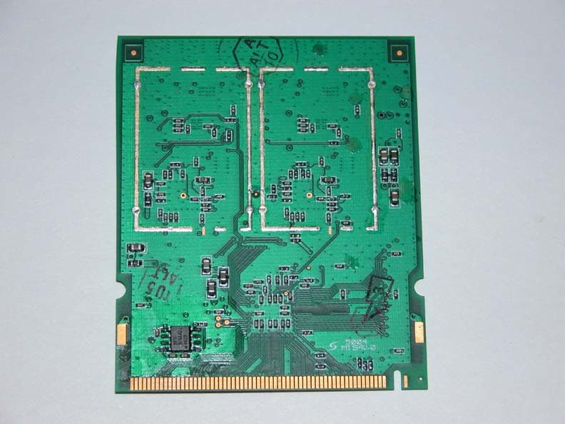
Click to zoom
Application Details
- Equipment Class
- DTS - Digital Transmission System
- Date of Grant
- Jan 04, 2005
- Application Purpose
- Original Equipment
- Date of Application
- Jan 04, 2005
- Equipment Note
- 802.11g WLAN Mini-PCI Module
- Frequency Range
- 2412.00000000 - 2462.00000000
- Company
- D-Link Corporation
- Country
- United States
Documents & Files
Document Text
Text extracted from the exhibit documents filed with the FCC. Open a document above to read the original.
Users Manual
2 DI-624M User’s Manual D-Link Systems, Inc. Table of Contents Table of Contents Package Contents ...............................................................................4 Minimum System Requirements ..............................................................4 Introduction ......................................................................................5 Features and Benefits ..........................................................................6 Hardware Overview .............................................................................7 Connections .........................................................................................................7 LEDs .....................................................................................................................8 Wireless Basics .................................................................................9 Standards-Based Technology .............................................................................10 Installation Considerations .................................................................................10 Getting Started ..................................................................................11 Using the Configuration Menu ................................................................12 Home .................................................................................................................13 Wizard ..........................................................................................................13 Wireless ........................................................................................................14 WAN .............................................................................................................15 Dynamic IP Address ................................................................................15 Static IP Address .....................................................................................16 PPPoE .....................................................................................................18 LAN ...............................................................................................................20 DHCP ............................................................................................................21 Advanced ...........................................................................................................22 Virtual Server ................................................................................................22 Applications ..................................................................................................24 Filters ............................................................................................................26 IP Filters ..................................................................................................26 MAC Filters ..............................................................................................27 Parental Control ............................................................................................28 URL Blocking ..........................................................................................28 Domain Blocking .....................................................................................29 Firewall .........................................................................................................30 DMZ ..............................................................................................................31 Performance .................................................................................................32 Tools ..................................................................................................................34 Admin ...........................................................................................................34 Time ..............................................................................................................36 3 DI-624M User’s Manual D-Link Systems, Inc. Table of Contents System .........................................................................................................37 Firmware .......................................................................................................38 Misc. .............................................................................................................39 Tools ..................................................................................................................41 Device Info ....................................................................................................41 Log ...............................................................................................................43 Log Settings ............................................................................................44 Stats .............................................................................................................45 Wireless ........................................................................................................45 Networking Basics .............................................................................46 Naming Your Computer ......................................................................................53 Checking the IP Address in Windows XP ...........................................................54 Assigning a Static IP Address in Windows XP/2000 ..........................................56 Assigning a Static IP Address in Macintosh OSX ...............................................58 Checking the Wireless Connection by Pinging in Windows XP and 2000 ...........61 Checking the Wireless Connection by Pinging in Windows Me and 98 ..............62 Troubleshooting ................................................................................63 Technical Specifications ...............................................…
Text truncated - open the document above for the full version.
Users Manual
91 DI-624M User’s Manual D-Link Systems, Inc. Frequently Asked Questions 8 How do I open a range of ports on my DI-624M using Firewall rules? Step 1: Access the router’s Web configuration by entering the router’s IP Address in your Web browser. The default IP Address is 192.168.0.1. Login using your password. The default username is “admin” and the password is blank. If you are having difficulty accessing Web management, please see the first question in this section. Step 2: From the Web management Home page, click the Advanced tab then click the Firewall button. Step 3: Click on Enabled and type in a name for the new rule. Step 4: Choose WAN as the Source and enter a range of IP Addresses out on the internet that you would like this rule applied to. If you would like this rule to allow all internet users to be able to access these ports, then put an Asterisk in the first box and leave the second box empty. Step 5: Select LAN as the Destination and enter the IP Address of the computer on your local network that you want to allow the incoming service to. This will not work with a range of IP Addresses. 92 DI-624M User’s Manual D-Link Systems, Inc. Frequently Asked Questions Step 6: Enter the port or range of ports that are required to be open for the incoming service. Step 7: Click Apply and then click Continue. Note: Make sure DMZ host is disabled. Because our routers use NAT (Network Address Translation), you can only open a specific port to one computer at a time. For example: If you have 2 web servers on your network, you cannot open port 80 to both computers. You will need to configure 1 of the web servers to use port 81. Now you can open port 80 to the first computer and then open port 81 to the other computer. 9 What are virtual servers? A Virtual Server is defined as a service port, and all requests to this port will be redirected to the computer specified by the server IP. For example, if you have an FTP Server (port 21) at 192.168.0.5, a Web server (port 80) at 192.168.0.6, and a VPN server at 192.168.0.7, then you need to specify the following virtual server mapping table: 10 How do I use PC Anywhere with my DI-624M router? You will need to open 3 ports in the Virtual Server section of your D-Link router. Step 1: Open your web browser and enter the IP Address of the router (192.168.0.1). Server Port Server IP Enable 21 192.168.0.5 X 80 192.168.0.6 X 1723 192.168.0.7 X 93 DI-624M User’s Manual D-Link Systems, Inc. Frequently Asked Questions Step 3: Enter the information as seen below. The Private IP is the IP Address of the computer on your local network that you want to connect to. Step 4: The first entry will read as shown above. Step 5: Click Apply and then click Continue. Step 6: Create a second entry as shown below: 94 DI-624M User’s Manual D-Link Systems, Inc. Frequently Asked Questions Step 7: Click Apply and then click Continue. Step 8: Create a third and final entry as shown below: Step 9: Click Apply and then click Continue. Step 10: Run PCAnywhere from the remote site and use the WAN IP Address of the router, not your computer ́s IP Address. 11 How can I use eDonkey behind my D-Link Router? You must open ports on your router to allow incoming traffic while using eDonkey. eDonkey uses three ports (4 if using CLI): 4661 (TCP) To connect with a server 4662 (TCP) To connect with other clients 4665 (UDP) To communicate with servers other than the one you are connected to. 4663 (TCP) *Used with the command line (CLI) client when it is configured to allow remote connections. This is the case when using a Graphical Interface (such as the Java Interface) with the client. Step 1: Open your web browser and enter the IP Address of your router (192.168.0.1). Enter username (admin) and your password (leave blank). 95 DI-624M User’s Manual D-Link Systems, Inc. Frequently Asked Questions Step 2: Click on Advanced and then click Firewall. Step 3: Create a new firewall rule: Click Enabled. Enter a name (edonkey). Click Allow. Next to Source, select WAN under interface. In the first box, enter an *. Leave the second box empty. Next to Destination, select LAN under interface. Enter the IP Address of the computer you are running eDonkey from. Leave the second box empty. Under Protocol, select *. In the port range boxes, enter 4661 in the first box and then 4665 in the second box. Click Always or set a schedule. Step 4: Click Apply and then Continue. 12 How do I set up my router for SOCOM on my Playstation 2? To allow you to play SOCOM and hear audio, you must download the latest firmware for the router (if needed), enable Game Mode, and open port 6869 to the IP Address of your Playstation. Step 1: Upgrade firmware (follow link above). 96 DI-624M User’s Manual D-Link Systems, Inc. Frequently Asked Questions Step 2: Open your web browser and enter the IP Address of the router (192.168.0.1). Enter username (admin) and your password (blank by default). Step 3: Click on the Advanced tab and then click on Virtual Server on the left side. Step 4: You will now create a new Virtual Server entry. Click Enabled and enter a name (socom). Enter the IP Address of your Playstation for Private IP. Step 5: For Protocol Type select Both. Enter 6869 for both the Private Port and Public Port. Click Always. Click Apply to save changes and then Continue. Step 6: Click on the Tools tab and then Misc on the left side. Step 7: Make sure Gaming Mode is Enabled. If not, click Enabled. Click Apply and then Continue. 13 How can I use Gamespy behind my D-Link router? Step 1: Open your web browser and enter the IP Address of the router (192.168.0.1). Enter admin for the username and your password (blank by default). socom 192.168.0.100 Both 6869 6869 97 DI-624M User’s Manual D-Link Systems, Inc. Frequently Asked Questions Step 3: You will create 2 entries. Step 4: Click Enabled and enter Settings: NAME - Gamespy1 PRIVATE IP - The IP Address of your computer that you are running Gamespy from. PROTOCOL TYPE - Both PRIVAT…
Text truncated - open the document above for the full version.
Cover Letter(s)
The test proposal with the dipole antennas is acceptable with either of the following optional modular approval restrictions. However, in addition we require that additional prescan testing must be made to ensure that the dipole antennas are rotated and folded as described in the addendum to ensure that the worst case is tested. 1) The module is approved for use as long as the same dipole antennas, or dipole antennas with identical properties, are used. However, the dipole antennas may be placed with different relative spacing to each other. 2) The module is approved for use as long as the same dipole antennas, or dipole antennas with identical properties are used, AND the relative antenna spacings must be maintained exactly as in the measurement case that was used for regulatory approval. We want additional testing with regard to the PCB antennas. We need more information on how the OEM will construct and install these antennas. What would be the highest gain of the PCB antenna? What instructions are given to the OEM to construct and install these antennas? How do you ensure that the installation of the PCB antenna at different locations on the motherboard will comply with spurious emissions? We are concerned that spurious emissions with different PCB antenna layouts and installations will not comply with the technical requirements. If only the PCB antennas as shown in the attached document are used, tested and OEM installed as shown, then the following is applicable for the PCB antennas. A) The module is approved for use as long as the same PCB antennas are used and installed AND the relative antenna spacing is maintained exactly as in the measurement case that was used for regulatory approval If you want more flexibility for PCB antennas, additional testing and information is needed. For example, testing will have to be submitted to ensure that varying the construction(length, thickness and shape), installation (spacing and location) of the PCB antennas will not affect the emissions. The position/location of the PCB antennas relative to ground plane(s) and other PCB components such as oscillators or high frequency components need to be addressed. A TCB can authorize this device with the dipole antennas as long as the filing is for mobile exposure conditions. The device uses a simple array antenna design with no new technology issues. The array consists of two low gain antennas with a total antenna gain of less than 6 dBi. The test proposal for determining the total output power and total antenna gain agrees with methods we have allowed for phased array systems. Due to approval as a mobile device, no SAR issues are involved. As indicated, additional information is needed for approval of the PCB antennas. A copy of this letter and both the original proposal with addendum(attached) must be submitted in the TCB filing. Further guidance prior to TCB approval will be required for any changes to the device(antenna, RF circuitry etc...). Because the proposal does not indicate the developer/manufacturer, the TCB must inform the FCC when this device is filed.
Cover Letter(s)
Company: D-Link Corporation FCC ID: KA2DI624MA1 Request for transmitter modular approval Transmitter Module Characteristics Item Requirements EUT 1 Have its own RF shielding Device is equipped with Metal shielding to cover RF section. Refer to external photos 2 Have buffered modulation/data inputs (if such inputs are provided), All inputs to the modules are buffered through logic or microprocessor inputs. 3 Have it own power supply regulation Two on-board low dropout regulators provide 2.5V and 1.8V provide regulated supplies 4 Meet the antenna requirements of Section 15.203 Device is equipped with unique antenna (u.FL(v)- LP-040) connector. Refer to external photos 5 Be tested in a stand-alone configuration, i.e., the antenna, AC or DC power and data input/output lines must be connected to the module but, the module must not be inside another case during testing Device was tested stand- alone, using a laptop w/ extender card for host control. Refer to setup photos. 6 Be labeled with its own FCC ID number, and if the FCC ID is not visible when the module is installed inside another device, then the outside of the device into which the module is installed must also display a label referring to the enclosed module. FCC ID: KA2DI624MA1 Module will be installed inside the D-Link DI624M AccessPoint platform. The DI624M will have a label stating that the product contains KA2DI624MA1. 7 The modular transmitter is manufactured so that the user cannot influence the operation of the transmitter that will operate outside of the scope of the regulations. Refer to “User’s Guide” Exhibit 8 Address compliance with the Commission's RF exposure limits in Sections 1.1310 and 2.1093. In addition, spread spectrum transmitters operating under Section 15.247 are required to address RF exposure compliance in accordance with Section 15.247(b)(4). 20cm distance will be maintained between the user and the product. No SAR testing was required.
ID Label/Location Info
PROPOSED FCC ID LABEL AND LOCATION D-LINK CORPORATION This device complies with Part 15 of the FCC Rules. Operation is subject to the following two conditions: (1) this device may not cause harmful interference, and (2) this device must accept any interference received, including interference that may cause undesired operation. FCC ID: KA2DI624MA1 FCC ID LABEL LOCATION PROPOSED FCC ID LABEL FOR HOST DEVICE D-LINK CORPORATION This device contains FCC ID: KA2DI624MA1
Test Report
FCC CFR47 PART 15 SUBPART C CERTIFICATION TEST REPORT FOR 802.11g Wireless Network Mini PCI MODEL NUMBER: WL MP 2554 36A0 B10 FCC ID: KA2DI624MA1 REPORT NUMBER: 04U3115-1, Revision B ISSUE DATE: DECEMBER 29, 2004 Prepared for D-LINK CORPORATION 2F, NO 233-2, PAO-CHIAO ROAD HSIN-TIEN, TAIPEI, TAIWAN ROC Prepared by COMPLIANCE ENGINEERING SERVICES, INC. d.b.a. COMPLIANCE CERTIFICATION SERVICES 561F MONTEREY ROAD, MORGAN HILL, CA 95037, USA TEL: (408) 463-0885 FAX: (408) 463-0888 REPORT NO: 04U3115-1, Rev. B DATE: DECEMBER 29, 2004 EUT: 802.11g Wireless Network Mini PCI FCC ID: KA2DI624MA1 Page 2 of 215 COMPLIANCE CERTIFICATION SERVICES DOCUMENT NO: CCSUP4031A 561F MONTEREY ROAD, MORGAN HILL, CA 95037 USA TEL: (408) 463-0885 FAX: (408) 463-0888 This report shall not be reproduced except in full, without the written approval of CCS. Revision History Rev. Revisions Revised By B Changed FCC ID number, revised MPE Calculations MH REPORT NO: 04U3115-1, Rev. B DATE: DECEMBER 29, 2004 EUT: 802.11g Wireless Network Mini PCI FCC ID: KA2DI624MA1 Page 3 of 215 COMPLIANCE CERTIFICATION SERVICES DOCUMENT NO: CCSUP4031A 561F MONTEREY ROAD, MORGAN HILL, CA 95037 USA TEL: (408) 463-0885 FAX: (408) 463-0888 This report shall not be reproduced except in full, without the written approval of CCS. TABLE OF CONTENTS 1. ATTESTATION OF TEST RESULTS............................................................................................. 5 2. TEST METHODOLOGY .................................................................................................................. 6 3. FACILITIES AND ACCREDITATION .......................................................................................... 6 4. CALIBRATION AND UNCERTAINTY.......................................................................................... 6 4.1. MEASURING INSTRUMENT CALIBRATION ............................................................................. 6 4.2. MEASUREMENT UNCERTAINTY ............................................................................................... 6 5. EQUIPMENT UNDER TEST............................................................................................................7 5.1. DESCRIPTION OF EUT ..............................................................................................................7 5.2. MAXIMUM OUTPUT POWER .................................................................................................... 7 5.3. DESCRIPTION OF AVAILABLE ANTENNAS ............................................................................. 8 5.4. SOFTWARE AND FIRMWARE .................................................................................................... 8 5.5. WORST-CASE CONFIGURATION AND MODE......................................................................... 9 5.6. DESCRIPTION OF TEST SETUP .............................................................................................. 10 6. TEST AND MEASUREMENT EQUIPMENT .............................................................................. 12 7. LIMITS AND RESULTS ................................................................................................................. 13 7.1. CHANNEL TESTS FOR THE 2400 TO 2483.5 MHz BAND, SINGLE CHAIN .......................... 13 7.1.1. 6 dB BANDWIDTH ........................................................................................................... 13 7.1.2. 99% BANDWIDTH............................................................................................................ 22 7.1.3. PEAK OUTPUT POWER .................................................................................................. 37 7.1.4. MAXIMUM PERMISSIBLE EXPOSURE ........................................................................ 52 7.1.5. AVERAGE POWER........................................................................................................... 55 7.1.6. PEAK POWER SPECTRAL DENSITY ............................................................................ 57 7.1.7. CONDUCTED SPURIOUS EMISSIONS.......................................................................... 66 7.2. CHANNEL TESTS FOR THE 2400 TO 2483.5 MHz BAND, DUAL CHAIN ............................. 81 7.2.1. 6 dB BANDWIDTH ........................................................................................................... 81 7.2.2. 99% BANDWIDTH............................................................................................................ 91 7.2.3. PEAK OUTPUT POWER ................................................................................................ 112 7.2.4. MAXIMUM PERMISSIBLE EXPOSURE ...................................................................... 134 7.2.5. AVERAGE POWER......................................................................................................... 137 7.2.6. PEAK POWER SPECTRAL DENSITY .......................................................................... 138 7.2.7. CONDUCTED SPURIOUS EMISSIONS........................................................................ 148 7.3. RADIATED EMISSIONS........................................................................................................... 165 7.3.1. TRANSMITTER RADIATED SPURIOUS EMISSIONS ............................................... 165 7.3.2. TRANSMITTER ABOVE 1 GHz FOR 2400 TO 2483.5 MHz BAND, b MODE .......... 168 7.3.3. TRANSMITTER ABOVE 1 GHz FOR 2400 TO 2483.5 MHz BAND, g MODE, SINGLE CHAIN 177 7.3.4. TRANSMITTER ABOVE 1 GHz FOR 2400 TO 2483.5 MHz BAND, g MODE, DUAL CHAIN 187 7.3.5. WORST-CASE RADIATED EMISSIONS BELOW 1 GHz ........................................... 201 REPORT NO: 04U3115-1, Rev. B DATE: DECEMBER 29, 2004 EUT: 802.11g Wireless Network Mini PCI FCC ID: KA2DI624MA1 Page 4 of 215 COMPLIANCE CERTIFICATION SERVICES DOCUMENT NO: CCSUP4031A 561F MONTEREY ROAD, MORGAN HILL, CA 95037 USA TEL: (408) 463-0885 FAX: (408) 463-0888 This report shall not …
Text truncated - open the document above for the full version.
Test Setup Photos
REPORT NO: 04U3115-1, Rev. B DATE: DECEMBER 29, 2004 EUT: 802.11g Wireless Network Mini PCI FCC ID: KA2DI624MA1 Page 211 of 215 COMPLIANCE CERTIFICATION SERVICES DOCUMENT NO: CCSUP4031A 561F MONTEREY ROAD, MORGAN HILL, CA 95037 USA TEL: (408) 463-0885 FAX: (408) 463-0888 This report shall not be reproduced except in full, without the written approval of CCS. 8. SETUP PHOTOS ANTENNA PORT CONDUCTED RF MEASUREMENT SETUP ANTENNA PORT CONDUCTED PHOTO REPORT NO: 04U3115-1, Rev. B DATE: DECEMBER 29, 2004 EUT: 802.11g Wireless Network Mini PCI FCC ID: KA2DI624MA1 Page 212 of 215 COMPLIANCE CERTIFICATION SERVICES DOCUMENT NO: CCSUP4031A 561F MONTEREY ROAD, MORGAN HILL, CA 95037 USA TEL: (408) 463-0885 FAX: (408) 463-0888 This report shall not be reproduced except in full, without the written approval of CCS. RADIATED RF MEASUREMENT SETUP RADIATED FRONT PHOTO REPORT NO: 04U3115-1, Rev. B DATE: DECEMBER 29, 2004 EUT: 802.11g Wireless Network Mini PCI FCC ID: KA2DI624MA1 Page 213 of 215 COMPLIANCE CERTIFICATION SERVICES DOCUMENT NO: CCSUP4031A 561F MONTEREY ROAD, MORGAN HILL, CA 95037 USA TEL: (408) 463-0885 FAX: (408) 463-0888 This report shall not be reproduced except in full, without the written approval of CCS. RADIATED BACK PHOTO REPORT NO: 04U3115-1, Rev. B DATE: DECEMBER 29, 2004 EUT: 802.11g Wireless Network Mini PCI FCC ID: KA2DI624MA1 Page 214 of 215 COMPLIANCE CERTIFICATION SERVICES DOCUMENT NO: CCSUP4031A 561F MONTEREY ROAD, MORGAN HILL, CA 95037 USA TEL: (408) 463-0885 FAX: (408) 463-0888 This report shall not be reproduced except in full, without the written approval of CCS. POWERLINE CONDUCTED EMISSIONS MEASUREMENT SETUP LINE CONDUCTED FRONT PHOTO REPORT NO: 04U3115-1, Rev. B DATE: DECEMBER 29, 2004 EUT: 802.11g Wireless Network Mini PCI FCC ID: KA2DI624MA1 Page 215 of 215 COMPLIANCE CERTIFICATION SERVICES DOCUMENT NO: CCSUP4031A 561F MONTEREY ROAD, MORGAN HILL, CA 95037 USA TEL: (408) 463-0885 FAX: (408) 463-0888 This report shall not be reproduced except in full, without the written approval of CCS. END OF REPORT LINE CONDUCTED BACK PHOTO
Contact Information
Applicant
Brett Adair(General Counsel)
Test Firm
Compliance Certification Services IncSteve Cheng
Technical Specifications
| # | Rule Parts | Frequency Range | Power Output |
|---|---|---|---|
| 1 | 15C | 2.41 GHz - 2.46 GHz | 762.00 mW |
Other Applications from D-Link Corporation

KA2CS6012A1
Jul 07, 20262K Fixed Indoor Cloud Camera, 2K Fixed Indoor Wi-Fi Camera
Equipment Class
DTS - Digital Transmission SystemKA2AE65UA1
Mar 02, 2026Wi-Fi 7 BE6500 USB 3.0 Dongle
Equipment Class
NII - Unlicensed National Information Infrastructure TXKA2APE9560A1
Nov 17, 2025BE9500 Celling mount Access Point
Equipment Class
6ID - 15E 6 GHz Low Power Indoor Access PointKA2AX9UA1
Dec 04, 2024AX900 Wi-Fi 6 USB Adapter, Wi-Fi 6 AX900 USB 2.0 Dongle
Equipment Class
DSS - Part 15 Spread Spectrum TransmitterKA2AC13UA1
Dec 04, 2024AC1300 Wi-Fi 5 USB Adapter, Wi-Fi 5 AC1300 USB 2.0 Dongle
Equipment Class
DTS - Digital Transmission System