KA2DI714PPLUSWireless Router
D-Link Corporation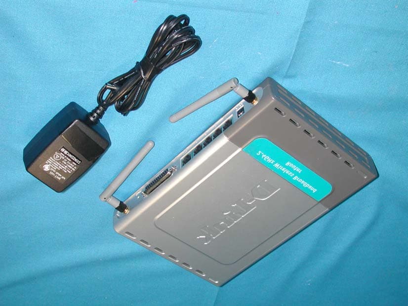
Click to zoom
Application Details
- Equipment Class
- DSS - Part 15 Spread Spectrum Transmitter
- Date of Grant
- Jan 16, 2003
- Application Purpose
- Original Equipment
- Date of Application
- Jan 16, 2003
- Equipment Note
- Wireless Router
- Frequency Range
- 2412.00000000 - 2462.00000000
- Company
- D-Link Corporation
- Country
- United States
Documents & Files
Document Text
Text extracted from the exhibit documents filed with the FCC. Open a document above to read the original.
Users Manual
Enhanced 2.4 GHz Manual Building Networks for People Wireless Router AirPlus DI-714P+ D-LINK 2 Contents Package Contents................................................................................ 3 Introduction............................................................................................ 4 Wireless Basics .................................................................................... 6 Getting Started...................................................................................... 9 Using the Configuration Menu.............................................................. 11 Networking Basics.............................................................................. 43 Troubleshooting................................................................................... 72 Technical Specifications...................................................................... 78 Contacting Technical Support.............................................................. 81 Warranty and Registration................................................................... 82 Installing the Print Server Software...................................................... 39 Configuring the Print Server Software.................................................. 41 3 Contents of Package: D-Link AirPlus DI-714P+ 2.4GHz Wireless Router Power Adapter ñ 5V DC Manual on CD Quick Installation Guide Package Contents Note: Using a power supply with a different voltage rating than the one included with the DI-714P+ will cause damage and void the warranty for this product. If any of the above items are missing, please contact your reseller. System Requirements For Configuration: ! ! ! ! Computer with Windows, Macintosh, or Linux-based operating system with an installed Ethernet adapter ! Internet Explorer version 5.5 or Netscape Navigator version 4.79 and above, with JavaScript enabled ! Ethernet-Based Cable or DSL Modem ! 4 Introduction The D-Link AirPlus DI-714P+ Wireless Broadband Router is an enhanced 802.11b high-performance, wireless router with a printer port. It is an ideal way to extend the reach and number of computers connected to your wireless network. Unlike most 802.11b routers, the DI-714P+ is capable of data transfer speeds up to 22 Mbps (compared to the standard 11 Mbps) when used with other D- Link AirPlus products such as the DWL-520+ and DWL-650+ Wireless Adapters. After completing the steps outlined in the Quick Installation Guide (included in your package) you will have the ability to share information and resources, as well as share a printer wirelessly on your network. The DI-714P+ is compatible with most popular operating systems, including Macintosh, Linux and Windows, and can be integrated into a large network. This Manual is designed to help you connect the Router and D-Link AirPlus 2.4GHz Wireless Adapters into a network in Infrastructure mode. Please take a look at the Getting Started section in this manual to see an example of an Infrastructure network using the DI-714P+. 5 Connections DHCP server support enables all networked computers to automatically receive IP addresses Wireless connection of up to 22Mbps Web-based interface for Management Access Control to manage users on the network Maximum reliability, throughput and connectivity with automatic data rate switching Stronger network security with 256-bit encryption Printer port enables connection to a network printer Receptor for the Power Adapter WAN port is the connection for the Ethernet cable to the Cable or DSL modem Pressing the Reset Button restores the router to its original factory default settings. Printer Port. Most printers will work with this bi-directional printer port. If you experience difficulties with a multi- functional printer, please confirm that your printer is compatible with a bi- directional port. LAN ports provide connections to Ethernet- enabled devices. Connects multiple computers to an Ethernet Broadband (Cable or DSL) modem to share the Internet connection ! Supports VPN pass-through, providing added security ! Advanced Firewall features for added network security ! Features & Benefits ! ! ! ! ! ! ! Note: Please refer to the Troubleshooting section in this manual for instructions on how to use the Reset button WAN and LAN ports auto detect cable types (straight-through or cross-over) ! UPnP supported ! All ports (both LAN and WAN) auto-sense cable types to accomodate straight-through or cross-over cable. 6 LEDS LED stands for Light-Emitting Diode. The DI-714P+ has the following LEDs as described below: LED LED Activity Power A steady light indicates a connection to a power source M1 LED M2 LED Lights up when the device has an Internet Connection WAN A solid light indicates connection on the WAN port. This LED blinks during data transmission WLAN A solid light indicates that the wireless segment is ready. This LED blinks during wireless data transmission. D-Link AirPlus wireless products are based on industry standards to provide easy-to- use and compatible high-speed wireless connectivity within your home, business or public access wireless networks. Strictly adhering to the IEEE standard, the D-Link AirPlus wireless family of products will allow you to securely access the data you want, when and where you want it. You will be able to enjoy the freedom that wireless networking delivers. A wireless local area network (WLAN) is a cellular computer network that transmits and receives data with radio signals instead of wires. Wireless LANs are used increasingly in both home and office environments, and public areas such as airports, coffee shops and universities. Innovative ways to utilize WLAN technology are helping people to work and communicate more efficiently. Increased mobility and the absence of cabling and other fixed infrastructure have proven to be beneficial for many users. Wireless Basics Flashes once per second to indicate an active system LOCAL NETWORK (Ports 1-4) A solid l…
Text truncated - open the document above for the full version.
Users Manual
38 Using the Configuration Menu Status > Log Status > Log Settings This log page displays logs of activities and events that are occuring through the DI-714P+ Enter in the IP address of a syslog server within the network. Click Enable to activiate the policy. The DI-714P+ will send all of itís logs to the specified syslog server. Syslog Server- E-Mail Alert- The DI-714P+ can be set up to send the log files to a specific email address. SMTP Server IP- Enter in the IP address of the mail server. Send E-Mail alert to- Enter in the email address of the recipient who will receive the email log. E-Mail Subject- Enter in the email subject. Click on Send Mail Now to send the email log. 39 Using the Configuration Menu Status > Stats This screen displays the Receive and Transmit packets passing through the DI-714P+. Click on Refresh for the most recent information and Reset to clear the counter. Status > Wireless This screen displays the connection time and the MAC Address of the connected wire- less clients. Click on Refresh for the most recent information.. 40 Using the Configuration Menu Help This screen displays the complete Help menu. For help at anytime, click the Help tab in the Configuration menu. Insert the installation CD-ROM into the CD-ROM drive. The following window will be shown automatically. If it is not, please run ìautorun.exeî on the CD- ROM. Installing the Print Server Software Select your Windows operating system Click Install Windows Printer Software 41 Wait until the following Welcome dialog appears. Select the destination folder. Click Next After rebooting your computer, the software installation procedure is finished. Installing the Print Server Software (continued) Click OK Then, the setup program will begin to install the programs into the destination folder. When the following window is displayed. Click Finish Click Next 42 Configuring on Windows 98se/Me Platforms After you finish the software installation procedure, your computer will be capable of network printing provided by the DI- 714P+. For convenience, we call the printer connected to the printer port of the DI-714P+ a printer server. On a Windows 95/98 platform, open the Printers window in the My Computer menu. Now, you can configure the print server of the DI-714P+: Find out the corresponding icon of your printer server, for example, the HP LaserJet 6L. Right click on that icon, and then select Properties. The following screen appears: Choose the ìPRTmate: (All-in-1)î from the list attached at the Print To item. Be sure that the Printer Driver item is configured to the correct driver of your printer server. Type in the IP address of the DI-714P+. Click on the Details tab Click Port Settings Click OK 43 Configuring on Windows 2000/XP Platforms The configuration procedure for a Windows 2000/XP platform is similar to that of Windows 95/98 except the screen of printer Properties: (Note: Screen shots are taken in Windows 2000, similar screens will appear in Windows XP.) Click Port Click Configure Port Type in the IP address of the DI-714P+. Click OK 44 Using the Network Setup Wizard in Windows XP In this section you will learn how to establish a network at home or work, using Microsoft Windows XP. Note: Please refer to websites such as http://www.homenethelp.com and http://www.microsoft.com/windows2000 for information about networking computers using Windows 2000, ME or 98. Go to Start>Control Panel>Network Connections Select Set up a home or small office network Networking Basics When this screen appears, Click Next. 45 Please follow all the instructions in this window: Networking Basics Click Next In the following window, select the best description of your computer. If your computer connects to the internet through a gateway/router, select the second option as shown. Click Next 46 Enter a Computer description and a Computer name (optional.) Networking Basics Click Next Enter a Workgroup name. All computers on your network should have the same Workgroup name. Click Next 47 Please wait while the Network Setup Wizard applies the changes. Networking Basics When the changes are complete, click Next. Please wait while the Network Setup Wizard configures the computer. This may take a few minutes. 48 Networking Basics In the window below, select the option that fits your needs. In this example, Create a Network Setup Disk has been selected. You will run this disk on each of the computers on your network. Click Next. Insert a disk into the Floppy Disk Drive, in this case drive A. 49 Networking Basics Please read the information under Hereís how in the screen below. After you complete the Network Setup Wizard you will use the Network Setup Disk to run the Network Setup Wizard once on each of the computers on your network. To continue click Next. 50 Networking Basics Please read the information on this screen, then click Finish to complete the Network Setup Wizard. The new settings will take effect when you restart the computer. Click Yes to restart the computer. You have completed configuring this computer. Next, you will need to run the Network Setup Disk on all the other computers on your network. After run- ning the Network Setup Disk on all your computers, your new wireless net- work will be ready to use. 51 ! Networking Basics Naming your Computer To name your computer, please follow these directions:In Windows XP: Click Start (in the lower left corner of the screen) Right-click on My Computer Select Properties and click ! ! ! ! ! Select the Computer Name Tab in the System Properties window. You may enter a Com- puter Description if you wish; this field is optional. To rename the computer and join a domain, Click Change. 52 Networking Basics Naming your Computer ! In this window, enter the Computer name Select Workgroup and enter the name of the Workgroup All computers on your network must have the same Workgroup name. Click OK ! ! ! Checking the IP Address in Windows XP The wireless adapter-equipped computers in your…
Text truncated - open the document above for the full version.
Users Manual
61 Networking Basics Adding a local printer Click Next Select Local printer attached to this computer (Deselect Automati- cally detect and install my Plug and Play printer if it has been selected.) Click Next Select Use the follow- ing port: From the pull-down menu select the correct port for your printer (Most computers use the LPT1: port, as shown in the illustration.) Click Next ! ! ! ! ! ! ! 62 Networking Basics Adding a local printer Select and highlight the correct driver for your printer. Click Next (If the correct driver is not displayed, insert the CD or floppy disk that came with your printer and click Have Disk.) At this screen, you can change the name of the printer (optional.) Click Next Select Yes, to print a test page. A successful printing will confirm that you have chosen the correct driver. Click Next ! ! ! ! ! ! 63 Networking Basics Adding a local printer This screen gives you information about your printer. Click Finish When the test page has printed, Click OK 64 Networking Basics Adding a local printer Go to Start> Printers and Faxes A successful installation will display the printer icon as shown at right. You have successfully added a local printer. Sharing a network printer After you have run the Network Setup Wizard on all the computers on your network, you can run the Add Printer Wizard on all the computers on your network. Please follow these directions to use the Add Printer Wizard to share a printer on your network: Go to Start> Printers and Faxes ! ! 65 Networking Basics Sharing a network printer Click on Add a printer Click Next Select Network Printer Click Next ! ! ! ! 66 Networking Basics Sharing a network printer Select Browse for a printer Click Next Select the printer you would like to share Click Next Click Finish ! ! ! ! 67 Networking Basics Sharing a network printer To check for proper installation: Go to Start > Printers and Faxes The printer icon will appear at right, indicating proper installation. You have completed adding the printer. To share this printer on your network: Remember the printer name Run the Add Printer Wizard on all the computers on your network Make sure you have already run the Network Setup Wizard on all the network computers After you run the Add Printer Wizard on all the computers in the network, you can share the printer. ! ! ! ! ! 68 Networking Basics Sharing an LPR printer To share an LPR printer (using a print server,) you will need a Print Server such as the DP-101P+. Please make sure that you have run the Network Setup Wizard on all the computers on your network. To share an LPR printer, please follow these directions: Go to Start > Printers and Faxes Click on Add a Printer The screen to the right will appear Click Next Select Local Printer... Click Next ! ! ! ! ! 69 Networking Basics Sharing an LPR printer Select Create a new port From the pull-down menu, select Standard TCP/IP Port, as shown. Click Next Please read the instructions on this screen Click Next Enter the Printer IP Address and the Port Name, as shown. Click Next ! ! ! ! ! ! ! 70 Networking Basics Sharing an LPR printer In this screen, select Custom Click Settings Enter the Port Name and the Printer Name or IP Address. Select LPR Enter a Queue Name (if your Print-Server/ Gateway has more than one port, you will need a Queue name.) Click OK ! ! ! ! ! ! 71 Networking Basics Sharing an LPR printer Click Next Select Keep existing driver If the printer driver is already installed, do the following: Click Have Disk Insert the printer driver disk that came with your printer. Select the printer you are adding from the list of Printers. Click Finish This screen will show you information about your printer. ! ! ! ! ! ! ! 72 Networking Basics Sharing an LPR printer Note: You must run the Network Setup Wizard on all the computers on your network before you run the Add Printer Wizard. Please run the Add Printer Wizard on all the computers on your network in order to share the printer. Click Finish to complete the addition of the printer. This screen will display information about your printer. Click Next Select Yes, to print a test page. Click Next Please remember the name of your printer. You will need this information when you use the Add Printer Wizard on the other computers on your network. You can rename your printer if you choose. It is optional. ! ! ! ! ! ! ! 73 1.The computer used to configure the DI-714P+ cannot access the Configuration menu. Check that the Ethernet LED on the DI-714P+ is ON. If the LED is not ON, check that the cable for the Ethernet connection is securely inserted. Check that the Ethernet Adapter is working properly. Please see item 3 (Check that the drivers for the network adapters are installed properly) in this Troubleshooting section to check that the drivers are loaded properly. Check that the IP Address is in the same range and subnet as the DI-714P+. Please see Checking the IP Address in Windows XP in the Networking Basics section of this manual. Note: The IP Address of the DI-714P+ is 192.168.0.1. All the computers on the network must have a unique IP Address in the same range, e.g., 192.168.0.x. Any computers that have identical IP Addresses will not be visible on the network. They must all have the same subnet mask, e.g., 255.255.255.0 Do a Ping test to make sure that the DI-714P+ is responding. Go to Start>Run>Type Command>Type ping 192.168.0.1. A successful ping will show four replies. Troubleshooting This Chapter provides solutions to problems that can occur during the installation and operation of the DI-714P+ Wireless Broadband Router. We cover various aspects of the network setup, including the network adapters. Please read the following if you are having problems. Note: If you have changed the default IP Address, make sure to ping the correct IP Ad- dress assigned to the DI-714P+. Note: It is recommended that you use an Ethernet connection to configure the DI-714P+ Wireless Broadband Router. ! ! ! ! 74 2. The wireless clie…
Text truncated - open the document above for the full version.
Block Diagram
CPU SDRAM Flash ROM 5 Ports Switch Controller 802.11b+ Wireless Card Printer Buffer MII MII PrinterPort WAN Port 4 * LAN Ports RJ45 RJ45X4 ANT DB25 Connector DI-714P + System Block Diagram of Wireless Broadband Router 35.328Mhz OSC PCMCIA Glue Logic
External Photos
Report No.: 02CH012FI Page : 1 of 10 Version:1.0 Attachment 2 : EUT Detailed Photographs (1) EUT Photo (2) EUT Photo
ID Label/Location Info
CORPORATION FCC ID.: KA2DI714PPLUS 2F, No. 233-2, Pao-Chiao Road, Hsin-Tien, Taipei, Taiwan, R.O.C. Tel: 886 02 29161600 Fax: 886 02 29146299 LabelLoc The FCC ID and DoC Label will be placed on the equipment as shown in the photograph below. Wireless Router Model No.: DI-714P+ F F C C C C I I D D : : K K A A 2 2 D D I I 7 7 1 1 4 4 P P P P L L U U S S This device complies with Part 15 of the FCC Rules. Operation is subject to the following two conditions: (1) this device may not cause harmful interference and (2) this device must accept any interference received, including interference that may cause undesired operation. S/N: Made in Taiwan Wireless Router D-Link Model No.: DI-714P+ TESTED TO COMPLY WITH FCC STANDARDS FOR HOME OR OFFICE USE S/N: Made in Taiwan
ID Label/Location Info
CORPORATION FCC ID.: KA2DI714PPLUS 2F, No. 233-2, Pao-Chiao Road, Hsin-Tien, Taipei, Taiwan, R.O.C. Tel: 886 02 29161600 Fax: 886 02 29146299 LabelLoc The FCC ID and DoC Label will be placed on the equipment as shown in the photograph below. Wireless Router Model No.: DI-714P+ F F C C C C I I D D : : K K A A 2 2 D D I I 7 7 1 1 4 4 P P P P L L U U S S This device complies with Part 15 of the FCC Rules. Operation is subject to the following two conditions: (1) this device may not cause harmful interference and (2) this device must accept any interference received, including interference that may cause undesired operation. S/N: Made in Taiwan Wireless Router D-Link Model No.: DI-714P+ TESTED TO COMPLY WITH FCC STANDARDS FOR HOME OR OFFICE USE S/N: Made in Taiwan
Internal Photos
Report No.: 02CH012FI Page : 2 of 10 Version:1.0 (3) EUT Photo (4) EUT Photo Report No.: 02CH012FI Page : 3 of 10 Version:1.0 (5) EUT Photo Report No.: 02CH012FI Page : 4 of 10 Version:1.0 (6) EUT Photo Report No.: 02CH012FI Page : 5 of 10 Version:1.0 (7) EUT Photo Report No.: 02CH012FI Page : 6 of 10 Version:1.0 (8) EUT Photo (9) EUT Photo Report No.: 02CH012FI Page : 7 of 10 Version:1.0 (10) EUT Photo (11) EUT Photo Report No.: 02CH012FI Page : 8 of 10 Version:1.0 (12) EUT Photo (13) EUT Photo Report No.: 02CH012FI Page : 9 of 10 Version:1.0 (14) EUT Photo (15) EUT Photo Report No.: 02CH012FI Page : 10 of 10 Version:1.0 (16) EUT Photo
Operational Description
Report No. 02CH012FI Page: 6 of 50 Version:1.0 1.2. Operational Description EUT is a Wireless Router with 11 channels. This device provided four kind of transmitting speed 1,2,5.5 and 11Mbps. The device of RF carrier is DQPSK, DB PSK and CCK. The device adapts direct sequence spread spectrum modulation. The Connector antenna was provides diversity function to improve the receiving function. This Wireless Router is an IEEE 802.11b Wireless LAN adapter. It allows your computer to connect to a wireless network and to share resources, such as files or printers without being bound to the network wires. Operation in 2.4GHz Direst Sequence Spread Spectrum (DSSS) radio transmission, the Wireless Router transfers data at speeds up to 64/128-bit Wired Equivalent Protection (WEP) algorithm is used. In addition, its standard compliance ensures that it can communicate with any 802.11b network.
Schematics
55 44 33 22 11 D D C C B B A A OE#nWirelss HRD#HRDY# WAIT AteraGND WE# WLAN_IRQ# HAD19 35MHZB HRST OE#WE#IOWR#IORD# ATCKATMSATDI ATCK ATDIATMS ATDO AteraVCC ATDO HWR# $$$6 WLA19 CONFIG2 HAD16 HAD17WLA19HAD18HAD16 WLAN_CS# HWR# WLAN_CS# HRDY# OE# HAD19WAIT WE#nWirelss HRD# WLA19 HAD7HAD11 HC6 HC1HC3 HAD10 HAD10 HRST PCMCIA_VCC HAD0HAD11 HC4 HC4 HAD6HAD8 HAD18 HAD12 HC2 IORD# WAIT HC2HC6 HAD16 HAD12 Address_pulldown HC1 HAD1HAD7 HAD17WLA19 WLAN_IRQ# nWirelss HAD14 HC7 HAD0 WLAN_IRQ# HAD2 HC[1..7] WE#OE#IORD# HAD5 HC5 HAD13HAD15 WAIT HC5 HAD4HAD3HAD6 HAD3 HAD5 PA0 HC7 HAD[0..15] HAD15HAD13HAD9 PA0 HAD14 PCMCIA_VCC nWirelss HAD8HAD1 Address_pulldown IOWR# HC3 HAD2IOWR# HAD4HAD9 HRST 5,8 HRD# 2,5 HWR# 2,5 PWRGOOD 2,4,5 HRDY# 5 WLAN_CS# 5 35MHZB 5 HAD19 2,5 HRDY1# HAD[0..15] 2,5 WLAN_IRQ# 5 HAD16 2,5 HAD17 2,5 HC[1..7] 2,5 HAD18 2,5 WL_LED 3,5 +5V +3.3V PCMCIA_VCC +5V VCC VCC5 +5V PCMCIA_VCC +3.3V +3.3V +3.3V +3.3V +3.3V +3.3V +3.3V GND +3.3V R1690 R134 27 C128 0.01u R119220 R136 100k Q1 2N3904 1 23 R137 220 U5F74HC14 13 12 U5E 74HC14 11 10 R1354.7k R1594.7k R1460 R131 4.7k R1714.7k R1704.7k R172 0 U11 PCMCIA_CON2_1 1 17 34 16 35 51 68 42 18 33 52 3059 61 60 29 62 15 633143 9 57 28 36 44 6732 452758 2 26 3 25 4 24 5 23 6 22 64 12 65 11 66 8 37 10 38 21 39 13 40 14 41 2019464748495053545556 7 GND VCC GND IREG# GND VCC GND CE2 VPP IOIS16# VPP D0 WAIT REG INPACK A0 SPKR# WE/PGM STSCHG# D1 VS1 OE VS2 A1 CD1 IORD CD2 D2 IOWRA2RESET D3 A3 D4 A4 D5 A5 D6 A6 D7 A7 D8 A8 D9 A9 D10 A10 D11 A11 D12 A12 D13 A13 D14 A14 D15 A15A16A17A18A19A20A21A22A23A24A25CE1 R1450 C1360.1u C1430.1u C1320.1u R129 4.7k R150 4.7k U6 123456789 1011 12 13 14 15 16 17 18 19 20 21 22 3332313029282726252423 44 43 42 41 40 39 38 37 36 35 34 TDI/IO1IO2IO3GNDIO4IO5TMS/IO6IO7VCCIO8GND IO10 IO11 IO12 IO13 GND VCC IO14 IO15 IO16 IO17 IO18 IO27 TDO/IO26 IO25 GND VCC IO23IO22 TCK/IO21 IO20 GND IO19 IO32 IO31 IO30 VCC IN4/OE2/CLK2 IN3/Gclr IN2/OE1 IN1/CLK1 GND IO29 IO28 C1250.1u R148 0 U10 PCMCIA_CON2_1 1 17 34 16 35 51 68 42 18 33 52 3059 61 60 29 62 15 633143 9 57 28 36 44 6732 452758 2 26 3 25 4 24 5 23 6 22 64 12 65 11 66 8 37 10 38 21 39 13 40 14 41 2019464748495053545556 7 GND VCC GND IREG# GND VCC GND CE2 VPP IOIS16# VPP D0 WAIT REG INPACK A0 SPKR# WE/PGM STSCHG# D1 VS1 OE VS2 A1 CD1 IORD CD2 D2 IOWRA2RESET D3 A3 D4 A4 D5 A5 D6 A6 D7 A7 D8 A8 D9 A9 D10 A10 D11 A11 D12 A12 D13 A13 D14 A14 D15 A15A16A17A18A19A20A21A22A23A24A25CE1 C15247u R167 0 R144 0 R1424.7k R165 0 R163 0 R16810K C149 0.1u C15147u R177 4.7k C150 0.1u R16010K R178 4.7k R1470 R1514.7k R1520 J3 HEADER2X5 1 2 3 4 5 6 7 8 9 10 12345678910 R1320R1430 C1290.1u C133 0.1u 55 44 33 22 11 D D C C B B A A PTD0 CFG0CFG1CFG2CFG3CFG4CFG5CFG6CFG7 STB#INIT ACK#BUSYPESLCTERR# PTD1PTD2PTD3PTD4PTD5PTD6PTD7 GNDGNDGND STB# GND STRB GNDGNDGNDGNDGND PTD1PTD2PTD6PTD0PTD7PTD3PTD5PTD4 GNDGNDGNDGND INIT PRN_STROBEPRN_INIT ERR# ERR# SLCT SLCT BUSY BUSY PEACK# PEACK# IN_GND CFG0 5 CFG1 5 CFG2 5 CFG3 5 CFG4 5 CFG5 5 CFG6 5 CFG7 5 PRN_STROBE 5 PRN_INIT 5 PRN_ACK 5PRN_BUSY 5PRN_PE 5PRN_SLCT 5PRN_ERROR 5 HRST 5,9 +5V GND GND +5V GND GND GND +5V GND RP15 4.7K C124 22p L7 BEAD P2DB25 13 25 12 24 11 23 10 22 9 21 8 20 7 19 6 18 5 17 4 16 3 15 2 14 1 2627 U7 2468 11131517 1 19 1816141297532010 1A11A21A31A42A12A22A32A41OE2OE 1Y11Y21Y31Y42Y12Y22Y32Y4 VCC GND L3FERRITEL14FERRITE L5 BEAD C11222pC12322pL6 BEAD L9 BEAD C13022pC12722pL8 BEAD C13422pL11 BEADC13122pL10 BEADL13 BEADC13722pL12 BEADC13522pC13922pC14022pL4 BEAD C11122pC14122pC14222p C115 22p RP14 4.7K U9 2468 11131517 1 19 1816141297532010 1A11A21A31A42A12A22A32A41OE2OE 1Y11Y21Y31Y42Y12Y22Y32Y4 VCC GND 55 44 33 22 11 D D C C B B A A KS8995E EM1_RXDV EM1_COL LED1_1LED2_1 EM1_TXER 2.5PLL EM1_RXD[3..0] HRST# LED2_3 LED2_0 LED2_1 TXP3TXM4TXM2TXP2TXP1TXM1TXM3TXP4 LED1_0LED1_1 TXP2TXM2RXP2RXM2RXP1RXM1TXP1TXM1 TX4PTX4MCMT4RX4MTX3MCMT3RX3PRX3MRX2PRX2MCMT2TX2PTX2MTX1MTX1PCMT1RX1MRX1PRX4PTX3P RXP4RXM4TXM4TXP4RXP3TXP3TXM3RXM3 CMT2CMT3CMT4 RX1PRX1MTX1MTX1PRX2MRX2PTX2PTX2MRX3PRX3MTX3PTX3MTX4PRX4MRX4PTX4M CMT1 TDCT1TDCT2TDCT3TDCT4 TDCT4TDCT3TDCT2TDCT1 LED1_3 ForceFdx LED1_0 LED1_3LED2_0 EM1_TX_EN EM1_MII_CLK EM1_RXD3 EM1_RXD2EM1_RXD1EM1_RXD0 RXP4RXP3RXM4RXM2RXM3 RXP1 RXP2RXM1 LED2_3 Force100 EM1_TXD1 EM1_TXD[3..0] EM1_TXD2EM1_TXD0 EM1_TXD3 $$$11 TXP1TXM1TXP2TXM2TXP3TXM3TXP4TXM4RXP1RXM1RXP2RXM2RXP3RXM3RXP4RXM4 EM1_CRS 5 25MHZ_CLK1 5 HRST# 1,5 EM1_TXD[3..0] 5 EM1_RXD[3..0] 5 EM1_MII_CLK 5 EM1_RXDV 5 EM1_COL 5 EM1_TXER 5 SPDLED1 3 SPDLED2 3 LNKLED1 3 LNKLED2 3 EM1_TX_EN 5 SPDLED3 3 SPDLED4 3 LNKLED3 3 LNKLED4 3 A A A +2.5V A A A +3.3V +2.5V +3.3V +2.5VA +2.5VA IN_GNDIN_GNDIN_GNDIN_GND +2.5VA +2.5V +2.5VA +2.5V+3.3V +3.3V R3849.9R3749.9 C38 0.1u R2349.9R2449.9 C33 0.1u R4349.9 C29 0.1u R17 49.9 R16 49.9 C23 0.1u R44 49.9 C4622p C847u R45 1K R42 1K RP2220 T1 4039 1 383736 2 35 34 34 5 3332 6 31 7 3029 8 28 9 2726 10 25 11 2423 13 22 12 21 14151617181920 RX1+ RX1- RD1+ TX1CT TX1+ TX1- RD1- TX2- TD1CTTD1+ TX2+ TD1- TX2CT RX2- TD2- RX2+ TD2+ RX3+ RX3- TD2CT TX3CT RD2- TX3+ TX3- RD2+ TX4- RD3+ TX4+ TX4CT TD3CT RX4- RD3- RX4+ TD3+TD3-TD4-TD4+TD4CTRD4-RD4+ R41 0 R36 0 R21 0 R14 0 C39 0.1u R15 27 R18 27 R19 27 Y1 25MHz R20 27 RR2 75 RR3 75 P1RJ45X4 1234567891011121314151617181920212223242526272829303132 RR1 75 RR10 75 C27 103/1KV C63 103/1KV RR8 75 RR9 75 RR7 75 RR4 75 RR6 75 RR5 75 RR11 75 RR12 75 C44 103/1KV C68 103/1KV C340 C250 C220 C370 R12 27 C47 47u C54 47u C14 0.1u C60.1u C52 0.1u RP1220 R49 499k R13 1k R8 27 C4947u R29 3K 1% R32 1k R34 1k R40 10k R30 10k R39 10k R35 10k R7 1K R25 1K C4522p R5 1K R4 1K R47 1K R6 1K C260.1u C360.1u R27 1K R3 1K C5947u C420.1u C10 0.1u C35 0.1u C58 0.1u C21 0.1u C240.1u R3349.9R3149.9 C310.1u C300.1u C32 0.1u C18 0.1u C90.1u C430.1u R2849.9R2649.9 C28 0.1u R11 49.9 R9 49.9 C40 0.1u R48 49.9 C20 0.1u R4649.9 FB1FERRITE U1 5 25 43 127 10 20 30 37 117 118 49 50 53 58 79 94 110 73 100 114 14 4 6 24 26 42 124 13 17 33 34 116 119 48 51 52 74 80 95 101 111 128 38 16 115 59 27222740382328411251118313512612193236192129391544454647122545512112…
Text truncated - open the document above for the full version.
Test Report
Report No. 02CH012FI Page: 1 of 50 Version:1.0 Test Report Product Name : Wireless Router Model No.: DI-714P+ FCC ID.: KA2DI714PPLUS Applicant : D-Link Corporation Address : 2F, No. 233-2, Pao-Chiao Road, Hsin-Tien, Taipei, Taiwan, R.O.C. Date of Receipt : Nov. 28, 2002 Date of Test : Dec. 24, 2002 Report No. : 02CH012FI The test results relate only to the samples tested. The test report shall not be reproduced except in full without the written approval of QuieTek Corporation. This report must not be used to claim product endorsement by NVLAP any agency of the U.S. Government Report No. 02CH012FI Page: 3 of 50 Version:1.0 TABLE OF CONTENTS Description Page 1. GENERAL INFORMATION .....................................................................................................5 1.1. EUT Description............................................................................................................................5 1.2. Operational Description ................................................................................................................6 1.3. Tested System Datails....................................................................................................................7 1.4. Configuration of tested System .....................................................................................................8 1.5. EUT Exercise Software .................................................................................................................8 1.6. Test Facility ...................................................................................................................................9 2. Conducted Emission..................................................................................................................10 2.1. Test Equipment............................................................................................................................10 2.2. Test Setup ....................................................................................................................................10 2.3. Limits ..........................................................................................................................................10 2.4. Test Procedure .............................................................................................................................11 2.5. Test Result of Conducted Emission.............................................................................................12 3. Peak Power Output .........…
Text truncated - open the document above for the full version.
Contact Information
Applicant
Brett Adair(General Counsel)
Test Firm
DEKRA Testing and Certification Co., Ltd.Sky Hsu
Technical Specifications
| # | Rule Parts | Frequency Range | Power Output |
|---|---|---|---|
| 1 | 15C | 2.41 GHz - 2.46 GHz | 110.66 mW |
Other Applications from D-Link Corporation

KA2CS6012A1
Jul 07, 20262K Fixed Indoor Cloud Camera, 2K Fixed Indoor Wi-Fi Camera
Equipment Class
DTS - Digital Transmission SystemKA2AE65UA1
Mar 02, 2026Wi-Fi 7 BE6500 USB 3.0 Dongle
Equipment Class
NII - Unlicensed National Information Infrastructure TXKA2APE9560A1
Nov 17, 2025BE9500 Celling mount Access Point
Equipment Class
6ID - 15E 6 GHz Low Power Indoor Access PointKA2AX9UA1
Dec 04, 2024AX900 Wi-Fi 6 USB Adapter, Wi-Fi 6 AX900 USB 2.0 Dongle
Equipment Class
DSS - Part 15 Spread Spectrum TransmitterKA2AC13UA1
Dec 04, 2024AC1300 Wi-Fi 5 USB Adapter, Wi-Fi 5 AC1300 USB 2.0 Dongle
Equipment Class
DTS - Digital Transmission System