KA2DI824VUPB1Wireless VPN Router
D-Link Corporation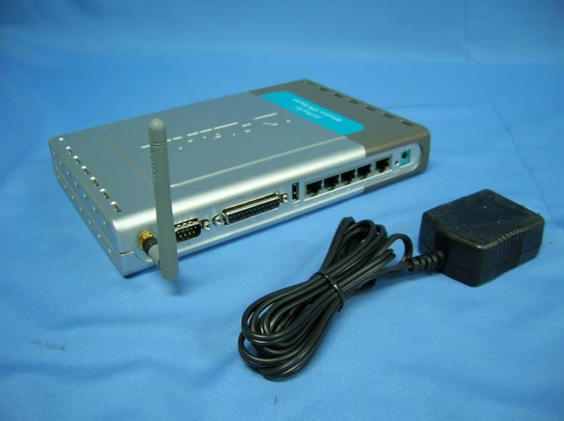
Click to zoom
Application Details
- Equipment Class
- DTS - Digital Transmission System
- Date of Grant
- Oct 22, 2006
- Application Purpose
- Original Equipment
- Date of Application
- Oct 22, 2006
- Equipment Note
- Wireless VPN Router
- Frequency Range
- 2412.00000000 - 2462.00000000
- Company
- D-Link Corporation
- Country
- United States
Documents & Files
Document Text
Text extracted from the exhibit documents filed with the FCC. Open a document above to read the original.
Users Manual
High-Speed Enhanced 2.4 GHz Manual Wireless VPN Router Building Networks for People 1/19/2004 DI-824VUP D-Link AirPlus G+ 2 Contents Package Contents................................................................................. 3 Introduction............................................................................................ 4 Wireless Basics .................................................................................... 6 Getting Started...................................................................................... 9 Using the Configuration Menu.............................................................. 11 Networking Basics.............................................................................. 72 Reset to Factory Default Settings.......................................................101 Technical Specifications.................................................................... 102 Frequently Asked Questions..............................................................103 Contacting Technical Support............................................................152 Warranty and Registration..................................................................153 Installing the Print Server Software...................................................... 68 Configuring on Windows 98se/Me Platforms.......................................70 3 Contents of Package: D-Link AirPlus G+ DI-824VUP High-Speed Enhanced 2.4GHz Wireless VPN Router Power Adapter - 5V DC / 2.5A Manual on CD Quick Installation Guide Package Contents Note: Using a power supply with a different voltage rating than the one included with the DI-824VUP will cause damage and void the warranty for this product. If any of the above items are missing, please contact your reseller. System Requirements For Configuration: Computer with Windows, Macintosh, or Linux-based operating system with an installed Ethernet adapter Internet Explorer version 6.0 or Netscape Navigator version 6.0 and above, with JavaScript enabled Ethernet-Based Cable or DSL Modem 4 Introduction The D-Link AirPlus G+ DI-824VUP Wireless Broadband Router is an enhanced 802.11b high-performance, wireless router with a printer port. It is an ideal way to extend the reach and number of computers connected to your wireless network. Unlike most 802.11g routers, the DI-824VUP is capable of data transfer speeds up to 54 Mbps (compared to the standard 11 Mbps) when used with other D- Link AirPlus Xtreme G products such as the DWL-G650 and DWL-G520 Wireless Adapters. After completing the steps outlined in the Quick Installation Guide (included in your package) you will have the ability to share information and resources, as well as share a printer wirelessly on your network. The DI-824VUP is compatible with most popular operating systems, including Macintosh, Linux and Windows, and can be integrated into a large network. This Manual is designed to help you connect the Router and D-Link AirPlus 2.4GHz Wireless Adapters into a network in Infrastructure mode. Please take a look at the Getting Started section in this manual to see an example of an Infrastructure network using the DI-824VUP . 5 Connections DHCP server support enables all networked computers to automatically receive IP addresses Wireless connection of up to 54Mbps Web-based interface for Management Access Control to manage users on the network Maximum reliability, throughput and connectivity with automatic data rate switching Stronger network security with 256-bit encryption Printer port enables connection to a network printer Connects multiple computers to an Ethernet Broadband (Cable or DSL) modem to share the Internet connection Supports VPN pass-through, providing added security Advanced Firewall features for added network security Features & Benefits Note: Please refer to the Resetting the DI-824VUP to the Factory Defualt Settings section in this manual for instructions on how to use the Reset button. WAN and LAN ports auto detect cable types (straight-through or cross-over) UPnP supported LAN ports provide connections to Ethernet- enabled devices. Pressing the Reset Button restores the router to its original factory default settings. All ports (both LAN and WAN) auto-sense cable types to accomodate straight-through or cross-over cable. Receptor for the Power Adapter. WAN port is the connection for the Ethernet cable to the Cable or DSL modem. COM port is the connection to another COM port or back- up dial-up modem. The LPT port or USB port is used to connect to your local printer. 6 LEDS LED stands for Light-Emitting Diode. The DI-824VUP has the following LEDs as described below: LED LED Activity Power A steady light indicates a connection to a power source WAN A solid light indicates connection on the WAN port. This LED blinks during data transmission WLAN A blinking light indicates that the wireless segment is ready. This LED blinks during wireless data transmission. D-Link AirPlus wireless products are based on industry standards to provide easy-to-use and compatible high-speed wireless connectivity within your home, business, or public access wireless networks. Strictly adhering to the IEEE standard, the D-Link AirPlus wireless family of products will allow you to securely access the data you want, when and where you want it. You will be able to enjoy the freedom that wireless networking delivers. A wireless local area network (WLAN) is a cellular computer network that transmits and receives data with radio signals instead of wires. Wireless LANs are used increasingly in both home and office environments, and public areas such as airports, coffee shops, and universities. Innovative ways to utilize WLAN technology are helping people to work and communicate more efficiently. Increased mobility and the absence of cabling and other fixed infrastructure have proven to be beneficial for many users. Wireless Basics Flashes once per second to indica…
Text truncated - open the document above for the full version.
Users Manual
76 Networking Basics In the window below, select the option that fits your needs. In this example, Create a Network Setup Disk has been selected. You will run this disk on each of the computers on your network. Click Next. Insert a disk into the Floppy Disk Drive, in this case drive A. 77 Networking Basics Please read the information under Here’s how in the screen below. After you complete the Network Setup Wizard you will use the Network Setup Disk to run the Network Setup Wizard once on each of the computers on your network. To continue click Next. 78 Networking Basics Please read the information on this screen, then click Finish to complete the Network Setup Wizard. The new settings will take effect when you restart the computer. Click Yes to restart the computer. You have completed configuring this computer. Next, you will need to run the Network Setup Disk on all the other computers on your network. After running the Network Setup Disk on all your computers, your new wireless network will be ready to use. 79 Networking Basics Naming your Computer To name your computer, please follow these directions: In Windows XP: Select the Computer Name Tab in the System Properties window. You may enter a Com- puter Description if you wish; this field is optional. To rename the computer and join a domain, Click Change. Click Start (in the lower left corner of the screen). Right-click on My Computer. Select Properties and click. 80 Networking Basics Naming your Computer In this window, enter the Computer name. Select Workgroup and enter the name of the Workgroup. All computers on your network must have the same Workgroup name. Click OK. Checking the IP Address in Windows XP The wireless adapter-equipped computers in your network must be in the same IP Ad- dress range (see Getting Started in this manual for a definition of IP Address Range). To check on the IP Address of the adapter, please do the following: Right-click on the Local Area Connection icon in the task bar. Click on Status. OK 81 Networking Basics Checking the IP Address in Windows XP This window will appear. Click the Support tab. Click Close. Assigning a Static IP Address in Windows XP/2000 Note: Residential Gateways/Broadband Routers will automatically assign IP Addresses to the computers on the network, using DHCP (Dynamic Host Configuration Proto- col) technology. If you are using a DHCP-capable Gateway/Router you will not need to assign Static IP Addresses. If you are not using a DHCP capable Gateway/Router, or you need to assign a Static IP Address, please follow these instructions: Go to Start. Double-click on Control Panel. 82 Networking Basics Assigning a Static IP Address in Windows XP/2000 Double-click on Network Connections. Single-click on Properties. Right-click on Local Area Connections. 83 Networking Basics Assigning a Static IP Address in Windows XP/2000 Input your IP address and subnet mask. (The IP Addresses on your network must be within the same range. For example, if one computer has an IP Address of 192.168.0.2, the other computers should have IP Addresses that are sequential, like 192.168.0.3 and 192.168.0.4. The subnet mask must be the same for all the computers on the network.) Input your DNS server addresses. (Note: If you are entering a DNS server, you must enter the IP Address of the Default Gateway.) The DNS server information will be supplied by your ISP (Internet Service Provider). Click OK. Click on Internet Protocol (TCP/IP). Click Properties. 84 Networking Basics Assigning a Static IP Address with Macintosh OSX Go to the Apple Menu and se- lect System Preferences. cClick on Network. Select Built-in Ethernet in the Show pull-down menu. Select Manually in the Con- figure pull-down menu. Input the Static IP Address, the Subnet Mask and the Router IP Address in the ap- propriate fields. Click Apply Now. 85 Networking Basics Selecting a Dynamic IP Address with Macintosh OSX Go to the Apple Menu and select System Preferences. Click on Network. Select Built-in Ethernet in the Show pull-down menu. Select Using DHCP in the Configure pull-down menu. Click Apply Now. The IP Address, Subnet mask, and the Router’s IP Address will appear in a few seconds. 86 Networking Basics Checking the Wireless Connection by Pinging in Windows XP and 2000 Checking the Wireless Connection by Pinging in Windows Me and 98 Go to Start > Run > type cmd. A window similar to this one will appear. Type ping xxx.xxx.xxx.xxx, where xxx is the IP Address of the Wireless Router or Access Point. A good wireless connection will show four replies from the Wireless Router or Acess Point, as shown. Go to Start > Run > type command. A window similar to this will appear. Type ping xxx.xxx.xxx.xxx where xxx is the IP Address of the Wireless Router or Access Point. A good wireless connection will show four replies from the wireless router or access point, as shown. 87 Networking Basics Adding and Sharing Printers in Windows XP After you have run the Network Setup Wizard on all the computers in your network (please see the Network Setup Wizard section at the beginning of Networking Basics), you can use the Add Printer Wizard to add or share a printer on your network. Whether you want to add a local printer (a printer connected directly to one computer), share an LPR printer (a printer connected to a print server), or share a network printer (a printer connected to your network through a Gateway/Router), use the Add Printer Wizard. Please follow the directions below: First, make sure that you have run the Network Setup Wizard on all of the computers on your network. On the following pages, we will show you these 3 ways to use the Add Printer Wizard: 1. Adding a local printer 2. Sharing an network printer 3. Sharing an LPR printer For help with other tasks, that we have not covered here, in home or small office net- working, see Using the Shared Documents folder and Sharing fi…
Text truncated - open the document above for the full version.
Users Manual
101 After you have tried other methods for troubleshooting your network, you may choose to Reset the DI-824VUP to the factory default settings. To hard-reset the D-Link DI-824VUP to the Factory Default Settings, please do the following: Resetting the DI-824VUP to the Factory Default Settings Use a paper clip to press the Reset button and power on. Locate the Reset button on the back of the DI-824VUP. After you have completed the above steps, the DI- 824VUP will be reset to the factory default settings. Hold for about 5 seconds (do not hold for too long) and then release. (Or, release when the status LEDflashes.) 102 Technical Specifications VPN Pass Through Function PPTP L2TP IPSec Standards IEEE 802.11b IEEE 802.3 LEDs Power WAN LAN WLAN Status COM USB Operating Temperature 32°F to 131°F ( 0°C to 55°C) Humidity 10-90% Power 5V DC / 2.5A IEEE 802.3u 100BASE-TX Fast Ethernet USB 1.1 IEEE 802.11g L = 9.25 inches (233mm) W = 6.5 inches (165mm) H = 1.375 inches (35mm) Dimensions ~2.0oz. (907g) Weight 4 x 10/100 LAN Ports (MDI/MDIX) 1 x 10/100 WAN Port (MDI/MDIX 1 COM Port (Dial-up Modem) 1 Parallel Port (DB25) 1 USB Port Ports LPT 103 Frequently Asked Questions When entering the IP Address of the DI-824VUP (192.168.0.1), you are not connecting to the Internet or have to be connected to the Internet. The device has the utility built-in to a ROM chip in the device itself. Your computer must be on the same IP subnet to connect to the web-based utility. To resolve difficulties accessing a Web utility, please follow the steps below. Step 1 Verify physical connectivity by checking for solid link lights on the device. If you do not get a solid link light, try using a different cable or connect to a different port on the device, if possible. If the computer is turned off, the link light may not be on. The following connections require a Crossover Cable: Computer to Computer Computer to Uplink Port Computer to Access Point Computer to Print Server Computer/XBOX/PS2 to DWL-810 Computer/XBOX/PS2 to DWL-900AP+ Uplink Port to Uplink Port (hub/switch) Normal Port to Normal Port (hub/switch) The following connections require a Straight-through Cable: Computer to Residential Gateway/Router Computer to Normal Port (hub/switch) Access Point to Normal Port (hub/switch) Print Server to Normal Port (hub/switch) Uplink Port to Normal Port (hub/switch) Rule of Thumb: ”If there is a link light, the cable is right.” What type of cable should I be using? Why can ́t I access the Web-based configuration? 104 Frequently Asked Questions (continued) What type of cable should I be using? (continued) What ́s the difference between a crossover cable and a straight-through cable? The wiring in crossover and straight-through cables are different. The two types of cable have different purposes for different LAN configurations. EIA/TIA 568A/568B define the wiring standards and allow for two different wiring color codes as illustrated in the following diagram. *The wires with colored backgrounds may have white stripes and may be denoted that way in diagrams found elsewhere. How to tell straight-through cable from a crossover cable: The main way to tell the difference between the two cable types is to compare the wiring order on the ends of the cable. If the wiring is the same on both sides, it is straight-through cable. If one side has opposite wiring, it is a crossover cable. All you need to remember to properly configure the cables is the pinout order of the two cable ends and the following rules: A straight-through cable has identical ends A crossover cable has different ends It makes no functional difference which standard you follow for straight-through cable ends, as long as both ends are the same. You can start a crossover cable with either standard as long as the other end is the other standard. It makes no functional difference which end is which. The order in which you pin the cable is important. Using a pattern other than what is specified in the above diagram could cause connection problems. When to use a crossover cable and when to use a straight-through cable: Computer to Computer – Crossover Computer to an normal port on a Hub/Switch – Straight-through Computer to an uplink port on a Hub/Switch – Crossover Hub/Switch uplink port to another Hub/Switch uplink port – Crossover Hub/Switch uplink port to another Hub/Switch normal port – Straight-through Why can ́t I access the Web-based configuration? (continued) 105 Step 3 Configure your Internet settings. Step 2 Disable any Internet security software running on the computer. Software firewalls like Zone Alarm, Black Ice, Sygate, Norton Personal Firewall, etc. might block access to the configuration pages. Check the help files included with your firewall software for more information on disabling or configuring it. Frequently Asked Questions (continued) Click to the Connection tab and set the dial- up option to Never Dial a Connection. Click the LAN Settings button. Nothing should be checked. Click OK. Go to the Advanced tab and click the Restore Defaults button to restore these settings to their facotry defaults. Click OK. Go to the desktop and close any open windows. Go to Start > Settings > Control Panel. Double click the Internet Options Icon. From the Security tab, click the Default Level button to restore the settings to their defaults. Why can ́t I access the Web-based configuration? (continued) 106 Frequently Asked Questions (continued) Step 4 Check your IP address. Your computer must have an IP address in the same range of the device you are attempting to configure. Most D-Link devices use the 192.168.0.X range. How can I find my IP Address in Windows 95, 98, or ME? Step 1 Click on Start, then click on Run. Step 2 The Run Dialogue Box will appear. Type winipcfg in the text field and click OK. Step 3 The IP Configuration window will appear, displaying your Ethernet Adapter Information. Select your…
Text truncated - open the document above for the full version.
Block Diagram
55 44 33 22 11 D D C C B B A A TRDYBINTABDEVSELBCBE2BCCLKIRDYBCBE1BMRSTBFRAMEBCBE3BPAR AD[0..31] REQBSTOPBCBE0BPERRBSERRBIDSELGNTBRFTXDIS#LD2P_24GCLKRUNBLD1P_ACT TX_BB_I+RFRX_PERX_BB_Q-TX_BB_I-RX_BB_I+40MIRX_BB_I-RFTX_PERX_BB_Q+SYNDATATX_BB_Q-TX_BB_Q+RF_LE-G#SYNCLKIREF LD2_YN5 RADIO_PD# PA_RFING ANTSEL_PANTSEL_N RFIN_G PA_PE_G Mini PCI I/F and Power4-MINIPCI.SCH AD[0..31] CCLK CBE3BCBE2BCBE1BCBE0B PAR FRAMEB IRDYB TRDYB DEVSELB MRSTB INTAB STOPB SERRBPERRB IDSEL RFTXDIS# REQB GNTB LD2P_24G CLKRUNB LD1P_ACT LD2_YN5 MAC RT25613-RT2561-MPCI AD[0..31]CCLKCBE3BPARFRAMEBIRDYBMRSTBINTABREQBSTOPBCLKRUNB TX_BB_Q+ TX_BB_Q- TX_BB_I+ TX_BB_I- RX_BB_Q+ RX_BB_I+ RX_BB_I- RX_BB_Q- ANTSEL_N ANTSEL_P RFRX_PE RFTX_PE RF_LE-G# SYNDATA SYNCLK PA_PE_G RADIO_PD# 40MI CBE2BCBE1BCBE0BTRDYBDEVSELBGNTBSERRBPERRBIDSEL IREF RFTXDIS#LD2P_24GLD1P_ACTLD2_YN5 Transceiver RT2527 1-RT2527-XTAL RFRX_PERFTX_PERF_LE-G#SYNDATASYNCLK40MIRADIO_PD#RX_BB_I-RX_BB_I+RX_BB_Q-RX_BB_Q+TX_BB_I-TX_BB_I+TX_BB_Q-TX_BB_Q+ RFIN_G PA_RFING IREF PA TQP777002 and TX/RX 2-PA-TQP777002 PA_PE_GANTSEL_PANTSEL_N RFIN_G PA_RFING
Block Diagram
DI-824VUP Block Diagram CPU SDRAM Flash SWITCH Transform LAN*4 WAN*1 USB port DB9 COM port DB25 Print port Crystal 25MHz Mini PCI 25MHz MII1 MII2 Ant.
External Photos
Report No: 069H011-RF-US-P05V01 Page: 73 of 81 Version:1.0 Attachement ¾ EUT Photograph (1) EUT Photo (2) EUT Photo
ID Label/Location Info
D-Link Corporation No. 289, Sinhu 3rd Rd., Neihu District, Taipei City 114, Taiwan, R.O.C. FCC ID.: KA2DI824VUPB1 FCC ID and DoC Label The FCC ID and DoC Label will be placed on the equipment as shown in the photograph below. Wireless VPN Router Model No.: DI-824VUP F F C C C C I I D D : : KA2DI824VUPB1 This device complies with Part 15 of the FCC Rules. Operation is subject to the following two conditions: (1) this device may not cause harmful interference and (2) this device must accept any interference received, including interference that may cause undesired operation. S/N: Made in Taiwan Trade name: D-Link Model number.: DI-824VUP
Internal Photos
Report No: 069H011-RF-US-P05V01 Page: 74 of 81 Version:1.0 (3) EUT Photo (4) EUT Photo Report No: 069H011-RF-US-P05V01 Page: 75 of 81 Version:1.0 (5) EUT Photo (6) EUT Photo Report No: 069H011-RF-US-P05V01 Page: 76 of 81 Version:1.0 (7) EUT Photo (8) EUT Photo Report No: 069H011-RF-US-P05V01 Page: 77 of 81 Version:1.0 (9) EUT Photo (10) EUT Photo Report No: 069H011-RF-US-P05V01 Page: 78 of 81 Version:1.0 (11) EUT Photo Report No: 069H011-RF-US-P05V01 Page: 79 of 81 Version:1.0 (12) EUT Photo Report No: 069H011-RF-US-P05V01 Page: 80 of 81 Version:1.0 (13) EUT Photo Report No: 069H011-RF-US-P05V01 Page: 81 of 81 Version:1.0 (14) EUT Photo
RF Exposure Info
Report No. 069H011-RF-US-Exp Page: 1 of 4 Version:1.0 RF Exposure Evaluation declaration Product Name :Wireless VPN Router Model No. :DI-824VUP FCC ID. :KA2DI824VUPB1 Applicant : D-Link Corporation Address : No. 289, Sinhu 3rd Rd., Neihu District, Taipei City 114, Taiwan, R.O.C. Date of Receipt : 2006/09/05 Date of Declaration : 2006/09/21 Report No. : 069H011-RF-US-Exp The declaration results relate only to the samples calculated. The declaration shall not be reproduced except in full without the written approval of QuieTek Corporation. Report No. 069H011-RF-US-Exp Page: 2 of 4 Version:1.0 1. RF Exposure Evaluation 1.1. Limits According to FCC 1.1310: The criteria listed in the following table shall be used to evaluate the environment impact of human exposure to radio frequency (RF) radiation as specified in 1.1307(b) LIMITS FOR MAXIMUM PERMISSIBLE EXPOSURE (MPE) Frequency Range (MHz) Electric Field Strength (V/m) Magnetic Field Strength (A/m) Power Density (mW/cm 2 ) Average Time (Minutes) (A) Limits for Occupational/ Control Exposures 300-1500 -- -- F/300 6 1500-100,000 -- -- 5 6 (B) Limits for General Population/ Uncontrolled Exposures 300-1500 -- -- F/1500 6 1500-100,000 -- -- 1 30 F= Frequency in MHz Friis Formula Friis transmission formula: Pd = (Pout*G)/(4*pi*r 2 ) Where Pd = power density in mW/cm 2 Pout = output power to antenna in mW G = gain of antenna in linear scale Pi = 3.1416 R = distance between observation point and center of the radiator in cm Pd id the limit of MPE, 1 mW/cm 2 . If we know the maximum gain of the antenna and the total power input to the antenna, through the calculation, we will know the distance r where the MPE limit is reached. 1.2. Test Procedure Software provided by client enabled the EUT to transmit and receive data at lowest, middle and highest channel individually. The temperature and related humidity: 18°Cand 78% RH. Report No. 069H011-RF-US-Exp Page: 3 of 4 Version:1.0 1.3. Test Result of RF Exposure Evaluation Product Wireless VPN Router Test Mode Mode 1: Transmit Test Condition RF Exposure Evaluation Antenna Gain Antenna Gain: The maximum Gain measured in fully anechoic chamber is 1.8dBi or 1.513dBi in linear scale. Output Power Into Antenna & RF Exposure Evaluation Distance: IEEE 802.11b Channel Channel Frequency (MHz) Output Power to Antenna (mW) Power Density at R = 20 cm (mW/cm 2 ) 1 2412.00 198.1527 0.0597 6 2437.00 176.1976 0.0531 11 2462.00 148.2518 0.0446 The power density Pd (4th column) at a distance of 20 cm calculated from the Friis transmission formula is far below the limit of 1 mW/cm 2 . Report No. 069H011-RF-US-Exp Page: 4 of 4 Version:1.0 Product Wireless VPN Router Test Mode Mode 1: Transmit Test Condition RF Exposure Evaluation Antenna Gain Antenna Gain: The maximum Gain measured in fully anechoic chamber is 1.8dBi or 1.513dBi in linear scale. Output Power Into Antenna & RF Exposure Evaluation Distance: IEEE 802.11g Channel Channel Frequency (MHz) Output Power to Antenna (mW) Power Density at R = 20 cm (mW/cm 2 ) 1 2412.00 114.0250 0.0343 6 2437.00 106.4143 0.0320 11 2462.00 98.6279 0.0297 The power density Pd (4th column) at a distance of 20 cm calculated from the Friis transmission formula is far below the limit of 1 mW/cm 2 .
Schematics
55 44 33 22 11 D D C C B B A A TRDYBINTABDEVSELBCBE2BCCLKIRDYBCBE1BMRSTBFRAMEBCBE3BPAR AD[0..31] REQBSTOPBCBE0BPERRBSERRBIDSELGNTBRFTXDIS#LD2P_24GCLKRUNBLD1P_ACT TX_BB_I+RFRX_PERX_BB_Q-TX_BB_I-RX_BB_I+40MIRX_BB_I-RFTX_PERX_BB_Q+SYNDATATX_BB_Q-TX_BB_Q+RF_LE-G#SYNCLKIREF LD2_YN5 RADIO_PD# PA_RFING ANTSEL_PANTSEL_N RFIN_G PA_PE_G Mini PCI I/F and Power4-MINIPCI.SCH AD[0..31] CCLK CBE3BCBE2BCBE1BCBE0B PAR FRAMEB IRDYB TRDYB DEVSELB MRSTB INTAB STOPB SERRBPERRB IDSEL RFTXDIS# REQB GNTB LD2P_24G CLKRUNB LD1P_ACT LD2_YN5 MAC RT25613-RT2561-MPCI AD[0..31]CCLKCBE3BPARFRAMEBIRDYBMRSTBINTABREQBSTOPBCLKRUNB TX_BB_Q+ TX_BB_Q- TX_BB_I+ TX_BB_I- RX_BB_Q+ RX_BB_I+ RX_BB_I- RX_BB_Q- ANTSEL_N ANTSEL_P RFRX_PE RFTX_PE RF_LE-G# SYNDATA SYNCLK PA_PE_G RADIO_PD# 40MI CBE2BCBE1BCBE0BTRDYBDEVSELBGNTBSERRBPERRBIDSEL IREF RFTXDIS#LD2P_24GLD1P_ACTLD2_YN5 Transceiver RT2527 1-RT2527-XTAL RFRX_PERFTX_PERF_LE-G#SYNDATASYNCLK40MIRADIO_PD#RX_BB_I-RX_BB_I+RX_BB_Q-RX_BB_Q+TX_BB_I-TX_BB_I+TX_BB_Q-TX_BB_Q+ RFIN_G PA_RFING IREF PA TQP777002 and TX/RX 2-PA-TQP777002 PA_PE_GANTSEL_PANTSEL_N RFIN_G PA_RFING 55 44 33 22 11 D D C C B B A A 1.8VD 1.8VD 3.3VD 3.3VD 3.3VD GND PARCBE1B 3.3VD CBE0B CLKRUNB GNTBIRDYBPERRBSTOPBMRSTBDEVSELB GND INTABFRAMEBREQBSERRBTRDYB 3.3VD 1.8VD LD1P_ACT LED_RDYG#LED_LKACT# LD2P_24G DEVSELBSERRBPERRBSTOPBTRDYBCLKRUNB 1.8VD FRAMEBIRDYBCBE2B 1.8VD EEDIEECS ORG 3.3VD3.3VD3.3VD3.3VD 3.3VD 1.8VD IDSEL INTAB REQB GNTB MRSTBREQB MRSTB CBE3BGNTB CBE3B INTABIDSEL AD23 AD30 AD7AD12AD13AD5AD18AD10 AD31 AD29 AD27 AD22 AD21 AD19AD3AD9 AD24 AD25 AD16 AD[0..31] AD8AD2 AD28 AD26 AD4AD17 AD20 AD14AD15 AD6AD11AD1AD0 CCLK CCLK 1.8VC 1.8VC 1.8VC VREF25P 3.3VD 1.8VD 1.8VD 1.8VA1.8VC1.8VA EECS EEDO EEDO RFTX_PERFRX_PEANTSEL_NANTSEL_PRADIO_PD# GND SYNDATA PA_PE_G TX_BB_Q-TX_BB_I+TX_BB_Q+TX_BB_I- VREF IREF TSSI_AG 3.3VARF_LE0 LED_RDYA# LD2_YN5 1.8VC 1.8VA 3.3VA GND RX_BB_Q-RX_BB_Q+RX_BB_I-RX_BB_I+ GND GPIO5 RF_LE-G# RF_DATA0 VREF25N 1.8VDPLL 1.8VD 1.8VDPLL GND 1.8VDPLL 1.8VD EESK 3.3VD3.3VD 3.3VD 3.3VD 3.3VD3.3VD3.3VD3.3VD3.3VD 3.3VD 3.3VD 3.3VD GND EESK EEDI 1.8VA1.8VAVREFP GND GND GND 1.8VA GND GND GND GND GND VREFN GND GND VCCA PA_PWR SYNCLK RF_CLK TR_SW0 TR_SW0 3.3VDGND RFTXDIS# AD[0..31] PAR CBE1BCBE0B LD2P_24GLD1P_ACT DEVSELB SERRBPERRBSTOPBTRDYB CLKRUNBFRAMEB IRDYBCBE2B MRSTB INTABCBE3B CCLK IDSEL RFTX_PERFRX_PEANTSEL_NANTSEL_PRADIO_PD# PA_PE_G TX_BB_I+TX_BB_I-TX_BB_Q-IREFRX_BB_I+RX_BB_I-RX_BB_Q-RX_BB_Q+ 40MI TX_BB_Q+ LD2_YN5 RFTXDIS# REQB GNTB SYNDATARF_LE-G#SYNCLK GND 3.3VD GND 1.8VD GND GND 3.3VD GND GND GND 3.3VA GND GND VCCA GND 1.8VC GND 3.3VA GND GND 1.8VD 1.8VA 3.3VD GND GND GND VCCA GND3.3VD 1 2 R6 0 ohm/SB R6 0 ohm/SB 12 C4840.1uFC4840.1uF 1 2 R279 510 R279 510 12 D2 LED D2 LED 12 C164 0.1uF C164 0.1uF 1 2 R273 100 R273 100 1 2 R276 0 ohm R276 0 ohm 12 C252 10pF C252 10pF 12 C299 0.1uF C299 0.1uF 1 2 C302 1uF C302 1uF 1 2 R2 330 R2 330 1 2 C301 1uF C301 1uF 12 D3 LED D3 LED 12 C4870.1uFC4870.1uF 1357 2468 RA4 RA 4.7K*4 RA4 RA 4.7K*4 1 2 C303 1uF C303 1uF 1 2 R227 10K R227 10K 12 D1 LED D1 LED 1 2 R274 100 R274 100 12 C172 0.1uF C172 0.1uF 12 C4830.1uFC4830.1uF 12 C167 0.1uF C167 0.1uF 12 C1730.1uFC1730.1uF 12 C2610.1uFC2610.1uF 1 2 R1 4.7K R1 4.7K 1 2 R4 330 R4 330 12 C1650.1uFC1650.1uF 12 R1610KR1610K 1 2 R163 4.7K R163 4.7K 12 C477 0.1uF C477 0.1uF 12 C12 0.1uF C12 0.1uF 1 2 R207 820 R207 820 12 C265 0.1uF C265 0.1uF GPIO0 113 RFTXI_P0 10 RFTXI_N0 11 RFTXQ_P0 12 RFTXQ_N0 13 IREF 9 VREFP 24 VCC18A 18 TSSI_A0 15 NC 27 NC 28 NC 31 NC 32 TR_PE 121 VCC18A 23 RF_SCLK 3 NC 4 RF_PE 120 TR_SW0 122 TR_SWN0 123 RADIO_PE 126 PA_PE_G 6 ANSEL_P 127 ANSEL_N 128 VCCIO 114 EEDO 119 EEDI 118 EESK 117 EECS 116 INTA_N 44 RST_N 46 VDD18 43 VCCIO 65 GNT_N 48 REQ_N 47 AD[31] 49 AD[30] 50 AD[29] 51 AD[28] 52 AD[27] 53 AD[26] 54 VCCIO 55 AD[25] 57 AD[24] 58 CBE[3]_N 59 IDSEL 61 AD[23] 60 AD[22] 62 AD[21] 63 AD[20] 64 AD[19] 66 AD[18] 68 VDD18 75 AD[17] 69 AD[16] 70 VCCIO 74 CLK_PCI 45 CBE[2]_N 71 FRAME_N 73 IRDY_N 72 CLKRUN_N 76 TRDY_N 77 DEVSEL_N 81 STOP_N 79 VCCIO 84 PERR_N 80 SERR_N 78 PAR 67 CBE[1]_N 82 AD[15] 83 AD[14] 85 VCCIO 94 AD[13] 86 AD[12] 87 AD[11] 88 AD[10] 90 AD[9] 91 VCCIO 125 AD[8] 92 CBE[0]_N 93 AD[7] 95 AD[6] 96 AD[5] 97 AD[4] 98 VDD18 89 AD[3] 99 AD[2] 100 VCCIO 103 AD[1] 101 AD[0] 102 LED_ACT_N 104 LED_RDYG_N 106 GPIO5 107 GPIO4 108 GPIO3 109 GPIO2 111 GPIO1 112 VCC18D 14 VCC18A 26 VREFN 25 VCC18A 30 V-PA_PWR 7 VCC33A 17 VDD18 124 PLLDVDD 41 PLLTAVDD 40 PLLAVDD 39 PLLCLK 42 VCC18A 29 VDD18 56 PA_PE_A 8 NC 5 VREF025N 38 VREF025P 37 VREF 36 VCC18D 35 VCC18D 34 VCC18D 33 VDD18 115 VDD18 110 LED_RDYA_N 105 RF_SDATA0 2 RF_SCS_N0 1 TSSI_G0 16 RFRXI_P0 19 RFRXI_N0 20 RFRXQ_P0 21 RFRXQ_N0 22 GND 129 U31 RT2561-LQFP128 U31 RT2561-LQFP128 12 C1660.1uFC1660.1uF 12 C4780.1uFC4780.1uF 1357 2468 RA2 RA 4.7K*4 RA2 RA 4.7K*4 12 C4955pFC4955pF 12 C4850.1uFC4850.1uF 12 t RT1 CT6103-3435-5P t RT1 CT6103-3435-5P 12 C4880.1uFC4880.1uF 1357 2468 RA3 RA 4.7K*4 RA3 RA 4.7K*4 1 2 R206 10K R206 10K 1 2 R275 0 ohm R275 0 ohm 12 C337 0.1uF C337 0.1uF 12 C490 0.1uF C490 0.1uF 1 2 R280 510 R280 510 12 C2600.1uFC2600.1uF CS 1 SK 2 DI 3 DO 4 GND 5 N/C 6 N/C 7 VDD 8 U3093C66-TSSOPU3093C66-TSSOP 12 C2981uFC2981uF 12 C479 0.1uF C479 0.1uF 1 2 C300 1uF C300 1uF 12 C4965pFC4965pF 12 R1720KR1720K 12 C8 0.1uF C8 0.1uF 1 2 R5 330 R5 330 1 2 R272 100 R272 100 1 2 R3 330 R3 330 55 44 33 22 11 D D C C B B A A SYNCLK RF_LE-G# GND RF_LE-G# GND RFLDOBP IREF SYNDATA RADIO_PD# SYNDATA IREF SYNCLK 40MX1 RX_BB_Q- RX_BB_Q- RFOUTG+RFING+ PA_RFING GND GNDGNDGND VCCAVCCA RFIN_G RFOUTG-RFING- GND TXR_VO3 VCTRL1 TXR_VO3 GND TXR_VO2 VCCA C_VCC VE RFRC C_VCC TXR_VO3 GNDGND RFRX_PE RFRX_PE RFTX_PE RFTX_PE VCCA VCCA VCCA VCCA VCCARX_BB_Q+ RX_BB_Q+ RX_BB_I- RX_BB_I- RX_BB_I+ RX_BB_I+ TX_BB_I- RF_VCCD VCCA GND 1.8VA 1.8VA GND GND GND GND GND3.3VA 3.3VD VCCA GND VCCA GND GND GND TX_BB_I- TX_BB_Q- TX_BB_Q-TX_BB_Q+ TX_BB_Q+ TX_BB_I+ TX_BB_I+ TXR_VO2 TXR_VO2 40MI TXR-40MO GND RFIN_F F40M 40MX2 GND RF_LE-G#IREF RADIO_PD# SYNCLKSYNDATA RX_BB_Q- RFIN_G PA_RFING RFTX_PERFRX_PE…
Text truncated - open the document above for the full version.
Test Report
Report No: 069H011-RF-US-P05V01 Page: 1 of 81 Version:1.0 Test Report Product Name:Wireless VPN Router Model No. …
Text truncated - open the document above for the full version.
Contact Information
Applicant
Brett Adair(General Counsel)
Technical Contact
QuieTek CorporationGeorge Chen
[email protected]+886-2-8601-3788
No. 5-22, Ruei-Shu Valley,Ruei-Ping Tsuen, · Lin-Kou Shiang,Taipei, · Taiwan
Test Firm
QuieTek CorporationWarren Lin
Technical Specifications
| # | Rule Parts | Frequency Range | Power Output |
|---|---|---|---|
| 1 | 15C | 2.41 GHz - 2.46 GHz | 199.00 mW |
Other Applications from D-Link Corporation

KA2CS6012A1
Jul 07, 20262K Fixed Indoor Cloud Camera, 2K Fixed Indoor Wi-Fi Camera
Equipment Class
DTS - Digital Transmission SystemKA2AE65UA1
Mar 02, 2026Wi-Fi 7 BE6500 USB 3.0 Dongle
Equipment Class
NII - Unlicensed National Information Infrastructure TXKA2APE9560A1
Nov 17, 2025BE9500 Celling mount Access Point
Equipment Class
6ID - 15E 6 GHz Low Power Indoor Access PointKA2AX9UA1
Dec 04, 2024AX900 Wi-Fi 6 USB Adapter, Wi-Fi 6 AX900 USB 2.0 Dongle
Equipment Class
DSS - Part 15 Spread Spectrum TransmitterKA2AC13UA1
Dec 04, 2024AC1300 Wi-Fi 5 USB Adapter, Wi-Fi 5 AC1300 USB 2.0 Dongle
Equipment Class
DTS - Digital Transmission System