KA2DIR320A1802.11g Wireless Cable/DSL Internet Gateway w/USB
D-Link Corporation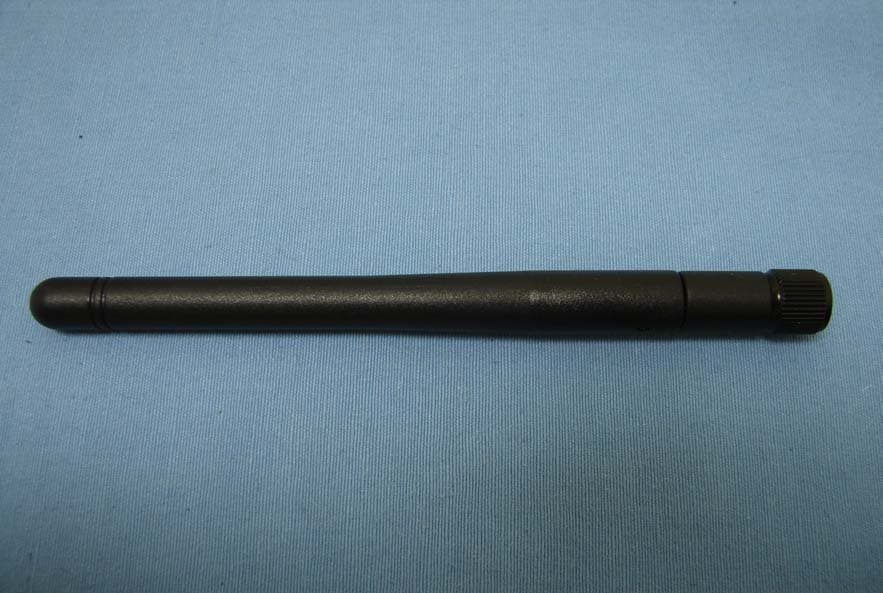
Click to zoom
Application Details
- Equipment Class
- DTS - Digital Transmission System
- Date of Grant
- Oct 31, 2007
- Application Purpose
- Original Equipment
- Date of Application
- Oct 31, 2007
- Equipment Note
- 802.11g Wireless Cable/DSL Internet Gateway w/USB
- Frequency Range
- 2412.00000000 - 2462.00000000
- Company
- D-Link Corporation
- Country
- United States
Documents & Files
Document Text
Text extracted from the exhibit documents filed with the FCC. Open a document above to read the original.
Users Manual
Table of Contents 1 Table of Contents P ACKAGE C ONTENTS .......................................................................................... 1 S YSTEM R EQUIREMENTS ..................................................................................... 1 F EATURES .......................................................................................................... 2 HARDWARE OVERVIEW .................................................................................... 3 LED Indicators .............................................................................................. 4 INSTALLATION .................................................................................................... 5 B EFORE Y OU B EGIN ............................................................................................ 5 W IRELESS I NSTALLATION C ONSIDERATIONS .......................................................... 6 C ONNECT TO C ABLE /DSL/S ATELLITE M ODEM ...................................................... 7 Connect to Anot her Router........................................................................... 8 CONFIGURATION ................................................................................................ 9 Web-based Configur ation Ut ility................................................................... 9 C ONFIGURE I NTERNET C ONNECTION - S ETUP W IZARD ........................................ 10 Internet Connecti on Setup Wizard ..............................................................11 C ONFIGURE I NTERNET C ONNECTION – M ANUAL S ETUP ...................................... 18 Dynamic IP Address ................................................................................... 19 Static IP Address ........................................................................................ 20 PPPoE ........................................................................................................ 21 PPTP .......................................................................................................... 23 L2TP ........................................................................................................... 25 BigPond ...................................................................................................... 26 PPTP Russia .............................................................................................. 27 PPPoE Russia ............................................................................................ 28 C ONFIGURE W IRELESS C ONNECTION - S ETUP W IZARD ....................................... 29 Wireless Connection Setup Wizard............................................................ 30 W IRELESS C ONNECTION – M ANUAL S ETUP ........................................................ 33 Wireless Network Settings.......................................................................... 34 Wi-Fi Protect ed Set up................................................................................. 35 Wireless Securi ty - WEP ............................................................................ 36 Wireless Securi ty – WP A/EAP.................................................................... 37 Wireless Securi ty – WP A/PSK.................................................................... 38 LAN S ETUP ...................................................................................................... 39 Router IP Settings....................................................................................... 40 LAN DHCP Server Settings ........................................................................ 41 P RINTER S ETUP ................................................................................................ 42 Printer Set up Wizard................................................................................... 42 T IME AND D ATE ................................................................................................. 45 P ARENTAL C ONTROL .......................................................................................... 46 A DVANCED S ETUP ............................................................................................. 47 Port Forw arding .......................................................................................... 48 Application Rules ........................................................................................ 49 Access Control............................................................................................ 50 Firewall & DMZ ........................................................................................... 51 Advanced Wireless ..................................................................................... 52 Advanced Network...................................................................................... 54 Routing ....................................................................................................... 55 QoS Engine ................................................................................................ 56 Guest Zone ................................................................................................. 57 Traffic Management .................................................................................... 59 M AINTENANCE ................................................................................................... 60 Device Admini stration ................................................................................. 60 Save and Re store ....................................................................................... 61 Firmware Update ........................................................................................ 62 Table of Contents 2 DDNS Setting ............................................................................................. 63 System Check ..........................................................................................…
Text truncated - open the document above for the full version.
Users Manual
Section 1 - Product Overview D-Link DIR-320 User Manual 3 Hardware Overview Power Insert Use the adapter shipped with the Router to connect to p ower source Internet Port The auto MID/MDIX Internet (WAN) port is used for connection to a broadband cable or ADSL modem. Use the included Ethernet cable for the connection to a broadband device. USB Port Connect to a single computer or network printer. Use included USB cable to make connection. LAN Ports Use the Ethernet LAN ports to connect the Router to computers or network devices on an Ethernet LAN. Use Ethernet cables for all LAN connections. Reset Button To manually reset, depress button with the power on for at least seven seconds Section 1 - Product Overview D-Link DIR-320 User Manual 4 LED Indicators Power Steady green light indicates the unit is powered on. When the device is powered off this remains dark. A red colored Power LED indicates system failure. USB (Printer Port) A steady green light indicates a valid link. This light will blink when there is activity currently passing through the USB port. WAN (Internet) A steady green light indicates a valid WAN connection. A blinking green light indicates activity on the WAN (Internet) interface. LAN A steady green light indicates a valid link on startup. This light will blink when there is activity currently passing through the Ethernet port. WLAN Steady green light indicates a wireless connection. A blinking green light indicates activity on the Wireless LAN interface. Status Blinking green light indicates normal function. Dark indicator means the system has failed. Section 2 – Installation D-Link DIR-320 User Manual 5 Installation This section will walk you through the installation process. Plac ement of the Wireless Broadband Rout er is very important. Do n ot place the router in an enclosed area such as a closet, cabinet, or in the attic or gar age. Place the Wireless Broadband Router in a location where it can be easily connected to Ethernet devices, the telephon e line as well as to a power source. Before You Begin Please read and make sure you understand all the prerequisites for proper installation of your new router. Have all the necessa ry information and equipment on hand before beginn ing the installation. Operating Systems The DIR-320 uses an HTML-based web interfac e for setup and management. The web configur ation manager may be accessed using any operating system capable of running web browser software, incl uding Windows 98 SE, Windows ME, Wi ndows 2000, Windows XP, and Wi ndows Vista. Web Browser Any common web browser can be used to confi gure the router using the w eb configuration management software. The web browser mus t have JavaScript enabled. JavaScript is enabled by def ault on many browsers. Make sure JavaScri pt has not been disabled by other soft ware (such as virus protection or web user security pa ckages) that may be runni ng on your computer. Ethernet Port (NIC Adapter) Any computer that uses the router must be able to connect to it through the Ethernet port on th e router. Most notebook computer s and fully assembled desktop computers are now sold wit h an Ethernet port already installed. If your computer does not have an Ethernet po rt, you must install an Ethernet NIC adapter bef ore you can use the router. Wireless LAN Computers using the Wireless network can access the Internet or use the embedded 802. 1g wireless access point. Wireless worksta tions must have an 802.1g or 802.1b wireless net work card installed to use the Wireless Broadba nd Router. In addition the workstations mus t be configured to operate on the same channel and SSI D as the Wireless Broadband Router . If wireless security is used , the wireless workstations must be properly configured for the security settings used. Section 2 – Installation D-Link DIR-320 User Manual 6 Wireless Installation Considerations The D-Link wireless router lets you access your network using a wireless connection from virtua lly anywhere within the operatin g range of your wireless network. Keep in mind, however, that the number, thick ness and location of walls, ceilings , or other objects that the wireless signals must pass through, may limit the range. Typical r anges vary depending on the types of material s and background RF (radio frequency) noise in your home or business. The key to maximizing wirele ss range is to follow these basic guidelines: 1. Keep the number of walls and ce ilings between the D-Link router and other network devices to a minimum – each wall or ceilin g can reduce your adapter ' s range from 3-90 feet (1-30 meters.) Posi tion your devices so that the number of walls or ceilings is minimized. 2. Be aware of the direct line between network devices. A wall that is 1.5 feet thick (.5 mete rs), at a 45-degree angle appears to be almost 3 feet (1 meter) thick. At a 2-degree angle it looks over 42 feet (14 mete rs) thick! Position devices so that the signal will tra vel straight through a wall or ceiling (instead of at an angle) for better reception. 3. Building Materials make a difference. A solid metal door or aluminum studs may have a negative effect on range. Try to posit ion access points, wireless routers, and com puters so that the signal passes through drywall or open doorways. Materials and objects such as glass, steel, metal, walls with insulation, water (f ish tanks), mirrors, file cabinets, bri ck, and concrete will degrade your wireless signal. 4. Keep your product away (at least 3-6 feet or 1-2 meters) from electrical devices or appliances that generate RF noise. 5. If you are using 2.4GHz cordless phones or X-10 (wireless products such as ceiling fans, lights, and home security systems), yo ur wireless connection may degrade dramatic ally or drop completely. Make sure your 2.4GHz phone base is as far away from your wire less devices as possible. The base transmits a signal even if the phone in not in use. Section 2 – Installation D-Link DIR-320 User Manual 7 Connect…
Text truncated - open the document above for the full version.
Users Manual
Section 3 – Configuration D-Link DIR-320 User Manual 9 Configuration This section will show you how to set up and configure your new D-Link router using the Web-ba sed configuration utility. Web-based Configuration Utility Connect to the Router To configure the WAN connection used by the r outer it is first necessary to communica te with the router through its management interface, which is HTML-based and can be accessed using a web browser. The easiest way to make sure your computer has the correct IP settings is t o configure it to use the DHCP server in the router. The next section describes how to change the IP configuration for a computer running a Wi ndows operating system to be a DHCP client. To access the configuration utility, open a web-browser such as Internet Explorer and enter the IP address of the router ( 192.168.0.1 ). Type “admin ” for the User Name in the entry field. If this is the first time configuring the router, leave the Password field blank, there is no default password. If you get a Page Cannot be Displayed error, please refer to the Troubleshooting section for assistance. Section 3 – Configuration D-Link DIR-320 User Manual 10 Configure Internet Connection - Setup Wizard When you successfully connect to the web manager, the main Internet Connection menu displays two options for configuring the Internet connection. Click on he Internet Connection Setup Wizard to quickly configure the Internet connection. The Setup Wizard procedure is described in the pages following this one. To configure the connection in more detail, click on the Manual Internet Connection Setup button. Manual Internet connection setup is described in Internet Connection - Configure Internet Connection – Manual Setup on page 18 below. Section 3 – Configuration D-Link DIR-320 User Manual 11 Internet Connection Setup Wizard Use the Internet Connection Setup Wizard to quickly configure the Internet connection. Setup Wizard Click the Internet Connection Setup Wizard button and follow the instructions in the menus that appear. The initial window summarizes the se tup process. These steps are as follows: 1. Set the new password. 2. Select the time zone. 3. Configure the connection to the Internet. 4. Save settings and reboot the router. Click the Next button to proceed. You may stop using the Setup Wizard at any time by clicking the Cancel button. I Change the administrator account passw ord, enter a new password in the first Password entry field, re-type it exac tly as before in the Verify Password field, and click Next . If you wish to return to the previous window during the setup process, click the Prev button. Section 3 – Configuration D-Link DIR-320 User Manual 12 Choose the time zone you are in from the pull-down menu and click Next . This sets the system time used for the router. If you wish to return to the previous window during the setup process, click the Prev button. Select the Internet Connection Type us ed for the Internet connection. Your ISP has given this information to you. The connection types available are DHCP (Dynamic IP Address) , Username/Password (PPPoE) , Username/Password (PPTP) , Username/Password (L2TP) , Username/Password (Bigpond) , Static IP Address Connection , Russia PPTP (Dual Access) and Russia PPPoE (Dual Access) . Each connection type has different settings that are configured in the next menu Select the Connection Type specific to your service and click Next . Follow the instructions below fo r the type of connection you have selected. Section 3 – Configuration D-Link DIR-320 User Manual 13 DHCP (Dynamic IP Address) - For Dynamic IP Address connections, you may want to copy the MAC addr ess of your Ethernet adapter to the router. Some ISPs use the unique MAC address of your computer’s Ethernet adapter for identification and for IP address assignment (DHCP) when you first access their network. Th is can prevent the router (which has a different MAC address) from being allowed access to the ISP’s network (and the Internet). To clone the MAC address of your computer’s Ethernet adapter, click the Clone MAC Address button. Click Next to continue. Username/Password (PPPoE) - For PPPoE connections, select the Address Mode Dynamic IP or Static IP, type in the Username and Password used to identify and verify your account to the ISP. Retype the password again and if necessary, type a Service Name or domain name. For Static IP address mode, type the IP Address assigned to your account. Your ISP should provide this IP address along with other account information. Click Next to continue. Section 3 – Configuration D-Link DIR-320 User Manual 14 Username/Password (PPTP) - To configure the PPTP client connection, enter the IP and account information for the router. Your ISP will give this information to you if you are establishing a PPTP connection to the ISP. Click Next to continue. NOTE: The broadband device used for your Cable or ADSL network connection must support PPTP pass-through so the VPN session can be established. Username/Password (L2TP) - To configure the L2TP client connection, enter the IP and account information for the router. Your ISP will give this information to you if you are establishing a L2TP connection to the ISP. Click Next to continue. NOTE: The broadband device used for your Cable or ADSL network connection must support L2TP pass-through so the VPN session can be established. Section 3 – Configuration D-Link DIR-320 User Manual 15 Username/Password (Bigpond) - BigPond Cable connections use this Enter the account and server informati on, as provided to you by BigPond. Click Next to continue. Static IP Address Connection - For Static IP Address connection types, you must type in the IP Address , Subnet Mask , Gateway Address , Primary DNS Address and Secondary DNS Address (optional). Your ISP should provide this information to you. Click Next to continue. Section 3 – Configuration D-Link DIR-320 User Manual 16 Russia PPTP (Dual Access) - To configure…
Text truncated - open the document above for the full version.
Users Manual
Section 3 – Configuration D-Link DIR-320 User Manual 39 LAN Setup Use the Network Settings menu to confi gure Router LAN IP Settings and DHCP Server Settings. When you are finished, click the Save Settings button at the top of the window. Section 3 – Configuration D-Link DIR-320 User Manual 40 Router IP Settings Router Settings This section is used to configure t he internal network settings of the Router. This IP address is private to your internal network and cannot be seen on the Internet. The default Router IP Address is 192.168.0.1 and the Default Subnet Mask is 255.255.255.0. The Local Domain Name is for the local Domain set on your net work, if you have given it a name previously. This field is for your personal use and unnecessary for proper configuration of this window. In addition, the Router can be configur ed to relay DNS from your ISP or another available service to wo rkstations on your LAN. When Enable DNS Relay is checked, the Router will a ccept DNS requests from hosts on the LAN and forward them to the IS P (or alternative) DNS servers. Alternatively, you may also disabl e the DNS relay and configure hosts on your LAN to use DNS servers directly . Most clients using the Router for DHCP service on the LAN and are using DNS servers on the ISP’s network, will leave DNS relay enabled. Section 3 – Configuration D-Link DIR-320 User Manual 41 LAN DHCP Server Settings DHCP Server Settings Dynamic Host Configuration Protocol (DHC P) allows the gateway to automatically obtain the IP address from a DHCP server on the service provider’s network. The service provider assigns a global IP address from a pool of addresse s available to the service provider. Typically the IP address assi gned has a long lease time , so it will likely be the same address each time the Router requests an IP address. If DHCP is not enabled on the Router, it is necessary for the user to assign a static IP address to each computer on your LAN. To set up DHCP for your LAN, first enable the Router as a DHCP server by clicking the Enable DHCP Server radio button in the window above. The next step is to set a range of IP addresses that you wish to allot to t he devices on your LAN by entering a starting and ending number of addresses within the LAN subnet in the DHCP IP Address Range . This may be in a range from 2 to 254 (192.168.0.2 – 192.168.0.254). Computers on your LAN will have an IP addr ess within this range then automatically assigned to them. Finally, choose the DHCP Lease Time , which is the time the Server will set for devices using DHCP to re-r equest an IP Address. Clients authorized for DHCP will be listed in the Dynamic DHCP Client List near the bottom of the window. Click Save Settings to implement information set in this table. The DHCP Server is enabled by default. DHCP may also be statically configured as well. This method allows the router to assign the same IP address information to a specific computer on the network, defined by its MAC address. Th is computer will get the same DHCP implemented IP address information every time the computer is turned on and this IP address will be specific to t hat computer’s IP address on the local network. No other computer can be assigned this address. This is useful for computers on the LAN that are hosting applications such as HTTP or FTP. First, the user must enter the Host Name and the IP Address for that computer in the spaces provided. Next, the user must enter the MAC Address of the computer in the space provided. Click Save Settings to implement these static settings. Section 3 – Configuration D-Link DIR-320 User Manual 42 Printer Setup Printer Setup Wizard Use the Printer Setup Wizard to c onfigure the Router ’s USB Printer connection. To establish the connecti on to a USB equipped printer, click the Printer Setup link to view the Printer Setup Wizard launch menu. Follow the instructions below to in stall the printer driver on your computer. Some printers, especially ve ry recent release printers, might require the Printer CD-ROM containing the printer driver that came with the printer. This procedure must be followed by any computer that will use the printer. To use a printer connected to t he USB printer port on the DIR-320: 1. Have the CD-ROM with the printe r driver available, it might be needed for the installation. 2. Power on the printer; follow t he instructions included with the printer to plug in the power cable and turn the power on. 3. Complete the USB connection fr om the DIR-320 USB to the USB port on the printer. Check the LE D indicator on the DIR-320 front panel for the USB connection to make sure a physical connection is established. 4. From the Printer Setup menu, click the Setup Wizard button to launch the Printer Setup Wizard. Section 3 – Configuration D-Link DIR-320 User Manual 43 The first Printer Setup Wizard menu lists the steps used for intallation. Click the Next button to detect the printer. The printer should be detected imm ediately. The model name will be displayed if detected. If no printer is detected a warning tells you the printer installation cannot be comp leted. Check the cable connections and make sure the printer is powered on. Click Next if a printer is detected. It is now necessary to install the corre ct printer driver on your computer. Click the Next button to launch the file. Section 3 – Configuration D-Link DIR-320 User Manual 44 A setup will launch or attempt to launch on your computer. Often the browser settings prevent the file from launching until permission is granted. This file must be executed to install the printer driver. In Windows Internet Explorer pe rmission can be granted to launch downloded application. See the ex ample from Windows Internet Explorer as seen in XP below. If ask ed to insert the CD-ROM containing the printer driver, insert the CD- ROM in the CD-ROM drive of your computer and install the printer driver according to the instructions for the printer. Section 3 – Configurat…
Text truncated - open the document above for the full version.
Cover Letter(s)
1 Lucy Tsai Subject: FW: D-Link Corporation, FCC ID: KA2DIR320A1, Assessment NO.: AN07T7317, Notice#1 From: gina.lo [mailto:[email protected]] On Behalf Of application Sent: Thursday, November 01, 2007 2:38 AM To: Lucy Tsai Subject: Re:D-Link Corporation, FCC ID: KA2DIR320A1, Assessment NO.: AN07T7317, Notice#1 Dear Lucy, Plz see my reply, thank you. Best Regards, Gina <[email protected]> 2007/10/29 02:46 PM 收件人: <[email protected]> 副本抄送: <[email protected]> 主旨: D-Link Corporation, FCC ID: KA2DIR320A1, Assessment NO.: AN07T7317, Notice#1 Hi Amanda, Please address following issues. Q#1: The block diagram doesn’t agree with block diagram indicates on the theory of operation. Moreover, the I/O ports’ layout indicates on the block diagram and schematics can’t match the EUT external photo. Please provide the correct block diagram and schematics. Moreover, please make sure the block diagram has included all oscillators in the device. Ans: Please see the revised block diagram and schematics. Q#2: Schematics indicate two antennas of main and aux antennas are applied, and EUT internal photos also indicate another printed antenna is applied which don’t agree with the filing. Please explain. Ans: The main antenna is Dipole antenna that have TX & RX function. The printed antenna only have RX function, and do not have TX function. Best Regards, Lucy The items indicated above must be submitted before processing can continue on the above referenced application. Failure to provide the requested information within 30 days of the original e-mail date may result in application dismissal and forfeiture of the filing fee. Also, please note that partial responses increase processing time and should not be submitted. Any questions about the content of this correspondence should be directed to the e-mail address listed below the name of the sender.
External Photos
Compliance Certification Services Inc. Report No.: 70904001 Date of Issue: October 25, 2007 Page 1 Total Page: 11 Rev. 00 EXTERNAL PHOTOGRAPHS OF EUT Compliance Certification Services Inc. Report No.: 70904001 Date of Issue: October 25, 2007 Page 2 Rev. 00 . Compliance Certification Services Inc. Report No.: 70904001 Date of Issue: October 25, 2007 Page 3 Rev. 00 Compliance Certification Services Inc. Report No.: 70904001 Date of Issue: October 25, 2007 Page 4 Rev. 00 Compliance Certification Services Inc. Report No.: 70904001 Date of Issue: October 25, 2007 Page 5 Rev. 00 Compliance Certification Services Inc. Report No.: 70904001 Date of Issue: October 25, 2007 Page 6 Rev. 00 Compliance Certification Services Inc. Report No.: 70904001 Date of Issue: October 25, 2007 Page 7 Rev. 00
ID Label/Location Info
INTERNET INTERNETPowerUSBAntennaReset
Internal Photos
Compliance Certification Services Inc. Report No.: 70904001 Date of Issue: October 25, 2007 Page 4 Rev. 00 INTERNAL PHOTOGRAPHS OF EUT Compliance Certification Services Inc. Report No.: 70904001 Date of Issue: October 25, 2007 Page 5 Rev. 00 Compliance Certification Services Inc. Report No.: 70904001 Date of Issue: October 25, 2007 Page 6 Rev.00 Compliance Certification Services Inc. Report No.: 70904001 Date of Issue: October 25, 2007 Page 7 Rev.00
Parts List/Tune Up Info
FORM No. F1055-B Specification 1. Electrical Properties : 1.1 Frequency Range............ 1.2 Impedance .................. 1.3 VSWR ..................... ... 1.4 Return Loss.................. 1.5 Radiation ..................... 1.6 Gain(peak)................... 1.8dBi 1.7 Polarization............... ...Linear Vertical 1.8 Admitted Power............ 2. Physical Properties : 2.1 Cable...........................RG-178 Coaxial Cable 2.2 Antenna Cover............ ...TPU 2.3 Antenna Base............... PC 2.4 Antenna Base............... PBT 2.5 Operating Temp. ......... ...-20 ~ +65 2.6 Storage Temp. ............ ...-30 ~ +75 2.7 Color ........................ .Black 2.8 Connector.................. ...SMA Plug Reverse RF Antenna Cable Assembly Omni-directional 1W 2.4GHz ~ 2.5GHz 50Ω Nominal 1.92 Max. -10 dB Maximum 1 2 RF Antenna Assembly P/NO :C037-510695-A SPEC : 2.4GHz 12/ 12/15/2005 3 0 345 330 315 300 285 270 255 240 225 210 195 180 165 150 135 120 105 90 75 60 45 30 15 -20-100 dB Far-field amplitude of C037-510695-A-H.nsi 2.400000 GHz2.450000 GHz2.500000 GHz 4 0 345 330 315 300 285 270 255 240 225 210 195 180 165 150 135 120 105 90 75 60 45 30 15 -20-100 dB Far-field amplitude of C037-510695-A-V.nsi 2.400000 GHz2.450000 GHz2.500000 GHz 5 6 7 8
Test Report
Compliance Certification Services Inc. Report No.: 70904001-RP1 FCC ID: KA2DIR320A1 Date of Issue: October 25, 2007 Note: This report shall not be reproduced except in full, without the written approval of Compliance Certification Services Inc. This document may be altered or revised by Compliance Certification Services Inc. personnel only, and shall be noted in the revision section of the document. Page 1 Total Page: 62 Rev. 00 FCC 47 CFR PART 15 SUBPART C TEST REPORT For 802.11g Wireless Cable/DSL Internet Gateway w/USB Printer Port Model: DIR-320 Trade Name: D-Link Issued to D-Link Corporation No.289, Shinhu 3rd Rd., Neihu District, Taipei City 114, Taiwan, R.O.C. Issued by Compliance Certification Services Inc. No. 81-1, Lane 210, Bade Rd. 2, Luchu Hsiang, Taoyuan Hsien, (338) Taiwan, R.O.C. http://www.ccsemc.com.tw [email protected] Compliance Certification Services Inc. Report No.: 70904001-RP1 FCC ID: KA2DIR320A1 Date of Issue: October 25, 2007 Page 2 Rev. 00 TABLE OF CONTENTS 1. TEST RESULT CERTIFICATION....................................................................................................3 2. EUT DESCRIPTION ...........................................................................................................................4 3. TEST METHODOLOGY ....................................................................................................................5 3.1 EUT CONFIGURATION........................................................................................................................5 3.2 EUT EXERCISE......…
Text truncated - open the document above for the full version.
Contact Information
Applicant
Brett Adair(General Counsel)
Test Firm
Compliance Certification Services Inc.Winnie Chen
Technical Specifications
| # | Rule Parts | Frequency Range | Power Output |
|---|---|---|---|
| 1 | 15C | 2.41 GHz - 2.46 GHz | 197.70 mW |
Other Applications from D-Link Corporation

KA2CS6012A1
Jul 07, 20262K Fixed Indoor Cloud Camera, 2K Fixed Indoor Wi-Fi Camera
Equipment Class
DTS - Digital Transmission SystemKA2AE65UA1
Mar 02, 2026Wi-Fi 7 BE6500 USB 3.0 Dongle
Equipment Class
NII - Unlicensed National Information Infrastructure TXKA2APE9560A1
Nov 17, 2025BE9500 Celling mount Access Point
Equipment Class
6ID - 15E 6 GHz Low Power Indoor Access PointKA2AX9UA1
Dec 04, 2024AX900 Wi-Fi 6 USB Adapter, Wi-Fi 6 AX900 USB 2.0 Dongle
Equipment Class
DSS - Part 15 Spread Spectrum TransmitterKA2AC13UA1
Dec 04, 2024AC1300 Wi-Fi 5 USB Adapter, Wi-Fi 5 AC1300 USB 2.0 Dongle
Equipment Class
DTS - Digital Transmission System