KA2DSL-2600UWIRELESS G ADSL2+ ROUTER
D-Link Corporation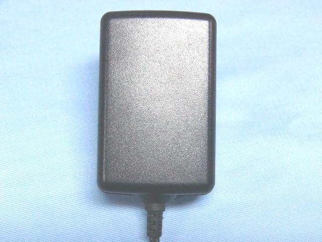
Click to zoom
Application Details
- Equipment Class
- DTS - Digital Transmission System
- Date of Grant
- Dec 22, 2009
- Application Purpose
- Original Equipment
- Date of Application
- Dec 21, 2009
- Equipment Note
- WIRELESS G ADSL2+ ROUTER
- Frequency Range
- 2412.00000000 - 2462.00000000
- Company
- D-Link Corporation
- Country
- United States
Documents & Files
Document Text
Text extracted from the exhibit documents filed with the FCC. Open a document above to read the original.
Users Manual
DSL-2600U User Manual FCC Information This equipment complies with CFR 47, Part 15.19 of the FCC rules. Operation of the equipment is subject to the following conditions: (1) this device may not cause harmful interference, and (2) this device must accept any interference received; including interference that may cause undesired operation. This device must not be co-located or operating in conjunction with any other antenna or transmitter NOTE: THE MANUFACTURER IS NOT RESPONSIBLE FOR ANY RADIO OR TV INTERFERENCE CAUSED BY UNAUTHORIZED MODIFICATIONS TO THIS EQUIPMENT. SUCH MODIFICATIONS COULD VOID THE USER’S AUTHORITY TO OPERATE THE EQUIPMENT. Federal Communications Commission (FCC) Requirements, Part 15 This equipment has been tested and found to comply with the limits for a class B digital device, pursuant to part 15 of the FCC Rules. These limits are designed to provide reasonable protection against harmful interference in a residential installation. This equipment generates, uses and can radiate radio frequency energy and, if not installed and used in accordance with the instructions, may cause harmful interference to radio communications. However, there is no guarantee that interference will not occur in a particular installation. If this equipment does cause harmful interference to radio or television reception, which can be determined by turning the equipment off and on, the user is encouraged to try to correct the interference by one or more of the following measures: ---Reorient or relocate the receiving antenna. ---Increase the separation between the equipment and receiver. ---Connect the equipment into an outlet on a circuit different from that to which the receiver is connected. ---Consult the dealer or an experienced radio/TV technician for help. Regulatory information / Disclaimers Installation and use of this Wireless LAN device must be in strict accordance with the instructions included in the user documentation provided with the product. Any changes or modifications (including the antennas) made to this device that are not expressly approved by the manufacturer may void the user’s authority to operate the equipment. The manufacturer is not responsible for any radio or television interference caused by unauthorized modification of this device, or the substitution of the connecting cables and equipment other than manufacturer specified. It is the responsibility of the user to correct any interference caused by such unauthorized modification, substitution or attachment. Manufacturer and its authorized resellers or distributors will assume no liability for any damage or violation of government CAUTION: To maintain compliance with FCC’s RF exposure guidelines, this equipment should be installed and operated with minimum distance 20cm between the radiator and your body. Use on the supplied antenna. Unauthorized antenna, modification, or attachments could damage the transmitter and may violate FCC regulations. MPE Statement (Safety Information) Your device contains a low power transmitter. When device is transmitted it sends out Radio Frequency (RF) signal. Safety Information In order to maintain compliance with the FCC RF exposure guidelines, this equipment should be installed and operated with minimum distance 20cm between the radiator and your body. Use only with supplied antenna. Unauthorized antenna, modification, or attachments could damage the transmitter and may violate FCC regulations. Table of Contents Before You Begin..........................................................................................1 Package Contents.................................................................................................1 System Requirements...........................................................................................1 Features...............................................................................................................2 HARDWARE OVERVIEW.............................................................................................3 Connections..................................................................................................3 LED Indicators..............................................................................................4 INSTALLATION............................................................................................................5 Installation Notes...................................................................................................5 Information you will need from your ADSL service provider.............................7 Information you will need about DSL-2600U...................................................8 Information you will need about your LAN or computer:..................................8 Device Installation.................................................................................................9 Power on Router...........................................................................................9 Factory Reset Button.....................................................................................9 Network Connections..................................................................................10 INTRODUCTION TO WEB CONFIGURATION.............................................................11 Preparation Before Login......................................................................................11 Logging In to the Modem.....................................................................................13 First-Time Login..........................................................................................13 Quick Setup........................................................................................................14 WAN Interface Setup...................................................................................14 LAN Interface Setup....................................................................................23 Wireless Interface …
Text truncated - open the document above for the full version.
Cover Letter(s)
CONFIDENTIALITY LETTER Date: December 21, 2009 Federal Communications Commission 7435 Oakland Mills Road Columbia, MD 21046 Gentlemen: This letter is to comply with Section 0.457(d)(2)(i) and 0.459 pertaining to confidential material. D Link Corporation would like the following documents regarding this submission for FCC ID: KA2DSL- 2600U to be kept confidential. 1. Schematic.pdf 2. Block Diagram.pdf 3. Operational Description.pdf The above material contains trade secrets or technical data, which would customarily be guarded from competitors. We do not want these documents to be accessible to the general public. Sincerely, Michael Boschma / Engineer
External Photos
EUT top view Frecom DC Power HuntKey DC power EUT bottom view Frecom DC power HuntKey DC power
ID Label/Location Info
This device complies with Part 15 of the FCC Rules. Operation is subject to the following two conditions: (1) this device may not cause harmful interference, and (2) this device must accept any interference received, including interference that may cause undesired operation. The Label must not be a stick-on paper label. The Label on these products must be permanently affixed to the product and readily visible at the time of purchase and must last the expected lifetime of the equipment not be readily detachable. Proposed Label Location on EUT EUT Bottom View/Proposed FCC ID Label Location FCC ID: KA2DSL-2600U
Internal Photos
EUT inside whole view Main & RF board component side Main & RF board solder side
Test Report
The test report consists 41 pages in total. It may be duplicated completely for legal use with the allowance of the applicant. It shall not be reproduced except in full, without the written approval of Ke Mei Ou Laboratory Corporation. The test result in the report only applied to the tested sample. FCC TEST REPORT Under FCC 15 Subpart C, Paragraph 15.247: 2008 Operating in 2400 ~ 2483.5 MHz Band Prepared For : D-Link Corporation NO.289, Sinhu 3rd., Neihu District, Taipei City 114, Taiwan, R.O.C November 25, 2009 FCC ID: KA2DSL-2600U EUT: Wireless G ADSL2 + Router Model: DSL-2600U Report Type: Original Report Test Engineer: Jacky Huang Test Date: November 9, 2009 Review By: Apollo Liu / Manager Ke Mei Ou Laboratory Co., Ltd. 7A, Jiaxiangge, Jiahuixincheng, No.3027, Shennan Rd., Futian, Shenzhen, Guangdong, P.R.China. Zip Code: 518033 Tel: + 86 755 83642690 Fax: + 86 755 83297077 www.kmolab.com D-Link Corporation FCC ID: KA2DSL-2600U KMO FCC ID Report Report #: KSZ2009110601J Page 2 of 41 TABLE OF CONTENTS 1. General Information....................................................................................................................................................3 1. 1 Notes......................................................................................................................................................................3 1. 2 Testing Laboratory..................................................................................................................................................3 1. 3 Details of Applicant................................................................................................................................................3 1. 4 Application Details..................................................................................................................................................3 1. 5 Test Item.................................................................................................................................................................3 1. 6 Test Standards.........................................................................................................................................................3 2. Technical Test...............................................................................................................................................................4 2. 1 Summary of Test Results.........................................................................................................................................4 2. 2 Antenna Requirement..............................................................................................................................................4 3. EUT Modifications.......................................................................................................................................................4 4. Conducted Power Line Test.........................................................................................................................................5 4. 1 Test Equipment.......................................................................................................................................................5 4. 2 Test Procedure........................................................................................................................................................5 4. 3 Test Setup...............................................................................................................................................................5 4. 4 Configuration of the EUT........................................................................................................................................6 4. 5 EUT Operating Condition........................................................................................................................................7 4. 6 Conducted Power Line Emission Limits..................................................................................................................7 4. 7 Conducted Power Line Test Result...........................................................................................................................8 5. FCC Part 15.247 Requirements for 802.11b/g Systems.............................................................................................12 5. 1 Test Equipment.....................................................................................................................................................12 5. 2 Test Procedure......................................................................................................................................................12 5. 3 Test Setup.............................................................................................................................................................12 5. 4 Configuration of the EUT......................................................................................................................................12 5. 5 EUT Operating Condition......................................................................................................................................12 5. 6 Limit....................................................................................................................................................................12 5. 7 Test Result............................................................................................................................................................13 6. Transmitter Spurious Radiated Emission at 3 Meters...............................................................................................28 6. 1 Test Equipment.....................................................................................................................................................28 6. 2 Test Procedure...............................................…
Text truncated - open the document above for the full version.
Test Setup Photos
Conducted emission test view Radiated emission test view
Contact Information
Applicant
Brett Adair(General Counsel)
Test Firm
SinTek Laboratory Co., Ltd.Eric Lin
Technical Specifications
| # | Rule Parts | Frequency Range | Power Output |
|---|---|---|---|
| 1 | 15C | 2.41 GHz - 2.46 GHz | 60.67 mW |
Other Applications from D-Link Corporation

KA2CS6012A1
Jul 07, 20262K Fixed Indoor Cloud Camera, 2K Fixed Indoor Wi-Fi Camera
Equipment Class
DTS - Digital Transmission SystemKA2AE65UA1
Mar 02, 2026Wi-Fi 7 BE6500 USB 3.0 Dongle
Equipment Class
NII - Unlicensed National Information Infrastructure TXKA2APE9560A1
Nov 17, 2025BE9500 Celling mount Access Point
Equipment Class
6ID - 15E 6 GHz Low Power Indoor Access PointKA2AX9UA1
Dec 04, 2024AX900 Wi-Fi 6 USB Adapter, Wi-Fi 6 AX900 USB 2.0 Dongle
Equipment Class
DSS - Part 15 Spread Spectrum TransmitterKA2AC13UA1
Dec 04, 2024AC1300 Wi-Fi 5 USB Adapter, Wi-Fi 5 AC1300 USB 2.0 Dongle
Equipment Class
DTS - Digital Transmission System