KA2DSL2640RWireless ADSL2+ Router
D-Link Corporation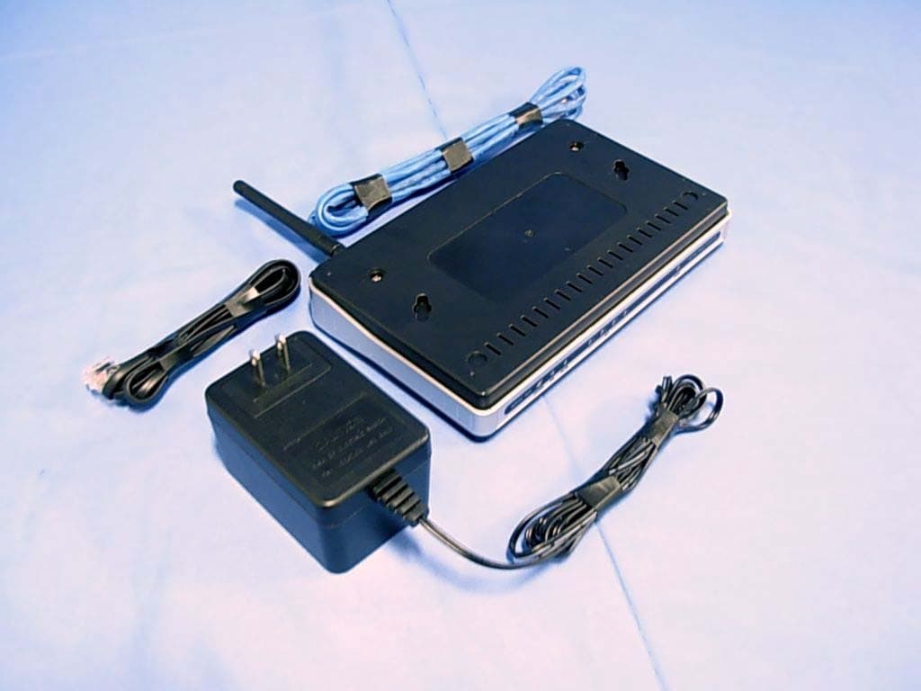
Click to zoom
Application Details
- Equipment Class
- DTS - Digital Transmission System
- Date of Grant
- Nov 24, 2007
- Application Purpose
- Original Equipment
- Date of Application
- Nov 22, 2007
- Equipment Note
- Wireless ADSL2+ Router
- Frequency Range
- 2412.00000000 - 2462.00000000
- Company
- D-Link Corporation
- Country
- United States
Documents & Files
Document Text
Text extracted from the exhibit documents filed with the FCC. Open a document above to read the original.
Users Manual
FCC Notices This device complies with Part 15 of the FCC Rules. Operation is subject to the following two conditions: (1) this device may not cause harmful interference, and (2) this device must accept any interference received, including interference that may cause undesired operation. CAUTION: Change or modification not expressly approved by the party responsible for compliance could void the user’s authority to operate this equipment. This equipment has been tested and found to comply with the limits for a Class B digital device, pursuant to Part 15 of the FCC Rules. These limits are designed to provide reasonable protection against harmful interference in a residential installation. This equipment generates, uses and can radiate radio frequency energy and, if not installed and used in accordance with the instructions, may cause harmful interference to radio communications. However, there is no guarantee that interference will not occur in a particular installation. If this equipment does cause harmful interference to radio or television reception, which can be determined by turning the equipment off and on, the user is encouraged to try to correct the interference by one or more of the following measures: --Reorient or relocate the receiving antenna. --Increase the separation between the equipment and receiver. --Connect the equipment into an outlet on a circuit different from that to which the receiver is connected. --Consult the dealer or an experienced radio/TV technician for help. CAUTION: Any changes or modifications not expressly approved by the grantee of this device could void the user's authority to operate the equipment. RF exposure warning: The equipment complies with FCC RF exposure limits set forth for an uncontrolled environment. The equipment must not be co-located or operating in conjunction with any other antenna or transmitter. Table of Contents P ACKAGE C ONTENTS .......................................................................................... 1 S YSTEM R EQUIREMENTS ..................................................................................... 1 F EATURES .......................................................................................................... 2 LEDs............................................................................................................. 4 INSTALLATION .................................................................................................... 5 B EFORE Y OU B EGIN ............................................................................................ 5 I NSTALLATION N OTES .......................................................................................... 5 D EVICE I NSTALLATION ......................................................................................... 9 Power on Router ........................................................................................ 10 Factory Reset Button.................................................................................. 10 Network Connections ..................................................................................11 SETUP ................................................................................................................ 12 Web-based Configuration Utility................................................................. 12 C ONFIGURE THE R OUTER .................................................................................. 13 Q UICK S TART .................................................................................................... 14 I NTERFACE S ETUP ............................................................................................. 19 PPPoE/PPPoA ........................................................................................... 20 Dynamic IP Address ................................................................................... 22 Static IP Address ........................................................................................ 23 Bridge Mode ............................................................................................... 24 LAN S ETUP ...................................................................................................... 25 Use the Router for DHCP........................................................................... 26 Disable the DHCP Server........................................................................... 26 Use DHCP Relay........................................................................................ 26 W IRELESS S ETUP ............................................................................................. 27 B ASIC W IRELESS .............................................................................................. 28 WEP E NCRYPTION ............................................................................................ 29 WPA S ETTINGS ................................................................................................ 30 A DVANCED S ETUP ............................................................................................. 31 ACCESS MANAGEMENT .................................................................................. 42 MAINTENTANCE................................................................................................ 48 P ASSWORD ....................................................................................................... 48 F IRMWARE U PDATE ........................................................................................... 50 RESET/RESTART SYSTEM .............................................................................. 51 D IAGNOSTICS ................................................................................................... 52 STATUS............................................................................................................... 53 S YSTEM L OG ........................................................................…
Text truncated - open the document above for the full version.
Users Manual
Section 3 – Configuration D-Link DSL-2640R User Manual 28 Basic Wireless To disable the wireless interface : click in the Deactivated option next to Access Point: and click the SAVE button. This will immediately disable the wireless access point; it is not nec essary to restart the access point to make this change. If the wireless interface has been disabled: click in the Activated option next to Access Point: and click the SAVE button. This will immediately disable the wireless access point; it is not necessary to restart the access point to make this change. The SSID can be changed to suit your wireless network. Remember that any wireless device using the access point must have the same SSID and use the same channel. The SSID can be a continuous character string (i.e. no spaces) of up to 16 characters in length. The Channel ID: may be changed to channels that are available in your region. Channels available for wireless LAN communication are subject to regional and national regulation. Click the SAVE button to save any change to the Channel. Wireless Security The wireless security features are used to limit access to the device or to encrypt data and shared information. The available standardized security for wireless LAN includes WEP and WPA Wireless security is configured with the Wireless Settings menu located in the Home directory. In the Wireless Settings menu, select the type of security you want to configure. The menu will change to present the settings specific to the method being configured. The Router’s wireless security options include three levels of WEP encryption and WPA with a user configured Pre Shared Key (PSK). Configure the wireless security arrangement to suit your 802.11g environment and click the SAVE button. The settings will go into effect immediately. There is no need to restart the access point. The table below provides a summary of the settings in the Wireless Settings menu. Note: Before enabling any security function for wireless operation, you may want to test the Router’s access point first to verify that wireless workstations can associate with it and use it for Internet access. Section 3 – Configuration D-Link DSL-2640R User Manual 29 WEP Encryption WEP (Wireless Encryption Protocol or Wired Equivalent Privacy) encryption can be enabled for security and privacy. WEP encrypts the data portion of each frame transmitted from the wireless adapter using one of the predefined keys. Decryption of the data contained in each packet can only be done if the both the receiver and transmitter have the correct key. By default authentication is disabled on the access point. To enable WEP , select the WEP-64Bits or WEP-128Bits option, configure the WEP Encryption Keys as desired and click the SAVE button. The encryption key setup is described below. Encryption Keys WEP Keys may be configured using Hex or ASCII characters. There are two levels of encryption available, each level requires a different number of characters. Select Hex or ASCII from the Key Type drop-down menu. Hex or Hexadecimal digits are defined as the numerical digits 0 – 9 and the letters A – F (upper and lower case are recognized as the same digit). ASCII characters include numbers and letters but no spaces. An upper case ASCII character is NOT recognized as the same lower case character, and therefore must be configured exactly as typed for all wireless nodes using the access point. The length of the key depends on the level of encryption used. Select the Key Length from the drop-down menu. The available key lengths are 64 or 128-bit encryption. In the spaces provided, type in Key 1 , Key 2 , Key 3 and Key 4 . The length of the character string used of the keys depends on the level (Key Length) of encryption selected. Only one key can be active. The active key is selected by clicking the radio button for the key you want to use. Click the SAVE button when you have configured WEP as desired to put the changes into effect. Section 3 – Configuration D-Link DSL-2640R User Manual 30 WPA Settings WPA uses an encryption method combined with an authentication procedure that requires an a cceptance of a pre-configured password. WPA or Wireless Protection Access is an improved standard of wireless security. The ROUTER also supports two common encryption types TKIP and AES. To configure WPA settings, select the Authentication Type option WPA-PSK to use TKIP encryption or select WPA2-PSK to use AES encryption. The encryption algorithm TKIP (Temporal Key Integrity Protocol) uses per packet key generation (based on WEP), while AES (Advanced Encryption Standard) is a block- based encryption method. Both methods require entry of a pre-shared key to allow association. Type a password from 8 to 64 characters long in the Pre-Shared Key field. Wireless MAC Address Filter MAC address device filtering on the wireless LAN can be activated and configured to allow exclusive association or deny association with the access point. To use MAC address filterin g, click to select the Activated option and specify the MAC addresses allowed or denied association in the entry fields provided. Up to 8 MAC addresses can be added to the list. Select the action to be performed on the MAC addresses in the list. Choose Allow Association to allow association to only the MAC address listed. This option will filter or deny association to any device not listed. Alternatively the Deny Association option will deny association to only the MAC addresses listed. Click SAVE to apply and save the new filtering rules. MAC address filtering can be Deactivated at any time, the MAC addresses in the list remain until they are deleted by the administrator. A MAC address on the list can be removed by highlighting it with cursor, pressing the Delete key on your keyboard and pressing SAVE . Section 3 – Configuration D-Link DSL-2640R User Manual 31 Advanced Setup The Advanced Setup folder contains windows for Routing, NAT and ADSL. Firewall This menu allows the …
Text truncated - open the document above for the full version.
Cover Letter(s)
Federal Communications Commission Authorization and Evaluation Divisio n Confidentiality Request regarding application for certification of FCC ID : KA2DSL2640R Pursuant to Sections 0.457 and 0 .459 of the Commission's Rules, we hereby request confidentia l treatment of information accompanying this application as outlined below : Exhibit Type File Name Block Diagram (DSL-2640R)BlkDia Schematics (DSL-2640R)Sche m The above materials contain trade secrets and proprietary information not customarily released t o the public . The public disclosure of these materials may be harmful to the applicant and provid e unjustified benefits to its competitors. The applicant understands that pursuant to Section 0 .457 of the Rules, disclosure of this application and all accompanying documentation will not be made before the date of the Gran t for this application. Sincerely, Jerry / Project Manager D-Link C . .ration Tel: 886-2-.600-0123 ext.5716 Fax :886-2-5550-. 9988 E-mail: [email protected] w
Cover Letter(s)
Declaration of Authorizatio n We Name: D-Link Corporation Address: No.289, Sinhu 3rd Rd, Neihu District , City: Taipei 114, Country: Taiwan, R.O . C Declare that: Name: QuieTek Corporation Address: 2F, No . 345, Xinhu 2nd Rd., Neihu District , City: Taipei City 114 , Country Taiwan, R.O .C . is authorized to apply for Certification of the following product(s) : Product description: Wireless ADSL2+ Route r Type designation : DSL-2640R Trademark : D-Link FCC ID: KA2DSL2640R on our behalf. Date: 2007/10/25 City: Taipei Name: Jerry Chiu Signature:
Cover Letter(s)
American Telecommunications Certification Body Inc. 6731 Whittier Ave, McLean, VA 22101 November 8, 2007 RE: D-Link Corporation FCC ID: KA2DSL2640R I have a few comments on this Application. Depending on your responses, kindly understand there may be additional comments. 1.) Form 731, the Agent Authorization, and the Confidentiality Request letters are signed by Jerry Chiuan at D-Lin’s office in Neihu, Taipei, Taiwan. However, the contact window associated with Grantee code KA2 is Michael Boschma with D-Link in Fountain Valley, California. There is no legal basis for Jerry Chiuan to act on behalf of D-Link. Further processing of this Application is in jeopardy until such time as this issue is resolved. 2.) The 731 form shows the upper frequency range for this device is 2472 MHz. And the Manual on page 29 indicates that the end user or technician is able to select the final country or region for selecting channels/power during the wireless setup. This is illegal, and contrary to your software attestation document signed by Jerry Chiuan. The issue of operation on non-USA frequencies must be resolved before further processing can proceed. 3.) This device is manufactured in China, but the FCC DofC logo appears on this device. You are reminded that testing of this device for Part 15B unintentional emissions for the purposes of creating a DofC report is contrary to the Rules. Where was this device tested for Part 15B? 4.) Please provide a table of RF power vs. data rate for 1, 2, 5.5, and 11MB/sec in 802.11b mode, and 6, 9, 12, 18, 24, 36, 48, and 54MB/sec in OFDM 802.11g mode. Please be sure to provide low, mid, and high channel data at the highest power data rate. 5.) Your plots in Section 2.6 of the Test Report are far too small to be useable. Please provide larger plots. Have pity on my eyes. William H. Graff President mailto: [email protected] The items indicated above must be submitted before processing can continue on the above referenced application. Failure to provide the requested information may result in application termination. Correspondence should be considered part of the permanent submission and may be viewed from the Internet after a Grant of Equipment Authorization is issued. Please do not respond to this correspondence using the email reply button. In order for your response to be processed expeditiously, you must submit your documents through the AmericanTCB.com website. Also, please note that partial responses increase processing time and should not be submitted. Any questions about the content of this correspondence should be directed to the sender.
Cover Letter(s)
Sent: Tuesday, November 20, 2007 2:57 PM Subject: RE: www.AmericanTCB.com | KA2DSL2640R | | | KA2DSL2640R_ATCB Dear Bill, Sorry for the delayed response. Concerning your previous comments, we have corrected the documents and uploaded them on ATCB website. Here's the responses: 1) Form 731, the Agent Authorization, and the Confidentiality Request letters are signed by Jerry Chiuan at D-Lin's office in Neihu, Taipei, Taiwan. However, the contact window associated with Grantee code KA2 is Michael Boschma with D-Link in Fountain Valley, California. There is no legal basis for Jerry Chiuan to act on behalf of D-Link. Further processing of this Application is in jeopardy until such time as this issue is resolved. Ans: Pls check file "ATTESTATION","Confidentiality letter" and "Declaration of Authorization".Customer adds their formal company's stamps on them. 2) The 731 form shows the upper frequency range for this device is 2472 MHz. And the Manual on page 29 indicates that the end user or technician is able to select the final country or region for selecting channels/power during the wireless setup. This is illegal, and contrary to your software attestation document signed by Jerry Chiuan. The issue of operation on non-USA frequencies must be resolved before further processing can proceed. Ans: Pls check file” (DSL-2640R)UserMan-1” ”(DSL-2640R)UserMan-2”. 3) This device is manufactured in China, but the FCC DofC logo appears on this device. You are reminded that testing of this device for Part 15B unintentional emissions for the purposes of creating a DofC report is contrary to the Rules. Where was this device tested for Part 15B? Ans: Part 15B-DoC was issued by Quietek, and the report NO. is 079220R-RFUSP01V02. 4)Please provide a table of RF power vs. data rate for 1, 2, 5.5, and 11MB/sec in 802.11b mode, and 6, 9, 12, 18, 24, 36, 48, and 54MB/sec in OFDM 802.11g mode. Please be sure to provide low, mid, and high channel data at the highest power data rate. Ans:Pls check revised test report on page 6 of 75. 5)Your plots in Section 2.6 of the Test Report are far too small to be useable. Please provide larger plots. Have pity on my eyes. Ans:Pls check revised test report on page13 of 75 & page 14 of 75. Thanks and best regards, Emily
External Photos
Report No: 079220R-RFUSP05V01 Page: 71 of 75 Version:1.0 Attachement ¾ EUT Photograph (1) EUT Photo (2) EUT Photo
ID Label/Location Info
D-Link Corporation No. 289 , Sinhu 3rd Rd , Neihu District , Taipei City 114 ,Taiwan , R.O.C. The Canada ID and DoC Label will be placed on the equipment as shown in the photograph below. Wireless ADSL2+ Router Model No.: DSL-2640R F F C C C C I I D D : : K K A A 2 2 D D S S L L 2 2 6 6 4 4 0 0 R R " This device complies with Part 15 of the FCC Rules. Operation is subject to the following two conditions: (1) this device may not cause harmful interference, and (2) this device must accept any interference may cause undesired operation. "
Internal Photos
Report No: 079220R-RFUSP05V01 Page: 72 of 75 Version:1.0 (3) EUT Photo (4) EUT Photo Report No: 079220R-RFUSP05V01 Page: 73 of 75 Version:1.0 (5) EUT Photo (6) EUT Photo Report No: 079220R-RFUSP05V01 Page: 74 of 75 Version:1.0 (7) EUT Photo Report No: 079220R-RFUSP05V01 Page: 75 of 75 Version:1.0 (8) EUT Photo
Operational Description
Report No: 079220R-RFUSP05V01 Page: 6 of 75 Version:1.0 1.2. Operational Description The EUT is capable of transferring data with a maximum wireless signal rate of up to 11 Mbps and 54Mbps in the 2.4GHz frequency — the same wireless frequency as 802.11b. The EUT also offers four Ethernet ports to support multiple computers. The advanced wireless technology built into the EUT offers data transfer speeds with a maximum wireless signal rate of up to 11 Mbps and 54Mbps through its wireless channels allowing streaming videos and other high bandwidth applications, such as online gaming events, to operate without the hassle of Ethernet cables. The ability to use high bandwidth applications also makes streaming real-time programs more enjoyable and more efficient. The device delivers Internet sharing, local area network connectivity and security in a single device. The EUT has a 10/100 WAN port for connection to Cable or xDSL modem. The four-port 10/100 Ethernet switch along with the built-in 802.11b/g wireless access point provides network connectivity to multiple machines in the Local Area Network (LAN).
RF Exposure Info
Report No. 079220R-RF-US-Exp Page: 1 of 3 Version:1.0 RF Exposure Evaluation declaration Product Name :Wireless ADSL2+ Router Model No. :DSL-2640R FCC ID. :KA2DSL2640R Applicant : D-Link Corporation Address : No.289, Sinhu 3rd Rd., Neihu Distrct, Taipei City 114, Taiwan, R.O.C. Date of Receipt : 2007/09/17 Date of Declaration : 2007/10/19 Report No. : 079220R-RF-US-Exp The declaration results relate only to the samples calculated. The declaration shall not be reproduced except in full without the written approval of QuieTek Corporation. Report No. 079220R-RF-US-Exp Page: 2 of 3 Version:1.0 1. RF Exposure Evaluation 1.1. Limits According to FCC 1.1310: The criteria listed in the following table shall be used to evaluate the environment impact of human exposure to radio frequency (RF) radiation as specified in 1.1307(b) LIMITS FOR MAXIMUM PERMISSIBLE EXPOSURE (MPE) Frequency Range (MHz) Electric Field Strength (V/m) Magnetic Field Strength (A/m) Power Density (mW/cm 2 ) Average Time (Minutes) (A) Limits for Occupational/ Control Exposures 300-1500 -- -- F/300 6 1500-100,000 -- -- 5 6 (B) Limits for General Population/ Uncontrolled Exposures 300-1500 -- -- F/1500 6 1500-100,000 -- -- 1 30 F= Frequency in MHz Friis Formula Friis transmission formula: Pd = (Pout*G)/(4*pi*r 2 ) Where Pd = power density in mW/cm 2 Pout = output power to antenna in mW G = gain of antenna in linear scale Pi = 3.1416 R = distance between observation point and center of the radiator in cm Pd id the limit of MPE, 1 mW/cm 2 . If we know the maximum gain of the antenna and the total power input to the antenna, through the calculation, we will know the distance r where the MPE limit is reached. 1.2. Test Procedure Software provided by client enabled the EUT to transmit and receive data at lowest, middle and highest channel individually. The temperature and related humidity: 18°Cand 78% RH. Report No. 079220R-RF-US-Exp Page: 3 of 3 Version:1.0 1.3. Test Result of RF Exposure Evaluation Product Wireless ADSL2+ Router Test Mode Mode 1: Transmit Test Condition RF Exposure Evaluation Antenna Gain Antenna Gain: The maximum Gain measured in fully anechoic chamber is 2dBi or 1.58 in linear scale. Output Power into Antenna & RF Exposure Evaluation Distance: IEEE 802.11b Bluetooth Function Channel Channel Frequency (MHz) Output Power to Antenna (mW) Power Density at R = 20 cm (mW/cm 2 ) 1 2412.00 112.7197 0.0355 6 2437.00 135.8313 0.0428 11 2462.00 167.8804 0.0529 IEEE 802.11g Bluetooth Function Channel Channel Frequency (MHz) Output Power to Antenna (mW) Power Density at R = 20 cm (mW/cm 2 ) 1 2412.00 69.6627 0.0220 6 2437.00 82.6038 0.0260 11 2462.00 107.3989 0.0339 The power density Pd (4th column) at a distance of 20 cm calculated from the Friis transmission formula is far below the limit of 1 mW/cm 2 .
Test Report
Report No 079220R-RFUSP05V01 Page: 1 of 75 Version:1.0 Test Report Product Name Wireless ADSL2+ Router Model No. DSL-2640R FCC ID. KA2DSL2640R Applicant D-Link Corporation Address No.289, Sinhu 3rd Rd., Neihu Distrct, Taipei City 114, Taiwan, R.O.C. Date of Receipt 2007/09/17 Issued Date 2007/10/19 Report No. 079220R-RFUSP05V01 The test results relate only to the samples tested. The test report shall not be reproduced except in full without the written approval of QuieTek Corporation. Report No 079220R-RFUSP05V01 Page: 2 of 75 Version:1.0 Test Report Certification Issued Date : 2007/10/19 Report No. : 079220R-RFUSP05V01 Product Name Wireless ADSL2+ Router Applicant D-Link Corporation Address No.289, Sinhu 3rd Rd., Neihu Distrct, Taipei City 114, Taiwan, R.O.C. Manufacturer Alpha Networks Inc. Model No. DSL-2640R FCC ID. KA2DSL2640R Rated Voltage : AC 120 V / 60 Hz EUT Voltage : AC 120 V / 60 Hz Trade Name D-Link Applicable Standard FCC CFR Title 47 Part 15 Subpart C Section 15.247: 2006 Test Result Complied The test results relate only to the samples tested. The test report shall not be reproduced except in full without the written approval of QuieTek Corporation. Documented By : ( Demi Chang / Engineering Adm. Specialist ) Reviewed By : ( Halu Chung / Assistant Engineer ) Approved By ( Roy Wang / Manager ) Report No 079220R-RFUSP05V01 Page: 3 of 75 Version:1.0 TABLE OF CONTENTS Description Page 1. General Information........................................................................................................5 1.1. EUT Description................................................................................................................5 1.2. Operational Description....................................................................................................6 1.3. Test Mode..........................................................................................................................7 1.4. Tested System Details......................................................................................................8 1.5. Configuration of tested System........................................................................................9 1.6. EUT Exercise Software...................................................................................................10 1.7. Test Facility......................................................................................................................11 2. Peak Power Output.......................................................................................................12 2.1. Test Equipment...............................................................................................................12 2.2. Test Setup.......................................................................................................................12 2.3. Limits...............................................................................................................................12 2.4. Test Specification............................................................................................................12 2.5. Uncertainty......................................................................................................................12 2.6. Test Result......................................................................................................................13 3. Conducted Emission....................................................................................................15 3.1. Test Equipment...............................................................................................................15 3.2. Test Setup.......................................................................................................................15 3.3. Limits...............................................................................................................................16 3.4. Test Procedure................................................................................................................16 3.5. Test Specification............................................................................................................16 3.6. Uncertainty......................................................................................................................16 3.7. Test Result......................................................................................................................17 3.8. Test Photo.......................................................................................................................25 4. Radiated Emission........................................................................................................26 4.1. Test Equipment...............................................................................................................26 4.2. Test Setup.......................................................................................................................26 4.3. Limits...............................................................................................................................27 4.4. Test Procedure................................................................................................................27 4.5. Test Specification............................................................................................................27 4.6. Uncertainty......................................................................................................................27 4.7. Test Result......................................................................................................................28 4.8. Test Photo.......................................................................................................................44 5. Band Edge.....................................................................................................................46 5.1. Test Equipment..…
Text truncated - open the document above for the full version.
Test Report
Report No 079220R-RFUSP05V01 Page: 32 of 75 Version:1.0 Harmonic & Spurious: Site : Site 1 Time : 2007/09/26 - 13:25 Limit : FCC_SpartC_15.247_H_03M_PK Margin : 6 EUT : Wireless ADSL2+ ROUTER Probe : FCC_CB4_1-18G(2007-9) - HORIZONTAL Power : AC 120V/ 60Hz Note : Mode 1: Transmit-B-CH1 Frequency (MHz) Correct Factor (dB) Reading Level (dBuV) Measure Level (dBuV/m) Margin (dB) Peak Limit (dBuV/m) Average Limit (dBuV/m) Detector Type 1 4824.300 -0.060 39.320 39.259 -34.741 74.000 54.00 PEAK 2 7236.500 2.841 39.680 42.521 -31.479 74.000 54.00 PEAK 3 9648.320 8.751 38.990 47.741 -26.259 74.000 54.00 PEAK 4 * 12060.620 15.822 36.890 52.712 -21.288 74.000 54.00 PEA…
Text truncated - open the document above for the full version.
Contact Information
Applicant
Brett Adair(General Counsel)
Technical Contact
QuieTek CorporationEmily Chen
[email protected]+886 2 8792 6808
2F, No. 345, Xinhu 2nd Rd · Taipei · Taiwan
Test Firm
DEKRA Testing and Certification Co., Ltd.Sky Hsu
Technical Specifications
| # | Rule Parts | Frequency Range | Power Output |
|---|---|---|---|
| 1 | 15C | 2.41 GHz - 2.46 GHz | 168.00 mW |
Other Applications from D-Link Corporation

KA2CS6012A1
Jul 07, 20262K Fixed Indoor Cloud Camera, 2K Fixed Indoor Wi-Fi Camera
Equipment Class
DTS - Digital Transmission SystemKA2AE65UA1
Mar 02, 2026Wi-Fi 7 BE6500 USB 3.0 Dongle
Equipment Class
NII - Unlicensed National Information Infrastructure TXKA2APE9560A1
Nov 17, 2025BE9500 Celling mount Access Point
Equipment Class
6ID - 15E 6 GHz Low Power Indoor Access PointKA2AX9UA1
Dec 04, 2024AX900 Wi-Fi 6 USB Adapter, Wi-Fi 6 AX900 USB 2.0 Dongle
Equipment Class
DSS - Part 15 Spread Spectrum TransmitterKA2AC13UA1
Dec 04, 2024AC1300 Wi-Fi 5 USB Adapter, Wi-Fi 5 AC1300 USB 2.0 Dongle
Equipment Class
DTS - Digital Transmission System