KA2DWLAG530A4IEEE 802.11a/g Wireless PCI Adapter
D-Link Corporation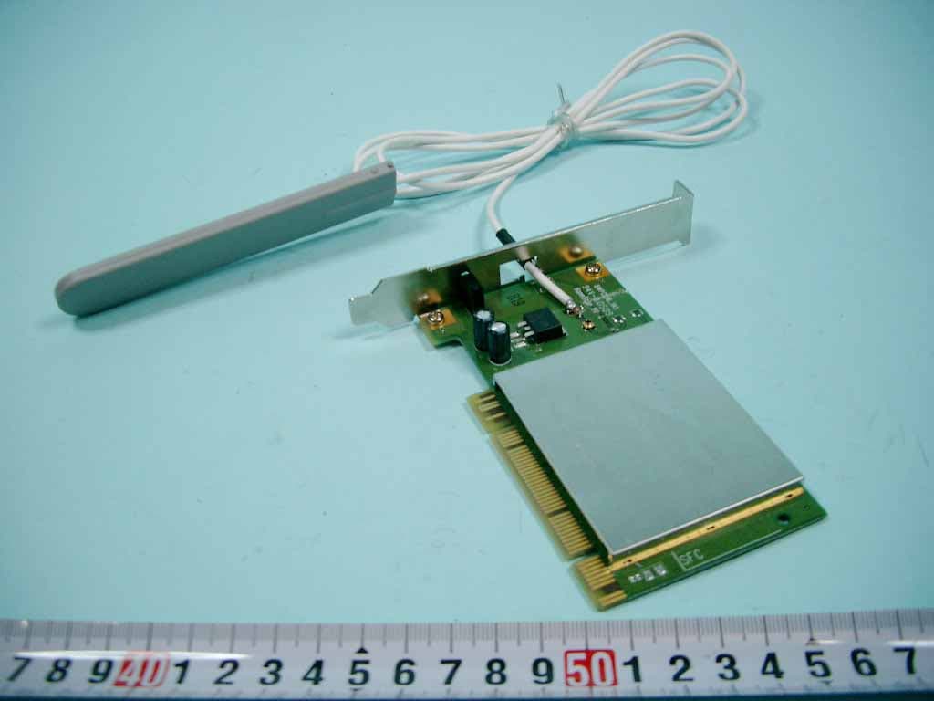
Click to zoom
Application Details
- Equipment Class
- NII - Unlicensed National Information Infrastructure TX
- Date of Grant
- Jul 07, 2005
- Application Purpose
- Original Equipment
- Date of Application
- Jul 07, 2005
- Equipment Note
- IEEE 802.11a/g Wireless PCI Adapter
- Frequency Range
- 5250.00000000 - 5350.00000000
- Company
- D-Link Corporation
- Country
- United States
Documents & Files
Document Text
Text extracted from the exhibit documents filed with the FCC. Open a document above to read the original.
Users Manual
Manual Building Networks for People 11a/11g Dualband (2.4GHz/5GHz) DWL-AG530 D-Link AirPremier AG TM Wireless 108Mbps PCI Adapter 2 Contents Package Contents................................................................................. 3 Introduction............................................................................................ 4 Features............................................................................................... 5 Wireless Basics .................................................................................... 6 Getting Started.................................................................................... 10 Using the Configuration Utility.............................................................. 13 Networking Basics.............................................................................. 22 Troubleshooting................................................................................... 35 Technical Specifications...................................................................... 40 Contacting Technical Support.............................................................. 42 Warranty and Registration.................................................................... 43 Appendix............................................................................................ 46 How to Replace the Bracket EAP Types Definitions of Configuration Terms 3 Package Contents Contents of Package: D-Link AirPremier AG TM DWL-AG530 11a/11g Dualband (2.4GHz/5GHz) Wireless 108Mbps PCI Adapter Manual, Warranty and Drivers on CD Printed Quick Installation Guide Low Prefile Bracket If any of the above items are missing, please contact your reseller. System Requirements for Configuration: An 802.11a, 802.11b or 802.11g access point (for Infrastruc- ture mode) or another 802.11a, 802.11b, or 802.11g wireless adapter (for Ad-Hoc; Peer-to-Peer networking mode). At least 128MB of memory and a 500MHz processor Windows XP/2000 A desktop computer with an available 32-bit PCI 2.2 slot * Due to DFS (Dynamic Frequency Selection), 802.11a SSID broadcast (Ad-Hoc mode) is always disabled. 4 Introduction *Not all servers can provide Authentication The DWL-AG530 has the newest, strongest and most advanced security features available today. When used with other 802.11 WPA/WPA2 (Wi-Fi Protected Access/Wi-Fi Protected Access 2 TM ) and 802.1X compatible products in a network with a RADIUS server, the security features include: WPA/WPA2: Wi-Fi Protected Access/Wi-Fi Protected Access 2 TM which authorizes and identifies users based on a secret key that changes automatically at regular intervals. WPA/WPA2 uses TKIP (Temporal Key Integrity Protocol) to change the temporal key every 10,000 packets (a packet is a kind of message transmitted over a network.) This ensures much greater security than the standard WEP security. (By contrast, the previous WEP encryption implementations required the keys to be changed manually.) 802.1X: Authentication which is a first line of defense against intrusion. In the authentication process, the Authentication Server* verifies the identity of the client attempting to connect to the network. Unfamiliar clients would be denied access. For home users that will not incorporate a RADIUS server in their network, the security for the DWL-AG530, used in conjunction with other WPA/WPA2- compatible 802.11 products, will still be much stronger than ever before. Utilizing the Pre- Shared Key mode of WPA/WPA2, the DWL-AG530 will obtain a new security key every time it connects to the 802.11 network. You only need to input your encryption information once in the configuration menu. No longer will you have to manually input a new WEP key frequently to ensure security. With the DWL-AG530, you will automatically receive a new key every time you connect, vastly increasing the safety of your communication. At up to fifteen times the speed of previous wireless devices (up to 108Mbps in Super AG mode), you can work faster and more efficiently, increasing productivity. With the DWL-AG530, bandwidth-intensive applications like graphics or multimedia will benefit significantly because large files are able to move across the network quickly. Inclusion of all three standards (802.11g; 802.11a; 802.11b) means that the DWL-AG530 is versatile enough to allow connection to almost any 802.11 network or device. 5 Features Versatility - The DWL-AG530 is fully compatible with IEEE 802.11a and 802.11b standards, making it interoperable with 802.11a and 802.11b wire- less routers and access points in your office, home or at public wireless hotspots. 32-bit PCI Performance/Plug & Play Connectivity -The DWL-AG530 is a powerful 32-bit PCI adapter that installs quickly and easily into desk- top PCs, and when used with other D-Link Air Premier AG TM products will automatically connect to the network out of the box. Compatible with 802.11a, 802.11b and 802.11g Devices - Fully compat- ible with the IEEE 802.11a, 802.11b and 802.11g standards, the DWL-AG530 can connect with existing 802.11b, 802.11g- or 802.11a- compliant routers, access points and cards. That means you can still communicate with col- leagues and friends while you have the ability to link to even more wireless Better Security with 802.1X and WPA/WPA2 -With the DWL-AG530 in your desktop PC you can securely connect to a wireless network using 802.1x for wireless authentication, as well as WPA/WPA2 (Wi-Fi Protected Access/Wi-Fi Protected Access 2 TM ) providing you a much higher level of security for your data and communication than has previously been avail- able. Faster Wireless Networking with speeds up to 108Mbps in Turbo mode - Faster data transfers mean increased productivity. With the DWL- AG530 in your PC, you will have the flexibility of wireless networking speeds that save you time and money. * IEEE 802.11a standard to provide wireless 54Mbps data rate, and up to 108Mbps (only for USA and…
Text truncated - open the document above for the full version.
External Photos
SPORTON International Inc. PAGE NUMBER : A1 OF A11 TEL : 886-2-2696-2468 ISSUED DATE : Jun,20,2005 FAX : 886-2-2696-2255 APPENDIX A. Photographs of EUT SPORTON International Inc. PAGE NUMBER : A11 OF A11 TEL : 886-2-2696-2468 ISSUED DATE : Jun,20,2005 FAX : 886-2-2696-2255
ID Label/Location Info
Label Location
Internal Photos
SPORTON International Inc. PAGE NUMBER : A3 OF A11 TEL : 886-2-2696-2468 ISSUED DATE : Jun,20,2005 FAX : 886-2-2696-2255 SPORTON International Inc. PAGE NUMBER : A4 OF A11 TEL : 886-2-2696-2468 ISSUED DATE : Jun,20,2005 FAX : 886-2-2696-2255 SPORTON International Inc. PAGE NUMBER : A5 OF A11 TEL : 886-2-2696-2468 ISSUED DATE : Jun,20,2005 FAX : 886-2-2696-2255 SPORTON International Inc. PAGE NUMBER : A6 OF A11 TEL : 886-2-2696-2468 ISSUED DATE : Jun,20,2005 FAX : 886-2-2696-2255 SPORTON International Inc. PAGE NUMBER : A7 OF A11 TEL : 886-2-2696-2468 ISSUED DATE : Jun,20,2005 FAX : 886-2-2696-2255 SPORTON International Inc. PAGE NUMBER : A8 OF A11 TEL : 886-2-2696-2468 ISSUED DATE : Jun,20,2005 FAX : 886-2-2696-2255 SPORTON International Inc. PAGE NUMBER : A9 OF A11 TEL : 886-2-2696-2468 ISSUED DATE : Jun,20,2005 FAX : 886-2-2696-2255 SPORTON International Inc. PAGE NUMBER : A10 OF A11 TEL : 886-2-2696-2468 ISSUED DATE : Jun,20,2005 FAX : 886-2-2696-2255
RF Exposure Info
FCC ID: KA2DWLAG530A4 Issued on May 24, 2005 Report No.: FR542514 SPORTON International Inc. Page No. : 53 of 57 TEL : 886-2-2696-2468 Issued Date : May 24, 2005 FAX : 886-2-2696-2255 5.10. RF Exposure (Band 5150-5250MHz, 5250-5350MHz) 5.10.1. Limit For Maximum Permissible Exposure (MPE) This product can be classified as mobile device, so the 20cm separation distance warning is required. In this section, the power density at 20cm location is calculated to examine if it is lower than the limit. (A) Limits for Occupational / Controlled Exposure Frequency Range (MHz) Electric Field Strength (E) (V/m) Magnetic Field Strength (H) (A/m) Power Density (S) (mW/ cm²) Averaging Time |E|²,|H|² or S (minutes) 0.3-3.0 614 1.63 (100)* 6 3.0-30 1842 / f 4.89 / f (900 / f)* 6 30-300 61.4 0.163 1.0 6 300-1500 F/300 6 1500-100,000 5 6 (B) Limits for General Population / Uncontrolled Exposure Frequency Range (MHz) Electric Field Strength (E) (V/m) Magnetic Field Strength (H) (A/m) Power Density (S) (mW/cm²) Averaging Time |E|²,|H|² or S ( minutes ) 0.3-1.34 614 1.63 (100)* 30 1.34-30 824/f 2.19/f (180/f)* 30 30-300 27.5 0.073 0.2 30 300-1500 F/1500 30 1500-100,000 1.0 30 F = frequency in MHz *Plane-wave equivalent power density 5.10.2. MPE Calculation Method E (V/m) d GP××30 Power Density: Pd (mW/cm²) 377 2 E E Electric field (V/m) P Peak RF output power (mW) G EUT Antenna numeric gain (numeric) d Separation distance between radiator and human body (m) The formula can be changed to Pd 2 377 30 d GP × ×× From the peak EUT RF output power, the minimum mobile separation distance, d=20cm, as well as the gain of the used antenna, the RF power density can be obtained. FCC ID: KA2DWLAG530A4 Issued on May 24, 2005 Report No.: FR542514 SPORTON International Inc. Page No. : 54 of 57 TEL : 886-2-2696-2468 Issued Date : May 24, 2005 FAX : 886-2-2696-2255 5.10.3. Calculated Result and Limit Temperature: 15°C Relative Humidity: 62% Duty Cycle of the Equipment During the Test: 100.00% Test Engineer: Steven Lu Normal Mode Mode 1 Frequency Antenna Gain (dBi) Antenna Gain (numeric) Peak Output Power (dBm) Peak Output Power ( mW ) Power Density (S) (mW/cm²) Limit of Power Density (S) (mW/cm²) 5180 MHz 2.20 1.66 11.13 12.97 0.0043 1 5260 MHz 2.20 1.66 11.73 14.89 0.0049 1 5320 MHz 2.20 1.66 17.85 60.95 0.0201 1 Mode 2 Frequency Antenna Gain (dBi) Antenna Gain (numeric) Peak Output Power (dBm) Peak Output Power ( mW ) Power Density (S) (mW/cm²) Limit of Power Density (S) (mW/cm²) 5180 MHz 5.00 3.16 11.13 12.97 0.0082 1 5260 MHz 5.00 3.16 11.73 14.89 0.0094 1 5320 MHz 5.00 3.16 17.85 60.95 0.0383 1 FCC ID: KA2DWLAG530A4 Issued on May 24, 2005 Report No.: FR542514 SPORTON International Inc. Page No. : 55 of 57 TEL : 886-2-2696-2468 Issued Date : May 24, 2005 FAX : 886-2-2696-2255 Turbo Mode Mode 1 Frequency Antenna Gain (dBi) Antenna Gain (numeric) Peak Output Power (dBm) Peak Output Power ( mW ) Power Density (S) (mW/cm²) Limit of Power Density (S) (mW/cm²) 5210 MHz 2.20 1.66 11.70 14.79 0.0049 1 5250 MHz 2.20 1.66 11.82 15.21 0.0050 1 5290 MHz 2.20 1.66 14.89 30.83 0.0102 1 Mode 2 Frequency Antenna Gain (dBi) Antenna Gain (numeric) Peak Output Power (dBm) Peak Output Power ( mW ) Power Density (S) (mW/cm²) Limit of Power Density (S) (mW/cm²) 5210 MHz 5.00 3.16 11.70 14.79 0.0093 1 5250 MHz 5.00 3.16 11.82 15.21 0.0096 1 5290 MHz 5.00 3.16 14.89 30.83 0.0194 1
Test Report
FCC ID: KA2DWLAG530A4 Issued on May 24, 2005 Report No.: FR542514 SPORTON International Inc. TEL : 886-2-2696-2468 FAX : 886-2-2696-2255 FCC TEST REPORT CATEGORY : Mobile PRODUCT NAME : IEEE 802.11a/g Wireless PCI Adapter FCC ID. : KA2DWLAG530A4 FILING TYPE : Certification BRAND NAME : D-Link MODEL NAME : DWL-AG510, DWL-AG530, WPC-D16, WPC-D18 APPLICANT : D-Link Corporation No.8, Li-shing Road VII, Science-based Industrial Park,Hsinchu, Taiwan. MANUFACTURER : Same as applicant ISSUED BY : SPORTON INTERNATIONAL INC. 6F, No. 106, Sec. 1, Hsin Tai Wu Rd., His Chih, Taipei Hsien, Taiwan, R.O.C. Statements: Only the test result of 802.11a part is shown in this test report. (5150MHz ~ 5250MHz & 5250MHz ~ 5350MHz) The test result in this report refers exclusively to the presented test model / sample. Without written approval of SPORTON International Inc., the test report shall not be reproduced except in full. Certificate or Test Report could not be used by the applicant to claim the product endorsement by CNLA, NVLAP or any agency of U.S. government. The test equipment used to perform the test are calibrated and traceable to NML/ROC or NIST/USA. 1190 ILAC MRA FCC ID: KA2DWLAG530A4 Issued on May 24, 2005 Report No.: FR542514 SPORTON International Inc. Page No. : i TEL : 886-2-2696-2468 Issued Date: May 24, 2005 FAX : 886-2-2696-2255: Table of Contents History of this test report....................................................................................................................................ii CERTIFICATE OF COMPLIANCE.......................................................................................................................iii 1. General Description of Equipment under Test.............................................................................................1 1.1. Applicant ......................................................................................................................................................................................... 1 1.2. Manufacturer ................................................................................................................................................................................... 1 1.3. Basic Description of Equipment under Test .................................................................................................................................... 1 1.4. Features of Equipment under Test .................................................................................................................................................. 1 1.5. Antenna Description........................................................................................................................................................................ 2 1.6. Table for Carrier Frequencies ......................................................................................................................................................... 2 1.7. Table for Maximum Conducted Output Power ................................................................................................................................ 2 2. Test Configuration of the Equipment under Test.........................................................................................3 2.1. Connection Diagram of Test System............................................................................................................................................... 3 2.2. The Test Mode Description ............................................................................................................................................................. 3 2.3. Description of Test Supporting Units ............................................................................................................................................... 4 3. General Information of Test............................................................................................................................5 3.1. Test Facility ..................................................................................................................................................................................... 5 3.2. Test Conditions ............................................................................................................................................................................... 5 3.3. Standards for Methods of Measurement ......................................................................................................................................... 5 3.4. Frequency Range Investigated ....................................................................................................................................................... 5 3.5. Test Distance................................................................................................................................................................................... 5 3.6. Test Software .................................................................................................................................................................................. 5 4. List of Measurements......................................................................................................................................7 4.1. Summary of the Test Results .......................................................................................................................................................... 7 5. Test Result .......................................................................................................................................................8 5.1. Test of 26dB Spectrum Bandwidth .................................................................................................................................................. 8 5.2. Test of Maximum Conducted Output Power .....................................................................…
Text truncated - open the document above for the full version.
Contact Information
Applicant
Brett Adair(General Counsel)
Technical Contact
Sporton International Inc.Wayne Hsu
[email protected]886-3-327-3456
No. 52, Hwa Ya 1st Rd., Kwei-Shan Hsiang, · TaoYuan Hsien · Taiwan
Test Firm
Sporton International Inc.Kathy Lin
Technical Specifications
| # | Rule Parts | Frequency Range | Power Output |
|---|---|---|---|
| 2 | 15E | 5.25 GHz - 5.35 GHz | 60.95 mW |
Other Applications from D-Link Corporation

KA2CS6012A1
Jul 07, 20262K Fixed Indoor Cloud Camera, 2K Fixed Indoor Wi-Fi Camera
Equipment Class
DTS - Digital Transmission SystemKA2AE65UA1
Mar 02, 2026Wi-Fi 7 BE6500 USB 3.0 Dongle
Equipment Class
NII - Unlicensed National Information Infrastructure TXKA2APE9560A1
Nov 17, 2025BE9500 Celling mount Access Point
Equipment Class
6ID - 15E 6 GHz Low Power Indoor Access PointKA2AX9UA1
Dec 04, 2024AX900 Wi-Fi 6 USB Adapter, Wi-Fi 6 AX900 USB 2.0 Dongle
Equipment Class
DSS - Part 15 Spread Spectrum TransmitterKA2AC13UA1
Dec 04, 2024AC1300 Wi-Fi 5 USB Adapter, Wi-Fi 5 AC1300 USB 2.0 Dongle
Equipment Class
DTS - Digital Transmission System